Table of Contents
Advertisement
Quick Links
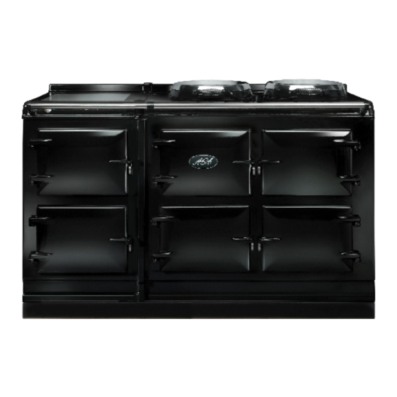
AGA TOTAL CONTROL
Model No. - TC3 & TC5
Installation
Guide
REMEMBER: when replacing a part on this appliance, use only replacement parts
that you can be assured conform to the safety and performance specification that
we require. Do not use reconditioned or copy parts that have not been clearly
authorised by AGA.
PLEASE READ THESE INSTRUCTIONS BEFORE COMMENCING SITE SURVEY
OR INSTALLING THIS APPLIANCE.
IMPORTANT :
SAVE INSTRUCTIONS FOR THE LOCAL INSPECTORS USE
CUSTOMER: KEEP THESE INSTRUCTIONS FOR FUTURE REFERENCE
3139291
For use in USA/Canada
09/13 EINS 516294
Advertisement
Table of Contents

Related Manuals for AGA Total Control ATC3


Summary of Contents for AGA Total Control ATC3
- Page 1 AGA TOTAL CONTROL Model No. - TC3 & TC5 Installation Guide REMEMBER: when replacing a part on this appliance, use only replacement parts that you can be assured conform to the safety and performance specification that we require. Do not use reconditioned or copy parts that have not been clearly authorised by AGA.
-
Page 2: Table Of Contents
GENERAL INSTALLATION REQUIREMENTS APPLIANCE DIMENSIONS - AGA TC3 APPLIANCE DIMENSIONS - AGA TC5 INSTALLATION CONNECTING TO THE POWER SUPPLY - AGA TC3 POWER SUPPLY - HOTCUPBOARD (AGA TC5) MAINS SUPPLY LOCATION - AGA TC3 MAINS SUPPLY LOCATION - AGA TC5... -
Page 3: General Notes
(740mm). A wooden template (skate with castor wheels) of dimensions 39 ” (1005mm) x ” 740mm could be used to check if the AGA Total Control fully built appliance is able to fit through the property grounds and doors into its installation position in the kitchen. It must also be considered that the height of the appliance is 37 ”... -
Page 4: Appliance Dimensions - Aga Tc3
In particular the width across the appliance recess could be critical. APPLIANCE WEIGHT Model: AGA Total Control (TC3) - 816 lbs (370 Kg) PACKAGING WEIGHT 1135 lbs (515 Kg) -
Page 5: Appliance Dimensions - Aga Tc5
10mm beyond the figures quote above. This allows safe margin to take into account the natural dimensional variations found in major castings. In particular the width across the appliance recess could be critical. APPLIANCE WEIGHT Model: AGA Total Control (TC3) - 816 lbs (370 Kg) Hotcupboard - 110kg... -
Page 6: Installation
It is essential that the base or hearth on which the range stands should be level and be capable of supporting the total weight of the range. The base of the built-in AGA plinth must be level and sit above finished floor height for service access. - Page 7 Fig. 3 DESN 516589...
-
Page 8: Connecting To The Power Supply - Aga Tc3
CONNECTION TO THE POWER SUPPLY - AGA TC3 Electric Shock Hazard Rating Plate is located behind removable plinth, see Fig. 4. Electrical Grounding is required on this appliance. DO NOT connect to the electrical supply until the appliance is permanently grounded. -
Page 9: Power Supply - Hotcupboard (Aga Tc5)
POWER SUPPLY - HOTCUPBOARD (AGA TC5) The hotcupboard attachment requires an independent single phase supply. It has a maximum load of 6 amps, protected by an appropriate branch circuit supply. 110/120V 60 Hz FLEXIBLE CORD AND PLUG PARALLEL TYPE. The appliance when installed, must be electrically grounded in accordance with local or regional codes. -
Page 10: Mains Supply Location - Aga Tc3
MAINS SUPPLY LOCATION - AGA TC3 RATING LABEL LOCATED BEHIND PLINTH, PULL TO REMOVE THE MAINS SUPPLY CONNECTION AND ISOLATION POINT MUST BE WITHIN THE ZONE SHOWN Fig. 4 DESN 516295... -
Page 11: Mains Supply Location - Aga Tc5
MAINS SUPPLY LOCATION - AGA TC5 HOTCUPBOARD POWER SUPPLY MAINS CABLE FED FROM CONTROL TRAY LEFT OR RIGHT EXIT THROUGH DUCTING DEPENDENT UPON POSITION OF SUPPLY Fig. 5 DESN 516562 SOCKET RATING LABEL LOCATED BEHIND PLINTH, PULL TO REMOVE, THE MAINS SUPPLY CONNECT POINT MUST BE WITHIN THE ZONES SHOWN Fig. -
Page 12: Hotcupboard Installation
NOTE: The AGA TC5 hotcupboard should arrive with the top plate in a jacked up position. This is to allow the complete appliance to be slid onto its plinth when alongside the AGA TC3 without the top plate clashing. The hotcupboard top plate should then be wound down to its correct height once the appliance is in its final position. - Page 13 2. Position the plinth alongside the AGA Total Control leaving no gap between the two plinths (See Fig. 8). Check with a spirit level that the plinth level is correct, and also check height differential between the hotcupboard plinth and Total Control plinth is correct ”...
- Page 14 4. Run a straight edge along the front of the AGA Total Control plinth, to ensure the front face of both plinths sit squarely against the straight edge. (See Fig. 10) When satisfied both plinths sit squarely, jacking screws can be tightened until they just make contact with the AGA Total Control plinth and locking screws can now be tightened.
- Page 15 DESN 516552 7. The hotcupboard top plate is set (5mm) higher than the AGA Total Control top plate. This is to prevent damage to the enamel during installation. Lower the top plate using the adjusters (See Figs. 13 and 14).
- Page 16 9. Slide the complete handrail assembly over the left hand and centre fixing studs. Once the assembly has been fitted to the AGA appliance, fit the handrail endcaps (ensuring the handrail is evenly spaced at each end). The endcaps should be carefully pushed into place until they sit flush with the outside face of each bracket.
-
Page 17: Handrail Connection - Aga Tc3
Fig. 15 DESN 516569 HANDRAIL CONNECTION - AGA TC3 Fig. 16 DESN 516560 Handrail brackets. endcaps and handrails require assembly. Locate endcaps onto handrail, place brackets over endcaps and then slide complete assembly onto locating studs. Once assembly is correctly located, lock into position with grub screws (located on underside... -
Page 18: Mains Cord And Wiring Diagram - Aga Tc3
MAINS CORD AND WIRING DIAGRAM - AGA TC3 Fig. 17... -
Page 19: Wiring Diagram - Aga Tc5 (Hotcupboard)
WIRING DIAGRAM - AGA TC5 (HOTCUPBOARD OPTION) COLOUR KEYS/COLLEURS CAUTION: LABEL ALL WIRES PRIOR TO BR - BROWN/MARRON DISCONNECTION, WHEN SERVICING CONTROLS BL - BLUE/BLEU WIRING ERRORS CAN CAUSE IMPROPER AND GR - GREEN/VERT DANGEROUS OPERATION. OR - ORANGE/ORANGE BK - BLACK/NOIR... -
Page 20: Instructions
INSTRUCTIONS Attach warning hanger (EGLL516660) located in literature pack, to AGA Total Control handrail when installation is complete. Advise customer to remove and read warning label. Hand this Installation Guide to the user for retention and instruct in the safe operation of the appliance. - Page 24 For further advice or information contact your local AGA Specialist With AGA’s policy of continuous product improvement, the Company reserves the right to change specifications and make modifications to the appliance described and illustrated at any time US Office: AGA MARVEL 1260 E Van Deinse St.
Need help?
Do you have a question about the Total Control ATC3 and is the answer not in the manual?
Questions and answers