Table of Contents
Advertisement
Quick Links
Advertisement
Table of Contents

Related Manuals for AGA ATC2EPWT


Summary of Contents for AGA ATC2EPWT
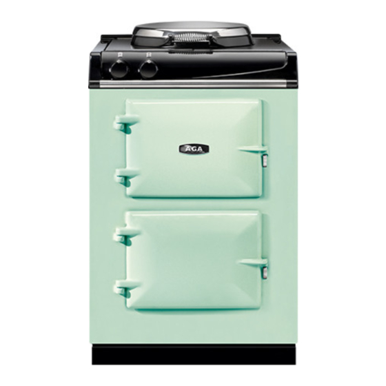
- Page 1 AGA CITY24 Installation Guide PLEASE READ THESE INSTRUCTIONS BEFORE COMMENCING SITE SURVEY OR INSTALLING THIS APPLIANCE. IMPORTANT : SAVE INSTRUCTIONS FOR FUTURE REFERENCE IMPORTANT : CONSERVER CES INSTRUCTIONS POUR REFERENCE FUTURE For use in USA/Canada 09/14 EINS 516899...
-
Page 2: Table Of Contents
CONTENTS SECTION PAGE PRODUCT SAFETY GENERAL NOTES HEALTH AND SAFETY GENERAL INSTALLATION REQUIREMENTS REMOVAL FROM PALLET AND RANGE INSTALLATION RANGE DIMENSIONS CLEARANCES CONNECTION TO THE POWER SUPPLY POWER CORD ROUTING CONTROL KNOB AND HANDRAIL CONNECTION WIRING DIAGRAM AGA CITY24 CHECKLIST... -
Page 3: Product Safety
PRODUCT SAFETY MEANING/DESCRIPTION SYMBOL SIGNIFICATION/DESCRIPTION WARNING/CAUTION AVERTISSEMENT An appropriate safety instruction Une consigne de sécurité should be followed or caution to a appropriée doivent être suivies ou potential hazard exists. garde d’un danger potentiel exists. DANGEROUS VOLTAGE TENSION DANGEREUSE To indicate hazards arising from Pour indiquer les dangers dangerous voltages. -
Page 4: General Notes
Regulations. It should be in accordance also with any relevant requirements of the Local Authority. In your own interest and that of safety to comply with the law, all appliances should be installed by an authorized AGA distributor in accordance with the relevant regulations. -
Page 5: Removal From Pallet And Range Installation
REMOVAL FROM PALLET AND RANGE INSTALLATION Removing of transit brackets - Unscrew 4 screws and NOTE: Care must be taken not to trap power cord. remove brackets, from front and two screws from rear. MAINS CABLE Range to be removed from rear of pallet only. Recess provided for suitable appliance dolly. - Page 6 REMOVAL FROM PALLET AND RANGE INSTALLATION Range can now be pushed back on its wheels into Levelling of range - Use 13mm socket to adjust wheel desired position. mechanism for FINE adjustment on both sides at rear of the appliance. NOTE: Care must be taken not to trap mains cable.
-
Page 7: Range Dimensions
1/4” (6mm) beyond the figures quoted above. This allows safe margin to take into account the natural dimensional variations found in major castings. In particular the width across the range recess could be critical. APPLIANCE WEIGHT (Excludes Packaging) Model: AGA CITY24 - 492lbs (223kg) -
Page 8: Clearances
” (116mm) clearance is required on the left hand side for oven doors access. If the AGA is to be installed in a brick recess, then the minimum clearance should be increased by at least 1/8” (6mm), to allow for the walls not being square. -
Page 9: Connection To The Power Supply
CONNECTION TO THE POWER SUPPLY Electric Shock Hazard Rating Plate is located behind removable plinth, see Fig. 4. Electrical Grounding is required on this appliance. DO NOT connect to the electrical supply until the appliance is permanently grounded. This appliance must be connected to a grounded metallic permanent supply or a grounding connector should be connected to the grounding terminal or wire lead on the appliance. -
Page 10: Power Cord Routing
MAINS CABLE ROUTING SECURE MAINS CABLE USING ‘P’ CLIPS FOR LEFT HAND OR RIGHT HAND CABLE MANAGEMENT Fig. 10 DESN 516918 POWER CORD 50A/250V 12500W RATED FITTED WITH NEMA 14-50P RIGHT ANGLED PLUG (MATCHING RECEPTACLE 14-50R) UL OR CSA APPROVED Fig. -
Page 11: Control Knob And Handrail Connection
DESN 516875 Control Knob Location Ensure control knobs are located onto spindles correctly, as shown in Fig 12. Handrail Location - AGA City24 (Traditional) Locate handrail onto spindle, lock into position with grub screws (located on the inside of the bracket). -
Page 12: Wiring Diagram
WIRING DIAGRAM Fig. 13... -
Page 13: Aga City24 Checklist
AGA CITY24 CHECKLIST SERIAL No. Tick Box Check hotplate lid and setting Check oven door seals, adjust door alignment if necessary. Slow cook oven rope seals MUST have a gap between the door hinges. The roasting oven is fitted with a continuous seal. - Page 16 For further advice or information contact your local AGA Specialist With AGA Marvel’s policy of continuous product im- provement, the Company reserves the right to change specifications and make modifications to the appliance described and illustrated at any time. Supplied by AGA Marvel 1260 E.
Need help?
Do you have a question about the ATC2EPWT and is the answer not in the manual?
Questions and answers