Table of Contents
Advertisement
Quick Links
Advertisement
Table of Contents

Related Manuals for AGA AEL48DF-SS


Summary of Contents for AGA AEL48DF-SS
- Page 1 48 Dual Fuel Owner’s Guide User & Installation Instructions U110667 - 01A...
- Page 2 WARNING! If the information in these instructions is not followed exactly, a fire or explosion may result causing property damage, personal injury or death. DO NOT store or use gasoline or other flammable vapors and liquids in the vicinity of this or any other appliance. WHAT TO DO IF YOU SMELL GAS DO NOT try to light any appliance.
-
Page 3: Table Of Contents
Contents Important Safety Information Range Overview Cooking Tips Cooking Table Cleaning Your Range Troubleshooting Service and Parts Installation Fitting the Flue, Flue Vent and Side Panels 10. Removing the Side Panels 11. Gas Connection 12. Conversion to LP Gas 13. Electrical Connection 14. -
Page 4: Important Safety Information
1. Important Safety Information Have your appliance properly installed and grounded by a Storage should not be installed directly above a range. If qualified technician. The installation must conform with local anything is stored above the range, it should be limited to codes or in the absence of local codes in accordance with the infrequently used items, which can be safely stored in an area National Fuel Gas Code, ANSI Z223.1/NFPA 54 or, in Canada,... - Page 5 To avoid risk of electrical shock, personal injury, substances, including benzene, formaldehyde and soot, due or death, make sure your range has been properly primarily to the incomplete combustion of natural gas or grounded and always disconnect it from main power liquid petroleum (LP) fuels.
- Page 6 Use the Right Size Pan Placement of Oven Racks ALWAYS place oven racks in desired location while This appliance is equipped with burners of different sizes. Use utensils with flat bottoms. DO NOT use unstable pans oven is cool. If rack must be moved while oven is hot, and position the handles away from the edge of the cooktop.
- Page 7 Always keep combustible wall coverings or curtains etc. a safe When an oven is on, DO NOT use the top of the flue (the distance away from your range. round holes along the back of the range) for warming plates, dishes, drying dish towels or softening butter.
-
Page 8: Range Overview
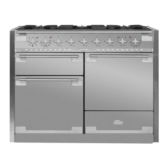
2. Range Overview DocAUS.020-0004 - Overview - 110DF - Elan Fig. 2.1 ArtNo.215-0009 - 110 Elan DF The 48” dual fuel range (Fig. 2.1) has the following features: Fig. 2.2 5 gas burners including 1 wok burner (Fig. 2.2) A control panel Glide Out Broiler System™... - Page 9 When you release the control knob, if the burner goes out, Fig. 2.4 the FSD has not been bypassed. Turn the control knob to the OFF position and wait for one minute before you try again, this time making sure to hold in the control knob for slightly longer.
- Page 10 the cradle, make sure that it is supported properly on a burner Fig. 2.12 grate and the wok is sitting level in the cradle (Fig. 2.12). The cradle will get very hot in use – allow plenty of time for it to cool before you pick it up.
- Page 11 Ovens Convection cooking is particularly suitable for batch baking on several shelves at one time and is a good ‘all-round’ References to ‘left-hand’ and ‘right-hand’ ovens apply as function. It may be necessary to reduce the temperature by viewed from the front of the appliance. approximately 25 °F/10°C for recipes previously cooked in a conventional oven.
- Page 12 Browning Function This function uses the element in the top of the oven To thaw small items in the oven Defrost only. It is a useful function for the browning or without heat. finishing of pasta dishes, vegetables in sauce, A full cooking function, even heat Convection throughout, great for baking.
- Page 13 Accessories Fig. 2.21 Fig. 2.22 Oven Shelves The range is supplied with the following: • 2 standard shelves (Fig. 2.21) • 1 drop shelf (Fig. 2.22) • 2 telescopic shelves with runners (Fig. 2.23) Fig. 2.23 Fig. 2.24 • 2 sets of side supports (Fig. 2.24) The oven shelves are retained when pulled forward but can be easily removed and refitted.
- Page 14 To Fit the Telescopic Shelf Runners Fig. 2.25 With the runner arm in the closed position locate the opening of the upper rear slot onto the side support (Fig. 2.25). DO NOT locate any further than the opening at this point. Lift the front of the runner arm to locate the front slot against the side support (Fig.
- Page 15 Storage The bottom drawer is for storing cooking utensils. To open, simply push the drawer in and release. Flammable materials should not be stored in an oven, the range storage drawer or near the cooktop burners. This includes paper, plastic and cloth items, such as cookbooks, plasticware and towels, as well as flammable liquids.
-
Page 16: Cooking Tips
3. Cooking Tips Cooking with a Multi-function Oven When the oven is on, DO NOT leave the door open for longer than necessary, otherwise the knobs may get very hot. REMEMBER: not all modes are suitable for all food types. The •... -
Page 17: Cooking Table
4. Cooking Table DocNo.031-0004 - Cooking table - electric & fan single cavity The oven control settings and cooking times given in the table below are intended to be used as a guide only. Individual tastes may require the temperature to be altered to provide a preferred result. ArtNo.050-0019 - Albertine SC Food is cooked at lower temperature in a fan oven than in a conventional oven. -
Page 18: Cleaning Your Range
5. Cleaning Your Range Essential Information Before thorough cleaning, turn off the circuit breaker. Allow the range to cool. After cleaning remember to switch on the circuit breaker before using the range. NEVER use paint solvents, caustic cleaners, biological powders, bleach, chlorine based bleach cleaners, coarse abrasives or salt. - Page 19 Stainless Steel Main Top Fig. 5.1 Lift away pots or pans from main top. Remove grates from spillage area and carefully place in a sink of warm soapy water. Wipe loose debris from main top. Avoid using any abrasive cleaners including cream cleaners on brushed stainless steel surfaces.
- Page 20 Glide-out Broiler™ Fig. 5.5 Before you remove any of the broiler parts for cleaning, make sure that they are cool, or use oven gloves. Wash the broiler pan, trivet and broiler tray in hot soapy water. Alternatively, wash the broiler pan in a dishwasher. After broilling meats or any foods that soil, leave to soak for a few minutes in the sink immediately after use.
- Page 21 Hot soapy water, soft cloth. Any stubborn stains remove gently with a Cooktop surface Enamel or stainless steel nylon scourer and AGA Enamel and AGA Chrome & Steel Cleaner respectively. Mildly abrasive cleaner such as AGA Burner grates & top of burner heads Porcelain enamel Enamel Cleaner.
-
Page 22: Troubleshooting
6. Troubleshooting We DO NOT recommend corrosive or caustic Ignition or cooktop burners faulty cleaners as these may damage your range. Is the power on? The knobs get hot when I use the oven, can I avoid this? Are the sparker (ignition electrode) or burner holes blocked by debris? Yes, this is caused by heat rising from the oven, and heating them up. - Page 23 Oven not coming on Fig. 6.1 Is the power on? If not there may be something wrong with the power supply. Is the range supply on at the circuit breaker? Have you set a cooking function? Oven temperature getting hotter as the range gets older ArtNo.320-0006b -Mercury oven door hinge adjustment If turning the knob down has not worked or only worked for a short time then you may need a new...
-
Page 24: Service And Parts
If you are still having difficulty, please contact Tech Support at 800-223-3900 or email techsupport@agamarvel.com. Please Note For warranty information or to register your AGA range, go to www.aga-ranges.com. You may also refer to the warranty document provided with the appliance or contact Customer Service at 800-223-3900. -
Page 25: Installation
INSTALLATION Check the appliance is electrically safe when you have finished. 8. Installation Regulations Installation Safety Instructions Installation of this range must conform with local codes, or in Improper installation, adjustment, alteration, the absence of local codes, with the National Fuel Gas Code, service or maintenance can cause injury or property ANSI Z223.1/NFPA.54, latest edition. - Page 26 INSTALLATION Check the appliance is electrically safe when you have finished. Location of the Range Additional materials you may need: Gas line shut-off valve. Do not locate the range where it may be subject to strong drafts. Any openings in the floor or wall behind the range Pipe joint sealant or UL-approved pipe thread tape with should be sealed.
- Page 27 INSTALLATION Check the appliance is electrically safe when you have finished. Positioning the Range Fig. 8.1 Fig. 8.1 and Fig. 8.2 show the minimum recommended ” ” distance from the range to nearby surfaces. 30 mm 30 mm 31 ½” The range should not be placed on a base.
- Page 28 INSTALLATION Check the appliance is electrically safe when you have finished. Moving the Range Fig. 8.1 The range is very heavy. Take great care. On no account try and move the range while it is plugged into the electricity or gas supply. We recommend two people maneuver the range.
-
Page 29: Fitting The Flue, Flue Vent And Side Panels
INSTALLATION Check the appliance is electrically safe when you have finished. 9. Fitting the Flue, Flue Vent and Side Panels Checking the Parts: Fig. 9.1 Flue Flue Vent Flue Fan Assembly Fig. 9.2 Fitting the Flue Remove the four screws from the broiler flue opening (Fig. - Page 30 INSTALLATION Check the appliance is electrically safe when you have finished. Fitting the Cooling Fan Box Fig. 9.3 Remove the six screws where the cooling fan box will be fixed Fig. 9.3. The shape of the molex plug should match the socket. Gently connect the molex plug to the molex connector socket Fig.
- Page 31 INSTALLATION Check the appliance is electrically safe when you have finished. Fitting the Side Panel Rear Checking the Parts: Retaining Brackets Side panel rear retaining Side panels brackets Located at the bottom left and right rear corner of the A051761 - Right-hand A052064 - Right-hand range, remove the two screws (Fig.
- Page 32 INSTALLATION Check the appliance is electrically safe when you have finished. Fitting the Side Panels Check everything is firmly connected and tighten the screw in the flue vent to secure the side panel in Loosen the screw in the flue vent (Fig. 9.10). position (Fig.
- Page 33 INSTALLATION Check the appliance is electrically safe when you have finished. Fitting the Front Mounting For safety’s sake make sure the drawer runners are out of the way. Brackets On the front of the range base there are two mounting Open the right-hand oven door and pull the drawer out plates.
- Page 34 INSTALLATION Check the appliance is electrically safe when you have finished. Fitting the Bottom Panel (Toe kick) Adjust the bottom panel to set the gap between the side panels and doors equally (Fig. 9.18). When it is Tilt the bottom of the panel slightly to locate the lower positioned correctly, use a suitable flat open-ended slots onto the washers (Fig.
- Page 35 INSTALLATION Check the appliance is electrically safe when you have finished. Fitting the Drawer Fig. 9.20 To fit the drawer, pull the side rails fully out (Fig. 9.20). Carefully move the drawer back between the rails and rest it on the side rails. At each side, hold the front of the drawer and pull the side rail forward so that the clips click into position, holding the drawer to the side rails (Fig.
- Page 36 INSTALLATION Check the appliance is electrically safe when you have finished. Fitting the Restraint Chain and Fig. 9.22 Anti-Tip Device Restraint chain A range using a flexible gas connector must be secured with a suitable restraint chain and anti-tip device. When fitting the restraint chain it should be kept as short as is practicable and fixed firmly to the rigid pipe at the top, right-hand, rear of the range;...
-
Page 37: Removing The Side Panels
INSTALLATION Check the appliance is electrically safe when you have finished. 10. Removing the Side Panels Removing the Bottom Panel You will need the following equipment to remove the side panels: (Plinth/Toekick) • Cross-head screwdriver After removing the drawer open the left-hand oven •... - Page 38 INSTALLATION Check the appliance is electrically safe when you have finished. Removing the Side Panels Loosen one screw in the vent (Fig. 10.5). Push forward the side panel so that it moves away from the flue vent and the retaining washer (Fig. 10.6). Inside the top of the side panel top are two tabs.
-
Page 39: Gas Connection
INSTALLATION Check the appliance is electrically safe when you have finished. 11. Gas Connection Installation of this range must conform with local codes or, in Fig. 11.1 the absence of local codes, with the National Fuel Gas Code, ANSI Z223.1-latest edition. 9 ¾”... - Page 40 INSTALLATION Check the appliance is electrically safe when you have finished. Connect the Range to the Gas Supply When using test pressures greater than ½ psi (3.5 kPa) to pressure test the gas supply system of the residence, Shut off the main gas supply valve before disconnecting the disconnect the range and individual shut-off valve from the old range and leave it off until the new hookup has been gas supply piping.
-
Page 41: Conversion To Lp Gas
INSTALLATION Check the appliance is electrically safe when you have finished. 12. Conversion to LP Gas Important Fig. 12.1 • Observe all governing codes and ordinances. Burner head • The range must be properly grounded. Burner ring • Save these instructions for the local electrical inspector’s Brass venturi use. - Page 42 INSTALLATION Check the appliance is electrically safe when you have finished. To Install the new orifices; see Table 12.1 for orifice details. Fig. 12.4 Insert the new orifice into the open end of the rubber tube which is attached to the socket wrench. Screw into the orifice carrier as far as possible and lift the socket wrench away (Fig.
- Page 43 INSTALLATION Check the appliance is electrically safe when you have finished. Reassemble Fig. 12.8 If you have lifted the maintop, carefully lower it onto the range. The burners are protected against the burner flames going out by Flame Supervision Devices (FSD’s). Take care when lowering the maintop to locate the FSD sensor probes (Fig.
- Page 44 INSTALLATION Check the appliance is electrically safe when you have finished. Stick on Labels Fig. 12.14 Complete the conversion label (kit number A060048) and K085791 This appliance was converted on stick it next to the ratings label inside the drawer cavity to month -day -year...
-
Page 45: Electrical Connection
INSTALLATION Check the appliance is electrically safe when you have finished. 13. Electrical Connection Have your appliance properly installed and grounded by a Fig. 13.1 qualified technician. The installation must conform with local codes or in the absence of local codes in accordance with the National Fuel Gas Code, ANSI Z223.1/NFPA 54 or, in Canada, the Natural Gas and Propane Installation Code, CSA B149.1 and in addition the National Electrical Code ANSI/NFPA No. - Page 46 INSTALLATION Check the appliance is electrically safe when you have finished. Connecting if the Supplied Cord and Fig. 13.3 Plug is not Suitable Terminal Block Terminal Clamp To remove the electrical connection cover (Fig. 13.1), remove the 4 screws (Fig. 13.2). Black White 4-Wire Conduit Installation...
- Page 47 INSTALLATION Check the appliance is electrically safe when you have finished. Attach the ground strap to the neutral and earth Fig. 13.9 Terminal Block Terminal Clamp terminal post supplied on the cooker back plate (Fig. 13.9). Tighten the fixings to 3 - 4 Nm (2.20 - 2.95 ft lb). Connect the power cord wire to the terminal block and tighten to 3 - 4 Nm (2.20 - 2.95 ft lb).
-
Page 48: Final Fitting
INSTALLATION Check the appliance is electrically safe when you have finished. 14. Final Fitting Fitting the Handrail Fig. 14.1 Retaining screw Using the 2 mm Allen key supplied, loosen the two retaining screws in the base and side of the handrail support. -
Page 49: Circuit Diagram
15. Circuit Diagram P026819 P026819 P029549 P033458 P028728 P033458 Code Description Code Description Code Color Blue Broiler Thermostat Right-hand oven thermostat Brown Broiler Controller Right-hand oven switch block Black Broiler Elements Right-hand oven element Orange Left-hand oven thermostat Right-hand oven fan motor Left-hand oven switch block Ignition switches Violet... -
Page 50: Technical Data
16. Technical Data INSTALLER: Please leave these instructions with the user. DATA BADGE LOCATION: Inside base drawer of cavity. Remove the drawer (see Overview > Storage for details). COUNTRY OF DESTINATION: USA, Canada. Connections Electric 240 V 60 Hz ArtNo280-0090 Drawer Cavity & Badges ½”... - Page 51 Notes...
- Page 52 AGA Marvel 1260 E. VanDeinse St. Greenville, MI 48838 Business (616) 754-5601 Fax (616) 754-9690 Toll Free Telephone 800-223-3900 www.aga-ranges.com...
Need help?
Do you have a question about the AEL48DF-SS and is the answer not in the manual?
Questions and answers