
Related Manuals for AGA AMPRO36DF


Summary of Contents for AGA AMPRO36DF
- Page 1 Professional 90 Dual Fuel User Guide & Installation & Service Instructions U110246 - 03...
-
Page 2: Table Of Contents
Contents 1. Before You Start... Installation In Case of Fire Regulations To Prevent Fire or Smoke Damage Installation Safety Instructions Wear Suitable Clothing Converting to Propane Gas Use Only Dry Potholders or Oven Gloves Location of the Range Important Safety Notice and Warning Positioning the Range Proper Installation Fitting the Oven Handle... -
Page 3: Before You Start
1. Before You Start... Read all instructions before using this appliance. Save Many plastics will burn and most are damaged by heat. Keep these instructions for future reference. plastic items away from parts of the range that may become warm or hot. Do not leave plastic items on the cooktop as Have your appliance properly installed and grounded by they may burn, melt or soften if left too close to a vent or a a qualified technician in accordance with the National... -
Page 4: Wear Suitable Clothing
To avoid risk of electrical shock, personal injury, or death, primarily to the incomplete combustion of natural gas or make sure your range has been properly grounded and liquid petroleum (LP) fuels. Properly adjusted burners will always disconnect it from the main power supply before minimize incomplete combustion. -
Page 5: Use The Right Size Pan
Use the Right Size Pan Clean only parts listed in this User Guide. Before self-cleaning the oven: remove the broiler This appliance is equipped with burners of different sizes. pans, side racks, sliding rack, divider and all other Use utensils with flat bottoms. Do not use unstable pans and utensils. - Page 6 Take care when touching range, to minimize the When an oven is on, do not use the top of the flue (the holes possibility of burns, always be certain that the along the back of the range) for warming plates, dishes, controls are in the OFF position and that it is cool drying dish towels or softening butter.
-
Page 7: Range Overview
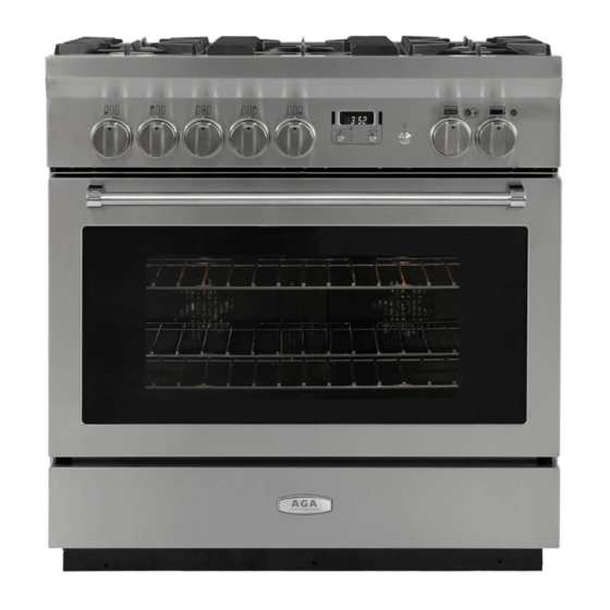
4. Range Overview DocNo.025-0101 - Overview - 90 DF SC - Prof+ FX Fig. 4.1 PROFESSIONAL ArtNo.270-0029 - Prof+ 90SC annotated The dual fuel single cavity range (Fig. 4.1) has the following Fig. 4.2 features: 5 hotplate burners A control panel incorporating a timer A multi-function oven A storage drawer Cooktop Burners... -
Page 8: Griddle (Optional Extra)
The igniter should spark and light the gas. Keep holding the Fig. 4.3 knob pressed in to let the gas through to the burner for about ten seconds. If, when you let go of the control knob, the burner goes out, then the FSD has not been bypassed. -
Page 9: Wok Cradle (Optional Extra)
Position the griddle over the hotplate burners resting on the Fig. 4.10 grates (Fig. 4.9). Check that it is securely located. The griddle can be lightly brushed with cooking oil before use. Light the hotplate burners. Adjust the flame heights to suit. -
Page 10: Multi-Function Oven Modes
4.14 shows the control set for conventional oven cooking. ArtNo.272-0017 Turn the oven temperature knob to the temperature you 90 Aga Professional - MF oven controls Fig. 4.13 need. The oven heating light will glow until the oven has reached the temperature you selected. It will then cycle on and off during cooking as the oven maintains the selected temperature (Fig.2-15). - Page 11 Convection Oven Fig. 4.16 This function operates the fans and the heating element around them (Fig. 4.18). An even heat is produced throughout the oven, allowing you to cook large amounts quickly. Convection oven cooking is particularly suitable for multi- rack cooking and is a good ‘all-round’...
- Page 12 Conventional Oven (Top and Base Heat) Fig. 4.21 This function combines the heat from the top and base elements (Fig. 4.21). It is particularly suitable for roasting and baking pastry, cakes and biscuits. Food cooked on the top rack will brown and crisp faster than on the lower rack, because the heat is greater at the top of the oven than at the base, as in ‘fan assisted oven’...
-
Page 13: The Clock
The Clock Fig. 4.24 ArtNo.300-0005 2BC The clock must be set to the time of day before the oven minute minder setting will work. 1. Once the cooker is connected and switched on, the display will start to flash. 2. To set the time, turn and hold the Timer (A) knob to the Clock (C) setting and at the same time turn the Adjusting (B) knob either clockwise or counter-clockwise (Fig. - Page 14 To Stop the Multifunction Oven at a Specific ArtNo.301-0008 2BC Fig. 4.29 Time of Day Stopping the oven 2 You have set the required temperature and function mode for the Multifunction Oven and you would like the Multifunction Oven to automatically stop. TOP TIP Make a note of the current time so you do not forget.
- Page 15 To Start and Stop the Multifunction Oven ArtNo.301-0007 2BC Fig. 4.35 The Multifunction Oven allows you to automatically start and Stopping the oven 1 stop by a combination of the length of the cooking time and the stop time. Giving you the flexibilty to cook casseroles etc while you are out.
-
Page 16: Accessories
Accessories Fig. 4.40 Fig. 4.39 Oven Racks ArtNo.326-0014 - Cradle rack (Falcon) Each range is supplied with the following: 1 broiler pan rack with telescopic runners (Fig. 4.39) 2 flat racks with telescopic runners (Fig. 4.40) 2 broiler pans with grids (Fig. 4.41) Fig. -
Page 17: Oven Light
To Remove and Refit the Ladder Rack Supports Fig. 4.47 Lift the ladder support hooks out of the two locating holes in the oven side (or divider) before lifting the support clear of the bottom ladder restraint. ArtNo.320-0017 Refit by inserting the bottom of the ladder into the restraint Main oven light before fitting the hooks through the locating holes. -
Page 18: Cooking Tips
3. Cooking Tips Cooking with a Multi-function Oven General Oven Tips Remember: not all modes are suitable for all food types. The The wire racks should always be pushed firmly to the back of oven cooking times given are intended for a guide only. the oven. -
Page 19: Cooking Table
4. Cooking Table The oven control settings and cooking times given in the table below are intended to be used AS A GUIDE ONLY. Individual tastes may require the temperature to be altered to provide a preferred result. Food is cooked at lower temperature in a fan oven than in a conventional oven. When using ArtNo.050-0019 - Albertine SC - Shelf position recipes, reduce the fan oven temperature by 25°F (10 °C) and the cooking time by 5-10 minutes. -
Page 20: Troubleshooting
5. Troubleshooting Cooktop ignition or cooktop burners faulty If there is an installation problem and I don’t get my original installer to come back to fix it who pays? Is the power on? You do. Service organizations will charge for their Are the sparker (ignition electrode) or burner holes service if they are correcting work carried out by your blocked by debris? - Page 21 The timed oven is not coming on when automatic cooking Fig. 5.1 Has the oven knob been left in the OFF position by mistake? Is the oven locked (see above)? Oven temperature getting hotter as the range gets older ArtNo.324-0005 Oven light bulb If turning the knob down has not worked or only worked for a short time then you may need a new thermostat.
-
Page 22: Cleaning Your Range
6. Cleaning Your Range Essential Information Fig. 6.1 Before thorough cleaning, turn off the circuit breaker. Allow the range to cool. After cleaning, remember to switch on the circuit breaker and ArtNo.311-0028 - Burner head off reset the clock before re-using the range. Never use paint solvents, caustic cleaners, biological powders, bleach, chlorine based bleach cleaners, coarse abrasives or salt. -
Page 23: Griddle (Optional Extra)
Avoid using any abrasive cleaners including cream Fig. 6.4 cleaners on brushed stainless steel surfaces. Never use caustic or abrasive cleaners as these will damage the surface. Griddle (Optional Extra) Always clean the griddle after use. Allow to cool completely before removing. - Page 24 Refit in the reverse order, making sure to push the rack down Fig. 6.7 onto the runner arms. To Remove and Refit the Ladder Rack Supports Lift the ladder support hooks out of the two locating holes in the oven side (or divider) before lifting the support clear of the bottom ladder restraint.
-
Page 25: Cleaning Table
Cleaners listed are available from supermarkets or electrical Hot soapy water and soft cloth. ArtNo.050-0070 - Cleaning table AGA Professional retailers as stated. For enamelled surfaces use a cleaner that is Mildly abrasive cleaner with a soft Door inner Glass approved for use on vitreous enamel. - Page 26 WARNING! If the information in this manual is not followed exactly, a fire or explosion may result causing property damage, personal injury or death. Do not store or use gasoline or other flammable vapors and liquids in the vicinity of this or any other appliance. WHAT TO DO IF YOU SMELL GAS Do not try to light any appliance.
-
Page 27: Installation
INSTALLATION Check the appliance is electrically safe and gas sound when you have finished. 7. Installation Regulations Important! • Remove all packing material and literature from oven Installation of this range must conform with local codes, or in before connecting gas and electrical supply to range. the absence of local codes, with the National Fuel Gas Code, ANSI Z223.1/NFPA.54, latest edition. - Page 28 INSTALLATION Check the appliance is electrically safe and gas sound when you have finished. This will allow the range to be moved for cleaning or Checking the parts: servicing. Also, make sure your floor covering will withstand 6 grates Allen key 180 °F (80 °C);...
-
Page 29: Positioning The Range
INSTALLATION Check the appliance is electrically safe and gas sound when you have finished. Positioning the Range Fig. 7.1 Fig. 7.1 shows the minimum recommended distances and clearances from the range to nearby surfaces. Min 35½” (90 cm) - 36“ (91 cm) For Canada, min 36 / ”... -
Page 30: Fitting The Oven Handle
(Fig. 7.3). ArtNo.063-0019 - 90 - SC - Aga Professional - Removing the door Moving the Range The range is very heavy. Take great care. -
Page 31: Installing The Flue Grille
INSTALLATION Check the appliance is electrically safe and gas sound when you have finished. Lowering the Two Rear Rollers Fig. 7.6 To adjust the height of the rear of the range, first fit a 13 mm spanner or socket wrench onto the hexagonal adjusting nut (Fig. - Page 32 INSTALLATION Check the appliance is electrically safe and gas sound when you have finished. Adjust and lock the inner anti-tip bracket to give a ” (3 mm) Fig. 7.10 Stability bracket Anti-tip bracket clearance above the engagement edge in the back of the range (Fig.
-
Page 33: Electrical Connection
INSTALLATION Check the appliance is electrically safe and gas sound when you have finished. Electrical Connection Fig. 7.14 When installed the range must be electrically grounded in accordance with local codes or; in the absence of local codes with the National Electrical Code ANSI/NFPA 70, latest edition. 16”... - Page 34 INSTALLATION Check the appliance is electrically safe and gas sound when you have finished. 4-Wire Conduit Installation Fig. 7.16 Disconnect the supplied power cord from the terminal block and ground post. Keep the terminal block parts; you will need them. Remove the strain relief clamp from the power cord and remove the power cord and strain relief clamp from the mounting bracket (Fig.
- Page 35 INSTALLATION Check the appliance is electrically safe and gas sound when you have finished. Attach the ground strap to the ground and center terminal of Fig. 7.22 the connector block. The neutral or ground wire of the power cord must be connected to the neutral terminal located in the center of the ArtNo.280-0039 Reducer Plate connector block.
-
Page 36: Gas Connection
INSTALLATION Check the appliance is electrically safe and gas sound when you have finished. Gas Connection Fig. 7.25 Installation of this range MUST conform with local codes or, in the absence of local codes, with the National Fuel Gas Code, ANSI Z223.1-latest edition. - Page 37 INSTALLATION Check the appliance is electrically safe and gas sound when you have finished. Connect the Range to the Gas Supply Fig. 7.28 Shut off the main gas supply valve before disconnecting the Appliance old range and leave it off until the new hookup has been Flexible connector Adaptor gas inlet...
-
Page 38: Seal The Openings
INSTALLATION Check the appliance is electrically safe and gas sound when you have finished. Seal the Openings Fig. 7.29 Seal any openings in the wall behind the range and in the floor under the range when hookups are completed. IMPORTANT: When all connections are completed make sure the flow of combustion and ventilation air to the range is unobstructed. -
Page 39: Range Operational Checks
INSTALLATION Check the appliance is electrically safe and gas sound when you have finished. Range Operational Checks Refitting the Range Reverse the above procedure to refit. If the gas line has been Oven Check disconnected, check for gas leaks after reconnection. Turn on the oven and check that the oven fans start to turn Note: A suitably qualified person should disconnect and and that the oven starts to heat up. -
Page 40: To Fit The Drawer
INSTALLATION Check the appliance is electrically safe and gas sound when you have finished. To fit the drawer To remove the drawer... -
Page 41: Conversion To Another Gas Important
If the appliance is to be converted this must be done before installation. The conversion must be performed by a qualified ArtNo.272-0025 - 90 Aga Professional - Control panel removal LP gas installer. After conversion the installation must comply with the relevant regulations and also the local electricity supply company requirements. - Page 42 CONVERSION Check the appliance is electrically safe and gas sound when you have finished. Remove the electrical connections from the rear. Taking care ArtNo.0102-0011 - Screwing Fig. 8.3 not to damage the control panel, and protecting it with cloth the control valve bypass screw for example, rest it on the open oven door.
-
Page 43: Stick On Label
CONVERSION Check the appliance is electrically safe and gas sound when you have finished. Type 2 Fig. 8.8 The regulator has a bayonet mounted top cap (Fig. 8.8). Using a small coin, press in and turn the cap to remove it. Turn the cap over so that the letters “LP”... -
Page 44: Circuit Diagram
9. Circuit Diagram A2/B1 B2 Code Description Code Description Code Color Multi-function oven master switch Oven protect thermostat Blue Multi-function oven drone switch Oven neon Brown Oven thermostat Oven light Black Oven front switch Oven light switch Orange Right-hand oven base element Door lock neon Right-hand oven top outer element Ignition spark generator... -
Page 45: Technical Data
10. Technical Data INSTALLER: Please leave these instructions with the user. RATING PLATE LOCATION: Inside base drawer of cavity. Remove the drawer (see ‘Overview’ > ‘Storage’ for details). COUNTRY OF DESTINATION: USA, Canada. Connections Electric 240 V 60 Hz ArtNo280-0090 Drawer Cavity & Badges ½”... - Page 46 AGA warrants the oven heating elements against defects in material or workmanship for an additional two years. These parts will be repaired or replaced at the option of AGA without charge, but you pay for labor and transportation subject to the terms and conditions set out below.
- Page 47 Notes...
- Page 48 AGA Marvel 1260 E. VanDeinse St. Greenville, MI 48838 Business (616) 754-5601 Fax (616) 754-9690 Toll Free Telephone 800-223-3900 www.aga-ranges.com...
Need help?
Do you have a question about the AMPRO36DF and is the answer not in the manual?
Questions and answers