Table of Contents
Advertisement
Quick Links
Contents
Chapter 1 Specification ............................................. 8
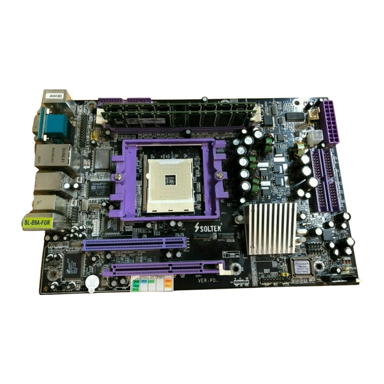
1-1 B9A-FGR Layout ......................................................................9
1-2 Chipset System Block Diagram ........................................... 10
1-3 Mainboard Specification Table ............................................ 11
1-4 Mainboard Specifications .................................................... 12
1-4.1 CPU ................................................................................................ 12
1-4.2 System Chipsets ........................................................................... 12
1-4.3 Memory ......................................................................................... 12
1-4.4 BIOS ............................................................................................... 12
1-4.5 AGP (Accelerated Graphics Port) interface .......................... 13
1-4.6 Multi-I/O Functions .................................................................... 13
1-4.7 SATA and SATA RAID Interface .............................................. 13
1-4.8 Advanced System Power Management .................................... 14
1-4.9 CMI8768 8-channel Audio controller on board .................... 14
1-4.10 Hardware Monitor on board ................................................... 14
1-4.11 IEEE 1394 Interface .................................................................. 14
1-4.12 Gigabit Ethernet Controller on board ................................... 15
1-4.13 Front Panel Connector ............................................................. 15
1-4.14 Form Factor ................................................................................ 15
Chapter 2 Hardware Setup ..................................... 16
2-1 CPU Installation with Socket 754 ....................................... 17
2-2 Socket 754 Athlon 64 Fan Installation ............................... 18
2-3 Memory Installation ............................................................. 20
2-3.1 How to tackle the memory Modules: ....................................... 20
2-3.2 To Install DDR SDRAM Module .............................................. 20
2-4 ATX Power Supply Installation .......................................... 21
2-5 AGP Slot Installation ............................................................ 21
2-6 IDE Connector Installation ................................................. 22
2-7 Floppy Drive Connector Installation ................................. 23
Contents
4
Advertisement
Table of Contents

Related Manuals for SOLTEK B9A-FGR


Summary of Contents for SOLTEK B9A-FGR
-
Page 1: Table Of Contents
Contents Contents Chapter 1 Specification ..........8 1-1 B9A-FGR Layout ..............9 1-2 Chipset System Block Diagram ........... 10 1-3 Mainboard Specification Table ..........11 1-4 Mainboard Specifications ............ 12 1-4.1 CPU ....................12 1-4.2 System Chipsets ................12 1-4.3 Memory ..................12 1-4.4 BIOS .................... - Page 2 Contents 2-8 Serial ATA Connectors Installation ........24 2-9 Jumper Setting ............... 25 2.9.0 How to tackle the Jumpers: ............26 2-9.1 JBAT1: Clear CMOS ..............27 2-9.2 JKB1 + J2 : USB Keyboard / Mouse Wake Up ...... 27 2-10 Other Connectors Configuration ........
- Page 3 5-0-2 Disk Array Member ..............77 5-0-3 Disk Array Types Supported by nForce3 250Gb ....77 5-1. SATA / IDE connectors on B9A-FGR ....... 78 5-2. Enable RAID function in the BIOS ........78 5-3. About the NVRAID BIOS ........... 79 5-4.
-
Page 4: Chapter 1 Specification
SL-B9A-FGR Chapter 1 Specification Introduction This mainboard features an integration of the powerful AMD Athlon 64 CPU and the single chip nVIDIA nForce3 250Gb, with which the whole system performance supports HyperTransport Bus up to 800MHz. nVIDIA nForce3 250Gb supports on-board AMD Athlon 64 processor to implement HyperTransport 800MHz, the AGP 8X/4X interface, PCI interface, IEEE 802.3 nVIDIA MAC, the LPC Super I/O, the USB 2.0... -
Page 5: B9A-Fgr Layout
Chapter 1 Specification 1-1 B9A-FGR Layout C-Media CMI 8768 JAUD1 JKB1 CICADA Fan2 Winbond SimpliPHY W83627HF CIS8201 VT6307S SATA2 SATA1 nVIDIA nFORCE3 250 Gb JBAT1 USB3 IDE2 +12V Power USB4 Fan1 Main Power Fan3 IDE1... -
Page 6: Chipset System Block Diagram
SL-B9A-FGR 1-2 Chipset System Block Diagram DDR 400/333/266 Socket 754 System Memory AMD Athlon64 Hyper Transport 800MHz PATA RAID AGP 8X/4X 4 IDE AGP Slot ATA 133/100/66 Devices PCI Bus 1 PCI Slot SATA RAID 2 SATA ports nVIDIA 8-channel... -
Page 7: Mainboard Specification Table
Chapter 1 Specification 1-3 Mainboard Specification Table SL-B9A-FGR Specifications and Features Socket 754 for AMD Athlon 64 CPUs System chipset nVIDIA nForce3 250 Gb Award BIOS BIOS DDR 400/333/266 SDRAM, up to 2GB in 2 DDR Memory DIMM slots AGP 8X/4X mode only; 1 AGP Slot on board... -
Page 8: Mainboard Specifications
SL-B9A-FGR 1-4 Mainboard Specifications 1-4.1 CPU CPU Socket 754 on board, supporting AMD Athlon 64 processors, imple- menting up to 800MHz Hyper Transport Speed (System Bus) designed to be capable of operating up to 1600MT/s with a resulting bandwidth of up to 6.4 Gbytes/s and integrated Memory Controller which supports up to DDR SDRAM at 200MHz 1-4.2 System Chipsets... -
Page 9: 1-4.5 Agp (Accelerated Graphics Port) Interface
Chapter 1 Specification 1-4.5 AGP (Accelerated Graphics Port) interface AGP Controller is embedded on board, supporting: • 1.5V (8x/4x) power mode • 8X 66MHz AD and SBA signaling; AGP pipelined split-transaction longburst transfers up to 2GB/sec. • One AGP Slot on board, AGP v3.0 compliant 1-4.6 Multi-I/O Functions •... -
Page 10: 1-4.8 Advanced System Power Management
• Hardware Monitor supported by LPC I/O Winbond W83627HF, pro- viding monitoring functions on hardware voltage, temperatures and fan speeds. • Utility Software Soltek Hardware Monitor for displaying monitor sta- tus is enclosed in Support CD for user’s installation. 1-4.11 IEEE 1394 Interface... -
Page 11: 1-4.12 Gigabit Ethernet Controller On Board
Chapter 1 Specification 1-4.12 Gigabit Ethernet Controller on board Gigabit Ethernet Controller CICADA CIS8201 on board: • Supporting 10/100/1000Mb data transfer • Supporting Wake On LAN function through the on-board RJ45 LAN Connector • LAN Driver enclosed in Support CD for user’s installation. 1-4.13 Front Panel Connector •... -
Page 12: Chapter 2 Hardware Setup
SL-B9A-FGR Chapter 2 Hardware Setup To Get Things Ready for Hardware Setup ! 1. We recommend to install your CPU before any other components. For detailed installation instructions of processor, you can also refer to the pamphlet enclosed in your CPU package. -
Page 13: Cpu Installation With Socket 754
Chapter 2 Hardware Setup 2-1 CPU Installation with Socket 754 This series is built with CPU Socket 754 supporting the AMD CPUs Athlon 64: • Follow the steps described in this section to install CPU into the on- board Socket 754. •... -
Page 14: Socket 754 Athlon 64 Fan Installation
SL-B9A-FGR 2-2 Socket 754 Athlon 64 Fan Installation When setting up Socket 754 cooling fan on B9A-FGR, the Heat Glue should first be applied to the Heat Sink. Then locate the Fan Latch with a Lever to the Back Panel side. - Page 15 Chapter 2 Hardware Setup 5. Fix the Metal Latch without Lever to Fan Base. 6. Fix the Metal Latch with Lever to Fan Base. 7. Now pull over the Metal Lever to other side and press it down so as to lock the cooling Fan to the socket base.
-
Page 16: Memory Installation
SL-B9A-FGR 2-3 Memory Installation 2-3.1 How to tackle the memory Modules: • Make sure to unplug your power supply before adding or removing memory module. Failure to do so may cause severe damage to both your mainboard and the memory module. -
Page 17: Atx Power Supply Installation
Chapter 2 Hardware Setup 2-4 ATX Power Supply Installation To set up Power Supply on this mainboard: Both main Power Connector and the +12V Power Connector should all be connected to a V2.03 ATX Power Supply so as to boot system with sufficient power. -
Page 18: Ide Connector Installation
SL-B9A-FGR 2-6 IDE Connector Installation IDE1 and IDE2 are 2 IDE connectors supporting 4 IDE devices for up to 133MB/s data transfer. IDE1 and IDE2 are also supported by nForce3 to support IDE RAID system setup with 4 IDE hard disks. -
Page 19: Floppy Drive Connector Installation
Chapter 2 Hardware Setup 2-7 Floppy Drive Connector Installation To install FDC, you should connect the end of FDC cable with single connector to the board, and connect the other end with two connectors to the floppy drives. C-Media CMI 8768 JAUD1 JKB1 CICADA... -
Page 20: Serial Ata Connectors Installation
SL-B9A-FGR 2-8 Serial ATA Connectors Installation The Serial ATA is designed to improve the Parallel ATA with the capabil- ity of Hot Plug and offer a data bandwidth of 150Mbytes/second. It also reduce voltage and pin count and can be implemented with thin cables which improve the inner ventilaton of PC cases. -
Page 21: Jumper Setting
Chapter 2 Hardware Setup 2-9 Jumper Setting The following diagram show the location and setting of jumper block on the mainboard. JKB1 + J2 : USB Keyboard / Mouse Wake Up 1-2 closed (default) Disabled JKB1 2-3 closed Enabled JKB1 C-Media CMI 8768 JAUD1... -
Page 22: How To Tackle The Jumpers
SL-B9A-FGR 2.9.0 How to tackle the Jumpers: A 2-pin Jumper A 3-pin Jumper If a pin-header (of 2 or more pins) is designed in such a way that its pins can be closed or linked together to The conductor inside the cap set up a specific function, this header links two header-pins together. -
Page 23: 2-9.1 Jbat1: Clear Cmos
Chapter 2 Hardware Setup 2-9.1 JBAT1: Clear CMOS When you have problem with rebooting your system, you can clear CMOS data and restore it to default value. To clear CMOS with Jumper JBAT1, please follow the steps below: 1. Power off system. 2. -
Page 24: Other Connectors Configuration
SL-B9A-FGR 2-10 Other Connectors Configuration This section lists out all connectors configurations for users’ reference. 2-10.1 Onboard FAN Connectors Void C-Media Sensor CMI 8768 JAUD1 JKB1 +12V CICADA Fan2 Winbond SimpliPHY W83627HF +12V CIS8201 VT6307S Sensor Conn. No Sensor SATA2... -
Page 25: 2-10.2 Usb Ports And Usb Pin-Headers
Chapter 2 Hardware Setup 2-10.2 USB Ports and USB Pin-headers This mainboard provides 4 USB ports on board supporting various USB devices. In addition, 2 USB pin-header are added on board to provide expansion of four more optional USB ports by using two addi- tional USB Cables. -
Page 26: 2-10.3 Chassis Panel Connectors
SL-B9A-FGR 2-10.3 Chassis Panel Connectors A : PS/2 Mouse H : USB 0 (middle) B : COM1 Port USB 1 (underside) C : LAN Port RJ45 (Top) : USB 2 (middle) D : IEEE1394 Connector USB 3 (underside) E : Center/ Subwoofer Speaker Out... -
Page 27: 2-10.5 Cd-Rom Audio Connectors
Chapter 2 Hardware Setup 2-10.5 CD-ROM Audio Connectors CDIN1 is an audio connector connecting CD-ROM audio to mainboard. C-Media CD-ROM Audio Connector CMI 8768 JAUD1 JKB1 CICADA Fan2 Winbond SimpliPHY W83627HF CIS8201 VT6307S CDIN1 Pin Signal Pin 1 Left Channel SATA2 Pin 2 Pin 3... -
Page 28: 2-10.7 Lan Connector
SL-B9A-FGR 2-10.7 LAN Connector One RJ45 connector is on board for LAN connection, supporting GiGabit Ethernet 10/100/1000Mb data transfer. Red/Orange LED blinks to indicate Yellow LED “On” to indicate that data transmission is undergoing Network hub is in connection in 1000 Base T mode. -
Page 29: 2-10.9 Front Panel Connectors
Chapter 2 Hardware Setup 2-10.9 Front Panel Connectors This Front Panel Connector consists of the following connectors for various front panel supports. When you have fixed the mainboard to the case, join the connectors of this Front Panel Connector to the case Front Panel. -
Page 30: 2-10.10 Ieee 1394A Port/Pin-Header
SL-B9A-FGR 2-10.10 IEEE 1394a Port/Pin-header 1 IEEE1394a Portis built on board for Digital Video Cameras and other devices with 1394a interface. Another IEEE 1394a Pin-header is built on board providing one more 1394a channel on the front Panel. IEEE 1394a Port... -
Page 31: 2-10.11 Printer Port: Lpt1
Chapter 2 Hardware Setup 2-10.11 Printer Port: LPT1 LPT1 is a parallel printer port. LPT1: Printer Port C-Media CMI 8768 JAUD1 JKB1 Pin Assignment CICADA Fan2 Winbond SimpliPHY W83627HF CIS8201 Pin 1 STROBE# Pin 14 AUTOFD# VT6307S Pin 2 LPTDD0 Pin 15 ERROR# Pin 3 LPTDD1 Pin 16 INITA#... -
Page 32: Chapter 3 Software Setup
SL-B9A-FGR Chapter 3 Software Setup Drivers, Utilities and Software Installation • Support CD: This series of mainboards will be shipped with a Support CD which contains those necessary driver files, Application Softwares and some helpful utilities. It is a user-friendly, auto-run CD which will open itself up in a CD-ROM automatically. -
Page 33: To Open Up The Support Cd
Chapter 3 Software Setup 3-1 To Open up the Support CD 1. Please put the Support CD enclosed in your mainboard package into the CD-ROM drive. In a few seconds, the Main Menu will automatic- ally appear, displaying the contents to be installed for this series: 2. -
Page 34: To Install "Nvidia Nforce3 All-In-1 Driver
SL-B9A-FGR 3-2 To Install “nVIDIA nForce3 All-in-1 Driver” 1. Before opening the Support CD, please update Windows 2000 or Windows XP with the latest Service Pack. Otherwise, the installation of USB2.0 driver will not take effect. Following the procedures of opening the Support CD, click to “... - Page 35 Chapter 3 Software Setup 4. Select “Yes” to install nVIDIA IDE SW driver. 9. After all the setup processes are finished, please restart your computer by clicking on “Finish” so as to take the Utility into effect. cáåáëÜ...
-
Page 36: Directx 9 Installation
SL-B9A-FGR 3-3 DirectX 9 Installation Following the installation of nFORCE3 All in 1 Driver, you have to re- start system so that your system can be reconfigured with the driver just installed. When thr restarting procedures finish, please open the Support CD with your CD-ROM to enter the Main Installation Menu. -
Page 37: To Install Cmi8768 Audio Driver
Chapter 3 Software Setup 3-4 To Install CMI8768 Audio Driver Single chip C-Media CMI8768 audio controller on board, supporting up to 8 channel audio output for PC multimedia systems. CMI8768 Audio Driver is provided in Support CD for user’s installation. 3-4.1 Installation 1. - Page 38 SL-B9A-FGR 4. On ”Program Folder” screen, press “Next” to continue. k É ñ í 5. Press “Next” to continue. k É ñ í 6. After the setup process is finished, please check the radial button “Yes, I want to restart my computer now.” And cáåáë...
-
Page 39: 3-4.2 To Verify 6/8-Channel Audio On Volume Control
Chapter 3 Software Setup 3-4.2 To verify 6/8-channel Audio on Volume Control After installation of CMI8768 Audio Driver, you must configure the 5.1 (7.1) Speaker connection to enable the 6/8-channel audio. 1. Connect your on-board Audio Connector to your 6/8-channel speakers as depicted in the figure below: Center/ Subwoofer To Side Speaker Out... - Page 40 SL-B9A-FGR 4. Instantly, the “C-Media PCI 3D Audio Configuration” screen will pop out. Select 6 Speakers or 8 Speakers at the Main Setting and then click ‘’OK’’ to finish configuration.
-
Page 41: To Install Hardware Monitor Utility
Chapter 3 Software Setup 3-5 To Install Hardware Monitor Utility 3-5.1 Installation Hardware Monitor is built on this mainboard. Its installation is pro- grammed to a fully automated mode on Windows 9X/Me/2000/XP. Users can follow the model installation below for its installation on various Windows System. -
Page 42: 3-5.2 Verification
SL-B9A-FGR 3-5.2 Verification 1. After installing Soltek Hardware Monitor, double click “SoltekHM” icon on the desktop to open the main window of the Soltek Hardware Doctor. 2.Then the pop-up screen will show all information about CPU Temperature, Fan Speed and various Voltages. -
Page 43: To Install Usb 2.0 Driver For Windows 2000/Xp
Chapter 3 Software Setup 3-6 To Install USB 2.0 Driver for Windows 2000/XP USB V2.0 with its 480Mb/s transfer rate supports operating system Windows 2000 and Windows XP via the Windows 2000 and Windows XP Service Pack. Users should install the latest Service Pack for Win- dows 2000 or Windows XP. -
Page 44: Chapter 4 Bios Setup
4-5 To upgrade BIOS 4-6 BIOS Setup Attention: The BIOS Setup is subject to constant update without further notice to users. It is necessary for users to update the onboard BIOS by the latest BIOS version provided in our web site: www.soltek.com.tw... -
Page 45: About Bios Setup
Chapter 4 BIOS Setup 4-1 About BIOS Setup BIOS setup is an interactive BIOS program that you need to run when: 1. Changing the hardware of your system. (For example: installing a new Hard Disk etc.) 2. Modifying the behavior of your computer. (For example: changing the system time or date, or turning special features on or off etc.) 3. -
Page 46: To Upgrade Bios
SL-B9A-FGR 4-5 To Upgrade BIOS • System BIOS is incorporated into a Flash memory component. Flash BIOS allows user to upgrade BIOS without the need to replace an EPROM component. • The Upgrade Utility can be loaded on a floppy diskette to execute saving, verifying, and updating the system BIOS. - Page 47 Chapter 4 BIOS Setup Step 4. Type awdflash *.bin /sn/py/cc and then press <Enter> to run BIOS upgrade program. (*.bin depends on your mainboard model and version code. Instead of typing “*”, you should type specific file name for your specific mainboard). Step 5.
- Page 48 SL-B9A-FGR BIOS Update Illustration: (1) Executing the “awdflash.exe pt880.bin” in DOS system, Award Flash Memory Writer Start Screen appears: To input BIOS file name. AwardBIOS Flash Utility V8.24F (C)Phoenix Technologies Ltd. All Rights Reserved For PT880-8237-6A7L2SN9C-00 Date: 09/18/2003 File Name to Program : PT880.BIN Message: Input the (BIOS) file name (2) Press Y if you want to back up your old BIOS.
- Page 49 Chapter 4 BIOS Setup (4) Updating is in progress. Do not turn off power at this moment. AwardBIOS Flash Utility V8.24F (C)Phoenix Technologies Ltd. All Rights Reserved For PT880-8237-6A7L2SN9C-00 Date: 09/18/2003 Flash Type - SST 39SF020 /5V File Name to Program : pt880.bin Writing Flash Memory - 0FE00 OK Write OK No Update...
-
Page 50: Bios Setup
SL-B9A-FGR 4-6 BIOS SETUP --- CMOS Setup Utility Warning and Tips: If changing CMOS Configuration causes difficulty in rebooting system, you can take the following measures: 1. At pressing the power button to reboot, press the “Insert” key at the same time. - Page 51 Attention: The BIOS Setup is subject to constant update without further notice to users. It is necessary for users to update the onboard BIOS by the latest BIOS version provided in our web site: www.soltek.com.tw...
-
Page 52: 4-6.2 Standard Cmos Setup
SL-B9A-FGR 4-6.2 Standard CMOS Setup Standard CMOS Setup records some basic system hardware configuration and sets the system clock and error handling. You only need to modify the configuration values of this option if you want to change your system hardware configuration or when the data stored in the CMOS memory gets lost or damaged. - Page 53 Chapter 4 BIOS Setup Phoenix - AwardBIOS CMOS Setup Utility IDE Primary Master Item Help IDE HDD Auto-Detection Press Enter Menu Level IDE Primary Master Auto Access Mode Auto To auto-detect the HDD’s size, head... Capacity 40022MB on this channel Cylinder 19158 Head...
-
Page 54: 4-6.3 Advanced Bios Features
SL-B9A-FGR 4-6.3 Advanced BIOS Features Advanced BIOS Features improves your system performance or sets up system features according to your preference. Run the Advanced BIOS Features as follows: Choose “Advanced BIOS Features” from the Main Menu and a screen with a list of options will appear:... - Page 55 Chapter 4 BIOS Setup Hard Disk Boot Priority This item allows you to decide the priority of Bootable Hard Disks. Press enter to get into the submenu to choose the prior bootable Hard Disk. Virus Warning When enabled, you receive a warning message if a program (specifically, a virus) attempts to write to the boot sector or the partition table of the hard disk drive.
- Page 56 SL-B9A-FGR Swap Floppy Drive When enabled, floppy drives A and B will be ex- changing without any physical connection and modi- fication on the cables. Boot Up Floppy Seek When enabled, the BIOS tests (seeks) floppy drives to determine whether they have 40 or 80 tracks. Only 360-KB floppy drives have 40 tracks;...
-
Page 57: 4-6.4 Advanced Chipset Features
Chapter 4 BIOS Setup 4-6.4 Advanced Chipset Features Choose “Advanced Chipset Features” from the Main Menu and a list of option will appear: Phoenix - AwardBIOS CMOS Setup Utility Advanced Chipset Features Item Help DRAM Clock/Drive Control Press Enter Menu Level CPU OverClock in MHz AGP OverClock in MHz AGP Aperture Size (MB) - Page 58 SL-B9A-FGR Min RAS# active time This value appears when “DRAM Timing Setting by” (tRAS) is set at “Manual”. Choices: Auto; 5~15 Bus Clocks Precharge to Active This value appears when “DRAM Timing Setting by” (Trp) is set at “Manual”. Choices: Auto; 2~6 Bus Clocks...
-
Page 59: 4-6.5 Integrated Peripherals
Chapter 4 BIOS Setup 4-6.5 Integrated Peripherals Integrated Peripherals option allows you to get some information inside your system when it is working. Run the Integrated Peripherals as follows: Choose “Integrated peripherals” from the Main Menu and a list of options will appear: Phoenix - AwardBIOS CMOS Setup Utility Integrated Peripherals... -
Page 60: 4-6.5.1 Ide Function Setup
SL-B9A-FGR 4-6.5.1 IDE Function Setup Choose “IDE Function Setup” in “Integrated Peripherals” and press <Enter>. The following sub-screen will appear for RAID device configuration: Phoenix - AwardBIOS CMOS Setup Utility IDE Function Setup Item Help IDE RAID Disabled x IDE Channel0 Master RAID... - Page 61 Chapter 4 BIOS Setup Primary Ultra DMA33/66/100/133 implementation is possible Master / Slave UDMA only if your IDE hard drive supports it, if the operat- Secondary ing environment includes a DMA drive, and if your Master / Slave UDMA system software supports Ultra DMA33/66/100/133. Select “Auto”...
- Page 62 SL-B9A-FGR KB Power On Pass- If Keyboard Power-on function is set at “Password”, word this item shows up to allow you to type a password for the power-On function. Choices: N/A; Password Hot Key Power ON Allows you to set the hot key to boot up the system.
- Page 63 Chapter 4 BIOS Setup Use IR Pins When UART Mode is selected in IrDA or ASKIR mode, this item allows you to select the IR Pins signal selection. The choices: IR-Rx2Tx2; RxD2, TxD2 Onboard Parallel Port This item allows you to determine onboard parallel port controller I/O address setting.
-
Page 64: 4-6.6 Power Management Setup
SL-B9A-FGR 4-6.6 Power Management Setup Power Management Setup allows you to set the system’s power saving functions. Run the Power Management Setup as follows: Choose “Power Management Setup” from the Main Menu and a list of options will appear: Phoenix - AwardBIOS CMOS Setup Utility... - Page 65 Chapter 4 BIOS Setup Power Management This option allows you to select the type (or degree) of power saving for Doze, Standby, and Suspend modes. Choices: User Define: To set the Suspend mode time by user. Max Saving: Maximum power savings. Inactivity period is 1 minute in each mode.
-
Page 66: 4-6.7 Pnp / Pci Configuration
SL-B9A-FGR Allows you to enable / disable USB Device Wake USB Device Wake Up Up function. Allows you to enable / disable(default) the Power- Power-On by Alarm On by Alarm function. Day of Month Alarm If Resume On Power-On by Alarm is enabled, this field allows you to set the Alarm Day of Month. - Page 67 Chapter 4 BIOS Setup Reset Configuration Select Enabled to reset Extended System Configu- Data ration Data (ESCD) when you exit Setup if you have i n s t a l l e d a n e w a d d - o n a n d t h e s y s t e m reconfiguration has caused such a serious confilict that the OS cannot boot.
-
Page 68: 4-6.8 Smartdoc Anti-Burn Shield
SL-B9A-FGR 4-6.8 SmartDoc Anti-Burn Shield This section helps you to get more information about your system in- cluding CPU temperature, FAN speed and voltage. It is recommended that you contact your mainboard supplier to get proper values about the setting of the CPU temperature. -
Page 69: 4-6.9 Frequency/Voltage Control
Chapter 4 BIOS Setup 4-6.9 Frequency/Voltage Control Run the “Frequency/Voltage Control” as following: Choose “Frequency/Voltage Control” from the Main Menu and a screen with a list of options will appear: Phoenix - AwardBIOS CMOS Setup Utility Frequency/Voltage Control Item Help CPU Ratio StartUp CPU Voltage Select... -
Page 70: 4-6.10 Load Optimized Defaults
SL-B9A-FGR 4-6.10 Load Optimized Defaults When you press <Enter> on this item, you will get a confirmation dialog box with a message similar to: “ Load Optimized Defaults (Y / N) ? N ” Phoenix - AwardBIOS CMOS Setup Utility... -
Page 71: 4-6.12 Save & Exit Setup
Chapter 4 BIOS Setup 3. After you enter the password, the following message appears prompt- ing you to confirm the password: “Confirm Password : “ 4. Enter the same password “exactly” the same as you have just typed to confirm the password and press <Enter>. 5. -
Page 72: Chapter 5 Nvidia Raid Setup
5-0-2 Disk Array Member ..............81 5-0-3 Disk Array Types Supported by nForce3 250Gb ....81 5-1. SATA / IDE connectors on B9A-FGR ....... 82 5-2. Enable RAID function in the BIOS ........82 5-3. About the NVRAID BIOS ........... 83 5-4. -
Page 73: About Disk Array
Chapter 5 Promise RAID Setup 5-0 About Disk Array 5-0-1 Disk Array Interpretation A “Disk Array” is formed from a group of 2 or more disk drives with the RAID (Redundent Array of Independent Disks) technology. The aim of a Disk Array is to provide better perfornance and/or data fault tolerance. 5-0-2 Disk Array Member The individual disk drive in an array is called a “member”. -
Page 74: Sata / Ide Connectors On B9A-Fgr
SL-B9A-FGR 5-1. SATA / IDE connectors on B9A-FGR C-Media CMI 8768 JAUD1 JKB1 CICADA Fan2 Winbond SimpliPHY W83627HF CIS8201 VT6307S SATA2 SATA connectors SATA1 and SATA2 by nFORCE3 250Gb SATA1 nVIDIA Chipset nFORCE3 250Gb supporting nFORCE3 SATA/PATA RAID Interfaces 250 Gb... -
Page 75: About The Nvraid Bios
Chapter 5 Promise RAID Setup 5-3. About the NVRAID BIOS 1. Enter the RAID BIOS by pressing F10 when prompted after rebooting the system. 2. The NVIDIA RAID Utility - Defind A New Array windows appears. NVIDIA RAID Utility Jan 7 2004 - Define a New Array - Striping Block : Optimal RAID Mode : Striping... -
Page 76: Configure The Raid Setup
SL-B9A-FGR 5-4. Configure the RAID Setup The RAID Mode Selection There are four modes to choose - Striping (RAID 0), Mirroring (RAID 1), Stripe Mirroring (RAID 0+1), Spanning (JBOD). To change to a different RAID mode, press the arrow key up or down until the mode you want appears in the screen. -
Page 77: Finish The Raid Setup
Chapter 5 Promise RAID Setup 5-5. Finish the RAID Setup 1. Press F7 after configuring the RAID array disks. A dialog windows appears. NVIDIA RAID Utility Jan 7 2004 - Define a New Array - Striping Block : Optimal RAID Mode : Striping Array Disks Free Disks Disk Model... - Page 78 SL-B9A-FGR 3. Press Enter to show the RAID array details from the respective disks such as RAID mode, Striping Block, Striping Width, Disk Model Name, and Disk Capacity. 4. Finally press Enter again to return the previous screen and press [Ctrl+X] to exit and reboot the system.
-
Page 79: Install Nvidia Raid Driver For Windows 2000/Xp
Chapter 5 Promise RAID Setup 5-6 Install nVIDIA RAID Driver for Windows 2000/XP nVIDIA RAID Driver is incorporated in Support CD/Floppy Diskette for user’s installation. This driver is intended for Windows 2000/XP. (1) Get ready the Floppy Diskette holding the RAID Driver. (This Driver Diskette should have been enclosed in the mainboard Package.) (2) Check that Hard Disks are connected properly to the RAID conn-... -
Page 80: Configure The Raid Setup
SL-B9A-FGR (6) On next screen press “S” to confirm the mass storage device setup. Windows Setup Setup could not determine the type of one or more mass storage devices installed in your system, or you have chosen to manually specify an adapter. Currently, Setup will load support for the following mass storage devices(s): <none>... -
Page 81: Finish The Raid Setup
Chapter 5 Promise RAID Setup (8) On the next screen, you are prompted to install the “NVIDIA RAID CLASS DRIVER” and “NVIDIA NForce Storage Controller”. Please note that you should install both items. So, first press <Enter> on “NVIDIA RAID CLASS DRIVER” to continue. Windows Setup You have chosen to configure a SCSI Adapter for use with Windows, using a device support disk provided by an adapter manufacturer. - Page 82 SL-B9A-FGR (11) You will be promted to insert the driver disk into CD_ROM drive again. After you have inserted the driver disk, press Enter to continue. (12) On the next screen, press Enter on the marked-up item to continue. Windows Setup You have chosen to configure a SCSI Adapter for use with Windows, using a device support disk provided by an adapter manufacturer.
-
Page 83: Install Nvidia Raid Driver For Windows 2000/Xp
Chapter 5 Promise RAID Setup Memo...
Need help?
Do you have a question about the B9A-FGR and is the answer not in the manual?
Questions and answers