Table of Contents
Advertisement
Quick Links
SL-B9D-FGR
Chapter 1 Specification ............................................. 8
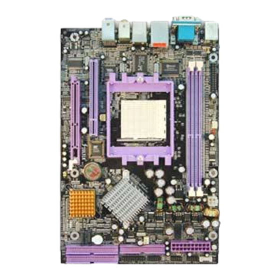
1-1 B9D-FGR Mainboard Layout ................................................9
1-2 Mainboard Specification Table ........................................... 10
1-3 Chipset System Block Diagram ............................................ 11
1-4 Mainboard Specifications and Features ............................ 12
1-4.1 CPU Socket ................................................................................... 12
1-4.2 System Chipsets ........................................................................... 12
1-4.3 Memory ......................................................................................... 12
1-4.4 BIOS ............................................................................................... 12
1-4.5 Accelerated Graphics Port (AGP) Interface ........................... 13
1-4.6 AC'97 Audio Codec on board .................................................... 13
1-4.7 Advanced System Power Management .................................... 13
1-4.8 IEEE 1394 Interface .................................................................... 13
1-4.9 Multi-I/O Functions .................................................................... 14
1-4.10 SATA / SATA RAID Interface ................................................. 14
1-4.11 Hardware Monitor on board ................................................... 14
1-4.12 Gigabit Ethernet on board ....................................................... 14
1-4.13 Form Factor ................................................................................ 14
Chapter 2 Hardware Setup ..................................... 15
2-1 CPU/CPU cooling Fan Installation on Socket 939 ........... 16
2-2 Memory Installation ............................................................. 18
2-2.1 To Install DDR SDRAM Module .............................................. 18
2-2.2 Dual Channel Memory Features ............................................... 18
2-2.3 DIMM Powered on ...................................................................... 19
2-3 AGP Slot Installation ............................................................ 19
2-4 IDE Connector Installation ................................................. 20
2-5 SATA / RAID Connectors ..................................................... 21
2-6 Floppy Drive Installation ..................................................... 22
2-7 ATX Power Supply Installation .......................................... 23
2-8 Jumper Setting ....................................................................... 24
2-8.1 How to tackle the Jumpers: ....................................................... 24
2-8.2 JKB1: Keyboard/Mouse Wake-up ............................................ 25
2-8.3 JBAT1: Clear CMOS .................................................................. 25
2-9 Other Connectors Configuration ........................................ 26
Contents
4
Contents
Advertisement
Table of Contents

Related Manuals for SOLTEK SL-B9D-FGR


Summary of Contents for SOLTEK SL-B9D-FGR
-
Page 1: Table Of Contents
SL-B9D-FGR Contents Contents Chapter 1 Specification ..........8 1-1 B9D-FGR Mainboard Layout ..........9 1-2 Mainboard Specification Table ........... 10 1-3 Chipset System Block Diagram ..........11 1-4 Mainboard Specifications and Features ......12 1-4.1 CPU Socket ................... 12 1-4.2 System Chipsets ................12 1-4.3 Memory .................. - Page 2 SL-B9D-FGR Contents 2-9.1 On-board FAN Connectors ............26 2-9.2 USB Ports and USB Pin-headers ..........27 2-9.3 Back Panel Connectors ............... 28 2-9.4 PS/2 Mouse , PS/2 Keyboard ............. 28 2-9.5 RJ45 Connector ................29 2-9.6 CD-ROM Audio Connectors (CD_In1) ........29 2-9.7 Thermal Detector .................
- Page 3 SL-B9D-FGR Contents 4-6.5 Integrated Peripherals ..............67 4-6.5.1. VIA OnChip IDE Device ............67 4-6.5.2. VIA OnChip PCI Device: ............69 4-6.5.3. Super IO Device: ............... 69 4-6.6 Power Management Setup ............71 4-6.7 PnP / PCI Configuration ............74 4-6.8 SmartDoc Anti-Burn Shield ............
- Page 4 SL-B9D-FGR Contents Memo...
-
Page 5: Chapter 1 Specification
SL-B9D-FGR Chapter 1 Specification Chapter 1 Specification Introduction This mainboard features an integration of the powerful AMD Athlon 64 939 processors and the North Bridge VIA K8T800Pro plus South Bridge VT8237, with which the whole system performance supports HyperTransport Bus up to 1GHz. -
Page 6: B9D-Fgr Mainboard Layout
SL-B9D-FGR Chapter 1 Specification 1-1 B9D-FGR Mainboard Layout Line Out Side Surround Out PS/2 COM1 IEEE Mouse 1394 RJ45 AC'97 Rear speaker COM2 PS/2 KB (underside) USB Port CDIN1 (underside) USB Port JKB1 USB Port USB Port 8110S Winbond W83687THF... -
Page 7: Mainboard Specification Table
SL-B9D-FGR Chapter 1 Specification 1-2 Mainboard Specification Table B9D-FGR Specifications and Features Socket 939 for AMD Athlon 64 939-pin CPUs North Bridge VIA K8T800Pro, supporting up to 1GHz Hyper Transport South Bridge VIA VT8237 Supporting Dual Channel DDR 400/333/266 Memory... -
Page 8: Chipset System Block Diagram
SL-B9D-FGR Chapter 1 Specification 1-3 Chipset System Block Diagram Dual Channel Socket 939 System Memory DDR 400/333/ AMD Athlon 64 266 SDRAM HyperTransport Link North Bridge AGP 8X/4X AGP Slot VIA K8T800 8x V-Link 533MB/Sec PCI Bus 1 PCI Slot... -
Page 9: Mainboard Specifications And Features
SL-B9D-FGR Chapter 1 Specification 1-4 Mainboard Specifications and Features 1-4.1 CPU Socket CPU Socket 939 on board, supporting AMD Athlon 64 processors, imple- menting up to 1GHz Hyper Transport Speed (System Bus) designed to be capable of operating up to 2000MT/s with a resulting bandwidth of up to 8 Gbytes/s and direct Memory Controller 1-4.2 System Chipsets... -
Page 10: 1-4.5 Accelerated Graphics Port (Agp) Interface
SL-B9D-FGR Chapter 1 Specification 1-4.5 Accelerated Graphics Port (AGP) Interface AGP Controller embedded on board, supporting: • 1.5V(8X/4X) power mode only, 1 AGP Slot supported • 8X 66MHz AD and SBA signaling; AGP pipelined split-transaction longburst transfers up to 2GB/sec. -
Page 11: 1-4.9 Multi-I/O Functions
• Hardware Monitor integrated in LPC I/O W83687THF, providing moni- toring functions on hardware voltage, temperatures and fan speeds. • Utility Software Soltek Hardware Monitor for displaying monitor sta- tus is enclosed in Support CD for user’s installation. 1-4.12 Gigabit Ethernet on board... -
Page 12: Chapter 2 Hardware Setup
SL-B9D-FGR Chapter 2 Hardware Setup Chapter 2 Hardware Setup To Get Things Ready for Hardware Setup ! 1. We recommend to install your CPU before any other components. For detailed installation instructions of processor, you can also refer to the pamphlet enclosed in your CPU package. -
Page 13: Cpu/Cpu Cooling Fan Installation On Socket 939
SL-B9D-FGR Chapter 2 Hardware Setup 2-1 CPU/CPU cooling Fan Installation on Socket 939 This mainboard is designed typically for barebone system in which a CPU cooling fan may also be enclosed along. If you are going to set up the 939-pin CPU into this new barebone system, you have to remove the enclosed cooling fan first. - Page 14 SL-B9D-FGR Chapter 2 Hardware Setup 7 . N o w c o n n e c t t h e P o w e r 6. Place down the cooling fan into connector to the onboard CPU Fan Base. The DIMM slot Fan connector.
-
Page 15: Memory Installation
SL-B9D-FGR Chapter 2 Hardware Setup 2-2 Memory Installation 2-2.1 To Install DDR SDRAM Module • Make sure to unplug your Power Supply before adding or removing memory module. Failure to do so may cause severe damage to both your mainboard and the memory module. -
Page 16: 2-2.3 Dimm Powered On
SL-B9D-FGR Chapter 2 Hardware Setup 2-2.3 DIMM Powered on Line Out Side Surround Out PS/2 IEEE COM1 Mouse 1394 RJ45 AC'97 • LED1 is designed on board to light Rear speaker COM2 PS/2 KB (underside) USB Port CDIN1 (underside) USB Port... -
Page 17: Ide Connector Installation
SL-B9D-FGR Chapter 2 Hardware Setup 2-4 IDE Connector Installation IDE1 and IDE2 are 2 IDE connectors supporting 4 IDE devices for up to 133MB/s data transfer. Socket 939 IDE2 IDE1 SATA1 SATA2 Pin 1 (to Red Line of IDE cable) -
Page 18: Sata / Raid Connectors
SL-B9D-FGR Chapter 2 Hardware Setup 2-5 SATA / RAID Connectors 2 Serial ATA connectors for 2 SATA Hard Disks with RAID mode are supported by the South Bridge VIA VT8237. Please see Chapter 5 Disk Array Installation for detail RAID installaion. -
Page 19: Floppy Drive Installation
SL-B9D-FGR Chapter 2 Hardware Setup 2-6 Floppy Drive Installation To install FDC on barebone system, you should connect the end with Signal Swap of the floppy drive cable to floppy drive, and connect the other end to the floppy drive connector (FDC) on Mainboard. -
Page 20: Atx Power Supply Installation
SL-B9D-FGR Chapter 2 Hardware Setup 2-7 ATX Power Supply Installation Dual-Channel DDR 400/333/266/200 MHz DIMM1 DIMM2 Main Power Connector +12V Power Connector +12V PWR OK +12V +12V PS ON# +3.3V -12V +3.3V +3.3V Pin1 Pin11 ATX V2.03 Power Supply is strongly recommended for mainboard run- ning with this mainboard. -
Page 21: Jumper Setting
SL-B9D-FGR Chapter 2 Hardware Setup 2-8 Jumper Setting 2-8.1 How to tackle the Jumpers: A 2-pin Jumper A 3-pin Jumper If a pin-header (of 2 or more pins) is designed in such a way that its pins can be closed or linked together to... -
Page 22: 2-8.2 Jkb1: Keyboard/Mouse Wake-Up
SL-B9D-FGR Chapter 2 Hardware Setup The following diagrams show the locations and settings of jumpers on the mainboard. 2-8.2 JKB1: Keyboard/Mouse Wake-up JKB1 is designed to enable / disable the PS/2 Keyboard or PS/2 Mouse Wake-up (from suspend mode). Setting JKB1 to... -
Page 23: Other Connectors Configuration
SL-B9D-FGR Chapter 2 Hardware Setup 2-9 Other Connectors Configuration This section lists out all connectors configurations for users’ reference. 2-9.1 On-board FAN Connectors Line Out Void Side Surround Out PS/2 IEEE COM1 Mouse 1394 RJ45 Sensor AC'97 Rear speaker COM2... -
Page 24: 2-9.2 Usb Ports And Usb Pin-Headers
SL-B9D-FGR Chapter 2 Hardware Setup 2-9.2 USB Ports and USB Pin-headers This series provides 4 USB ports on board supporting various USB devices. In addition, 2 USB pin-headers are added on board to provide expansion of 4 more optional USB ports by using 2 additional USB Cables. -
Page 25: 2-9.3 Back Panel Connectors
SL-B9D-FGR Chapter 2 Hardware Setup 2-9.3 Back Panel Connectors G : PS/2 Keyboard A : PS/2 Mouse H : COM2 B : COM1 : 2 USB ports C : RJ45 J : 2 USB ports D : IEEE 1394A K : Rear Speaker-out... -
Page 26: 2-9.5 Rj45 Connector
SL-B9D-FGR Chapter 2 Hardware Setup 2-9.5 RJ45 Connector One RJ45 connector is on board for LAN connection, supporting 10/ 100/1000Mb data transfer. Orange LED blinks to indicate Yellow LED “On” to indicate that data transmission is Network hub is in connection undergoing in 1000 Base T with the system. -
Page 27: 2-9.7 Thermal Detector
SL-B9D-FGR Chapter 2 Hardware Setup 2-9.7 Thermal Detector Line Out Side Surround Out PS/2 IEEE COM1 Mouse 1394 RJ45 AC'97 Rear speaker COM2 PS/2 KB (underside) USB Port CDIN1 (underside) USB Port JKB1 USB Port USB Port 8110S Winbond W83687THF... -
Page 28: 2-9.9 Complex Pin-Header (Front Panel Connectors)
SL-B9D-FGR Chapter 2 Hardware Setup 2-9.9 Complex Pin-header (Front Panel Connectors) This complex Pin-header consists of the following connectors for vari- ous front panel supports. When you have fixed the mainboard to the case, join the connectors of this Complex Pin-header to the case Front Panel. -
Page 29: 2-9.10 Ieee 1394A Port/Pin-Header
SL-B9D-FGR Chapter 2 Hardware Setup 2-9.10 IEEE 1394a Port/Pin-header 1394A Interface, with VT6307 Open Host Controller on board, support- ing 2 x 1394A serial ports: • Each 1394A port supporting 400/200/100 Mbits transfer rate. 1394A port Line Out Connect 1394A... -
Page 30: 2-9.11 Printer Port: Lpt1
SL-B9D-FGR Chapter 2 Hardware Setup 2-9.11 Printer Port: LPT1 LPT1 is a parallel printer port. Line Out Side Surround Out PS/2 COM1 IEEE 1394 Mouse RJ45 LPT1: Printer Port AC'97 Rear speaker COM2 PS/2 KB (underside) USB Port CDIN1 (underside) -
Page 31: Chapter 3 Software Setup
SL-B9D-FGR Chapter 3 Software Setup Chapter 3 Software Setup Drivers, Utilities and Software Installation Support CD: This mainboard will be shipped with a Support CD which contains those necessary driver files, Application Softwares and some helpful utilities. It is a user-friendly, auto-run CD which will open itself up in a CD-ROM automatically. -
Page 32: To Open Up Support Cd
SL-B9D-FGR Chapter 3 Software Setup 3-1 To Open Up Support CD: 1. Please put the Support CD enclosed in your mainboard package into the CD-ROM drive. In a few seconds, the Main Menu will automatically appear, displaying the contents to be installed for this... -
Page 33: Via 4-In-1 Drivers Installation
SL-B9D-FGR Chapter 3 Software Setup 3-2 VIA 4-IN-1 Drivers Installation 1. Following the procedures of opening the Support CD, click to “ VIA 4- in-1 Drivers” to proceed. 3. “VIA Service Pack README” 2 . T h e V I A S e r v i c e P a c k... - Page 34 SL-B9D-FGR Chapter 3 Software Setup 6. Select “Install VIA PCI IDE 7. Select “Install VIA AGP Driver” Driver” checkbox, then click the in turbo mode and press “Next” “Next” button to continue. button to continue. Next Next 8. After all these setup procedures have finished, you should restart your computer by clicking on “OK”...
-
Page 35: Directx 9 Installation
SL-B9D-FGR Chapter 3 Software Setup 3-3 DirectX 9 Installation DirectX 9 supports operating systems Windows 98SE/ME/2000/XP for a better 3D display. Whenever the OS is not integrated with DirectX 9, DirectX 9 installation is recommended. 1. Following the procedures of opening the Support CD, click on the Main Menu “DirectX9”... - Page 36 SL-B9D-FGR Chapter 3 Software Setup 3. Instantly, next screen DirectX 9.0 Runtime Install screen will pop up to prompt you to continue. Click “Next” button to continue. Next 4. The Setup Program will then guide you through the whole driver setup until the “Restart Computer”...
-
Page 37: Ac'97 Audio Driver Installation
SL-B9D-FGR Chapter 3 Software Setup 3-4 AC’97 Audio Driver Installation RTL ALC850 8-channel AC97 Audio Codec on board, AC’97 2.3 compat- ible stereo audio code for PC multimedia systems. AC’97 Audio Codec Driver is provided in Support CD for user’s installation. -
Page 38: 3-4.2 Verifying 8-Channel Audio
SL-B9D-FGR Chapter 3 Software Setup 3-4.2 Verifying 8-channel Audio After installation of AC’97 8-channel Codec, you must configure the 7.1 Speaker connection to enable the 8-channel audio. 1. Connect your on-board Audio Connector to your 8-channel speakers as depicted in the figure below:... - Page 39 SL-B9D-FGR Chapter 3 Software Setup 3. The AC’97 Audio Configuration” screen will pop out. Clikc the “Speaker Configuration” bar with your mouse. 4. Instantly, the “Speaker Configuration” screen will pop out. Pick the items “8-channelSpeaker” and then click on the Auto Test button.
-
Page 40: To Install Rtl8110S Gigabit Ethernet Drivers
SL-B9D-FGR Chapter 3 Software Setup 3-5 To Install RTL8110S Gigabit Ethernet Drivers RTL8110S Gigabit LAN driver for Windows 98/ME / 2000 / XP. After restarting system, click on the Onboard Giga LAN Driver to start setup. 1. Instantly, the InstallShield Wizard pop out. -
Page 41: Usb 2.0 Driver Installation
SL-B9D-FGR Chapter 3 Software Setup 3-6 USB 2.0 Driver installation VIA USB V2.0 is already integrated on board. Its 480Mb/s transfer rate supports operating systems Windows 98SE/ME/2000/XP. USB2.0 Driver is typically for Windows 98SE/ME. For Windows 2000/XP, users can install their latest Service Pack instead of the USB2.0 driver to gain the USB2.0 support. - Page 42 SL-B9D-FGR Chapter 3 Software Setup 3. Instantly, next screen will pop up to prompt you to select component. Select “Install USB Driver” and click “Next” button to continue. Next 4. The USB 2.0 Setup Program will then guide you through the whole driver setup until the “Finish”...
-
Page 43: Install Hardware Monitor Utility
SL-B9D-FGR Chapter 3 Software Setup 3-7 Install Hardware Monitor Utility 3-7.1 Installation Hardware Monitor is built on this mainboard. Its installation is pro- grammed to a fully automated mode on Windows 9X/Me/NT4/2000/ XP. Users can follow the model installation below for its installation on various Windows System. -
Page 44: 3-7.2 Verification
SL-B9D-FGR Chapter 3 Software Setup 3-7.2 Verification 1. After installing Soltek Hardware Monitor, double click “SoltekHM” icon on the desktop to open the main window of the Soltek Hardware Doctor. 2.Then the pop-up screen will show all information about CPU Temperature, Fan Speed and various Voltages. -
Page 45: Install Amd 64 Cpu Quiet Driver
SL-B9D-FGR Chapter 3 Software Setup 3-9 Install AMD 64 CPU Quiet Driver AMD 64 CPU Cool and Quiet Driver is provided in Support CD for im- proving AMD 64 CPU performance in Windows XP system. 1.Click on the Main Menu of the Support CD “AMD Cool ‘N’ Quiet Driver”... - Page 46 SL-B9D-FGR Chapter 3 Software Setup 5. Read the Known Limitations information and click Next button to continue. 6. Click Next button to continue. 7. In a few seconds, setup completes. Select Restart system now and click Finish button to restart system and complete setup.
-
Page 47: Chapter 4 Bios Setup
SL-B9D-FGR Chapter 4 BIOS Setup Chapter 4 BIOS Setup THE BIOS BIOS stands for Basic Input and Output System. It was once called ROM BIOS when it was stored in a Read-Only Memory(ROM) chip Now manufacturers would like to store BIOS in EEPROM which means Electrically Erasable Programmable Memory. -
Page 48: About Bios Setup
SL-B9D-FGR Chapter 4 BIOS Setup 4-1 About BIOS Setup BIOS setup is an interactive BIOS program that you need to run when: 1. Changing the hardware of your system. (For example: installing a new Hard Disk etc.) 2. Modifying the behavior of your computer. (For example: changing the system time or date, or turning special features on or off etc.) -
Page 49: To Upgrade Bios
SL-B9D-FGR Chapter 4 BIOS Setup 4-5 To Upgrade BIOS • System BIOS is incorporated into a Flash memory component. Flash BIOS allows user to upgrade BIOS without the need to replace an EPROM component. • The Upgrade Utility can be loaded on a floppy diskette to execute saving, verifying, and updating the system BIOS. - Page 50 SL-B9D-FGR Chapter 4 BIOS Setup Step 4. Type awdflash *.bin /sn/py/cc and then press <Enter> to run BIOS upgrade program. (*.bin depends on your mainboard model and version code. Instead of typing “*”, you should type specific file name for your specific mainboard).
- Page 51 SL-B9D-FGR Chapter 4 BIOS Setup BIOS Update Illustration: (Taking K8AV2008.bin as a BIOS file example) (1) Executing the “awdflash.exe k8AV2008.bin” in DOS system, Award Flash Memory Writer Start Screen appears: To input BIOS file name. AwardBIOS Flash Utility V8.24F (C)Phoenix Technologies Ltd. All Rights Reserved...
- Page 52 SL-B9D-FGR Chapter 4 BIOS Setup (4) Updating is in progress. Do not turn off power at this moment. AwardBIOS Flash Utility V8.24F (C)Phoenix Technologies Ltd. All Rights Reserved For K8T800-8237-6A7L0SAAC-00 Date: 09/18/2003 Flash Type - SST 39SF020 /5V File Name to Program : k8av2008.bin...
-
Page 53: Bios Setup
SL-B9D-FGR Chapter 4 BIOS Setup 4-6 BIOS SETUP --- CMOS Setup Utility Warning and Tips: If changing CMOS Configuration causes difficulty in rebooting system, you can take the following measures: 1. At pressing the power button to reboot, press the “Insert” key at the same time. - Page 54 SL-B9D-FGR Chapter 4 BIOS Setup 3. When one main item of the Main Menu is chosen and clicked on, its submenu will appear to display the related items and options. On the other hand, a list of operation guide will appear at the end of the...
-
Page 55: 4-6.2 Standard Cmos Setup
SL-B9D-FGR Chapter 4 BIOS Setup 4-6.2 Standard CMOS Setup Standard CMOS Setup records some basic system hardware configuration and sets the system clock and error handling. You only need to modify the configuration values of this option if you want to change your system hardware configuration or when the data stored in the CMOS memory gets lost or damaged. - Page 56 SL-B9D-FGR Chapter 4 BIOS Setup Date (mm:dd:yy) The BIOS determines the day of the week from the other date information. This field is for information only. Press the left or right arrow key to move to the desired field (date, month, year). Press the PgUp or PgDn key to increment the setting, or type the desired value into the field.
- Page 57 SL-B9D-FGR Chapter 4 BIOS Setup Drive A Select this field to the type(s) of floppy disk drive(s) installed in your system. The choices are: 360KB, 5.25 in. 1.2MB, 5.25 in. 720KB, 3.5 in. 1.44MB, 3.5 in. 2.88MB, 3.5 in. None Video Select the type of primary video subsystem in your computer.
-
Page 58: 4-6.3 Advanced Bios Features
SL-B9D-FGR Chapter 4 BIOS Setup 4-6.3 Advanced BIOS Features Advanced BIOS Features improves your system performance or sets up system features according to your preference. Run the Advanced BIOS Features as follows: Choose “Advanced BIOS Features” from the Main Menu and a screen... - Page 59 SL-B9D-FGR Chapter 4 BIOS Setup Hard Disk Boot Priority This item allows you to decide the priority of Boot- able Hard Disks. Press enter to get into the submenu to choose the prior bootable Hard Disk. Virus Warning When enabled, you receive a warning message if a...
- Page 60 SL-B9D-FGR Chapter 4 BIOS Setup Boot Up Floppy Seek When enabled, the BIOS tests (seeks) floppy drives to determine whether they have 40 or 80 tracks. Only 360-KB floppy drives have 40 tracks; drives with 270KB, 1.2MB, and 1.44MB capacity all have 80 tracks.
-
Page 61: 4-6.4 Advanced Chipset Features
SL-B9D-FGR Chapter 4 BIOS Setup 4-6.4 Advanced Chipset Features Advanced Chipset Features is used to modify the values of chipset buffers. These buffers control the system options. Run the Advanced Chipset Features as follows: Choose “Advanced Chipset Features” from the Main Menu and a... - Page 62 SL-B9D-FGR Chapter 4 BIOS Setup AGP & P2P Bridge Control: To press< Enter > on AGP & P2P Bridge will reveal the following item. AGP Aperture Size Options: 32; 64; 128; 256M; 512M; 1G. Memory mapped and graphics data structures can reside in a Graphics Aperture.
- Page 63 SL-B9D-FGR Chapter 4 BIOS Setup LDT & PCI Bus Control: To press< Enter > on LDT & PCI Bus Control will reveal the following item(s). Upstream LDT Bus To set Upstream LDT BUS Width. Width Choices: 8 bit; 16 bit Downstream LDT Bus To set Downstream LDT BUS Width.
-
Page 64: 4-6.5 Integrated Peripherals
SL-B9D-FGR Chapter 4 BIOS Setup 4-6.5 Integrated Peripherals Integrated Peripherals option allows you to get some information inside your system when it is working. Run the Integrated Peripherals as follows: Choose “Integrated peripherals” from the Main Menu and a list of options... - Page 65 SL-B9D-FGR Chapter 4 BIOS Setup VIA OnChip IDE Device: To press< Enter > on VIA OnChip IDE Device will reveal the following item(s). OnChip SATA To enable/disable the onchip SATA controller. SATA Mode To select the IDE or RAID mode for the SATA connectors on board.
-
Page 66: 4-6.5.2. Via Onchip Pci Device
SL-B9D-FGR Chapter 4 BIOS Setup 4-6.5.2. VIA OnChip PCI Device: To press< Enter > on VIA OnChip PCI Device will reveal the following item(s). Item Help VIA-3058 AC97 Audio Enabled OnChip USB Controller All Enabled OnChip EHCI Controller Enabled USB Emulation... - Page 67 SL-B9D-FGR Chapter 4 BIOS Setup Onboard Serial Select an address and corresponding interrupt Port 1 / Port 2 for the first/second serial port. Choices: Disabled; Auto; 3F8/IRQ4; 2F8/IRQ3; 3E8/IRQ4; 2E8/IRQ3 UART Mode Select The serial port on your system may offer a vari- ety of infrared port modes.
-
Page 68: 4-6.6 Power Management Setup
SL-B9D-FGR Chapter 4 BIOS Setup 4-6.6 Power Management Setup Power Management Setup allows you to set the system’s power saving functions. Run the Power Management Setup as follows: Choose “Power Management Setup” from the Main Menu and a list of... - Page 69 SL-B9D-FGR Chapter 4 BIOS Setup HDD Power Down When enabled after the set time of system inactivity, the hard disk drive will be powered down while all other devices remain active. Suspend Mode When enabled after the set time of system inactivity, the whole system will be suspended.
- Page 70 SL-B9D-FGR Chapter 4 BIOS Setup IRQ/Event Activity Detect: To press< Enter > on IRQ/Event Activity Detect will reveal following items. PS2KB Wakeup Select To select the PS/2 KB Wake-up mode. Choices: Hot key; Password PS2KB/Ms Wakeup To set the hot key to wake up the system by PS/2 from S3/S4/S5 KB/Ms from S3/S4/S5.
-
Page 71: 4-6.7 Pnp / Pci Configuration
SL-B9D-FGR Chapter 4 BIOS Setup 4-6.7 PnP / PCI Configuration PnP/PCI Configuration allows you to modify the system’s power saving functions. Run the PnP/PCI Configuration as follows: Choose “PnP/PCI Configuration” from the Main Menu and a screen with a list of options will appear:... - Page 72 SL-B9D-FGR Chapter 4 BIOS Setup PNP OS Installed Allows you to configure the PNP devices by BIOS or O/S. Choices: No(by BIOS); Yes(by O/S) Reset Configuration Normally, you leave this Disabled(default). Select Data Enabled to reset Extended System Configuration Data (ESCD), when you exit Setup if you have in-...
-
Page 73: 4-6.8 Smartdoc Anti-Burn Shield
SL-B9D-FGR Chapter 4 BIOS Setup 4-6.8 SmartDoc Anti-Burn Shield This section helps you to get more information about your system in- cluding CPU temperature, FAN speed and voltage. Choose “SmartDoc Anti-Burn Shield” from the Main Menu and a screen with a list of options will appear:... -
Page 74: 4-6.9 Frequency/Voltage Control
SL-B9D-FGR Chapter 4 BIOS Setup 4-6.9 Frequency/Voltage Control Choose “Frequency/Voltage Control” from the Main Menu and a screen with a list of options will appear: Phoenix - AwardBIOS CMOS Setup Utility Frequency/Voltage Control Item Help CPU Ratio StartUp Auto Detect PCI Clk... -
Page 75: 4-6.10 Load Optimized Defaults
SL-B9D-FGR Chapter 4 BIOS Setup 4-6.10 Load Optimized Defaults When you press <Enter> on this item, you will get a confirmation dialog box with a message similar to: “ Load Optimized Defaults (Y / N) ? N ” Phoenix - AwardBIOS CMOS Setup Utility... -
Page 76: 4-6.12 Save & Exit Setup
SL-B9D-FGR Chapter 4 BIOS Setup 2. The first time you run this option, enter your password up to 8 char- acters and press <Enter>. (The screen does not display the entered characters.) 3. After you enter the password, the following message appears prompt- ing you to confirm the password: “Confirm Password :... -
Page 77: Chapter 5 Vt8237 Sata Raid
SL-B9D-FGR Chapter 5 VIA VT8237 RAID Setup Chapter 5 VT8237 SATA RAID THE VIA SATA RAID Controller VT8237 & RAID Driver VIA RAID (Redundant Array of Independent Disks) Controller is built in the South Bridge VT8237. With this RAID Controller, the VIA SATA RAID BIOS is built into the system to help configure the Redundant Disk Array. -
Page 78: About Disk Array
SL-B9D-FGR Chapter 5 VIA VT8237 RAID Setup 5-0 About Disk Array 5-0-1 Disk Array Interpretation A “Disk Array” is formed from a group of 2 disk drives with the RAID (Redundent Array of Independent Disks) technology. The aim of a Disk Array is to provide better perfornance and/or data fault tolerance. -
Page 79: First Step To Set Up Sata Raid System
SL-B9D-FGR Chapter 5 VIA VT8237 RAID Setup 5-1 First Step to Set Up SATA RAID System 2 Serial ATA connectors for 2 SATA Hard Disks with RAID mode are supported by the South Bridge VIA VT8237. Socket 939 PCI1 SATA1... -
Page 80: Enable Sata-Raid Interface With System Bios
SL-B9D-FGR Chapter 5 VIA VT8237 RAID Setup 5-2 Enable SATA-RAID Interface with System BIOS (1) Boot system and watch for the following initial screen to appear: VIA Technologies, Inc. VIA VT6420 RAID BIOS Setting Utility v (xxx) Copyright (C) VIA Technologies, Inc. All right reserved. -
Page 81: To Enter Via Tech. Raid Bios Setup
SL-B9D-FGR Chapter 5 VIA VT8237 RAID Setup 5-3 To Enter VIA Tech. RAID BIOS Setup Reboot the system with “OnChip SATA” enabled in system BIOS Setup and watch for the following initial screen to appear: VIA Technologies, Inc. VIA VT8237 Serial RAID BIOS Setting Utility V2.10 Copyright (C) VIA Technologies, Inc. -
Page 82: Using Via Raid Bios Setup To Create Disk Array
SL-B9D-FGR Chapter 5 VIA VT8237 RAID Setup 5-4 Using VIA RAID BIOS Setup to Create Disk Array (5-4-1) When you press <Enter> on the “Create Array” bar, the follow- ing screen shows up. Press <Enter>on this bar to select the RAID mode. - Page 83 SL-B9D-FGR Chapter 5 VIA VT8237 RAID Setup (5-4-3) The following screen shows that RAID 0 (Striping) is selected. Now, use the “Arrow” key to mark up the “Auto Setup For Performance” bar. VIA Tech. VT8237 SATA RAID BIOS Ver 2.10...
- Page 84 SL-B9D-FGR Chapter 5 VIA VT8237 RAID Setup (5-4-5) Instantly, the RAID 0 Striping mode is set up and shown on the screen. Then press <Escape> key to exit the screen. VIA Tech. VT8237 SATA RAID BIOS Ver 2.10 Set/Clear bootable array...
- Page 85 SL-B9D-FGR Chapter 5 VIA VT8237 RAID Setup (5-4-7) Instantly, the Master Hard Disk is marked up. Press <Enter> on the screen to set up the “Boot Disk”. VIA Tech. VT8237 SATA RAID BIOS Ver 2.10 Set/Clear bootable array Create Array...
-
Page 86: Using Via Raid Bios Setup To Change Array Mode
SL-B9D-FGR Chapter 5 VIA VT8237 RAID Setup 5-5 Using VIA RAID BIOS Setup to change Array mode (5-5-1) If you wants to change the RAID mode, say, from RAID 0 to RAID 1, you must return to the Initial RAID BIOS Setup screen. Then, press the “Arrow”... - Page 87 SL-B9D-FGR Chapter 5 VIA VT8237 RAID Setup (5-5-3) When the message “The selected array will be destroied..” appears on screen, press <Y> key to continue. VIA Tech. VT8237 SATA RAID BIOS Ver 2.10 Delete a RAID array contain the Create Array...
-
Page 88: To Install Sata Raid Driver
SL-B9D-FGR Chapter 5 VIA VT8237 RAID Setup 5-6 To Install SATA RAID Driver RAID Driver is incorporated in Support CD/Floppy Disk for user’s installation. The Driver Floppy Disk is needed for SATA RAID installa- tion on Windows 2K/XP. If you cannot find this Driver Floppy Disk in the mainboard package, you can make one by copying the driver from the Driver CD into a Floppy Disk. -
Page 89: To Install Sata Raid Driver On Windows 98Se/Me
SL-B9D-FGR Chapter 5 VIA VT8237 RAID Setup 5-6-2 To Install SATA RAID Driver on Windows 98SE/ME (1) Get ready the Floppy Diskette holding the SATA RAID Driver. (2) Check that SATA Hard Disks are connected properly to the SATA Connectors. - Page 90 SL-B9D-FGR Chapter 5 VIA VT8237 RAID Setup (11) In the “Update device Driver Wizard” screen, click “Next” to continue until you see a dialog box asking you to “Specify a location” for the driver. You should now insert the SATARAID Driver CD/Diskette into CD-ROM/Drive A.
Need help?
Do you have a question about the SL-B9D-FGR and is the answer not in the manual?
Questions and answers