Table of Contents
Advertisement
Quick Links
B7A-F
ITEM CHECKUP ....................................................................8
Chapter 1 Specification ............................................. 9
1-1 B7A-F Layout ......................................................................... 10
1-2 Mainboard Specifications ..................................................... 11
1-2.1 CPU Socket ................................................................................... 11
1-2.2 System Chipsets ........................................................................... 11
1-2.3 Memory ......................................................................................... 11
1-2.4 BIOS ............................................................................................... 11
1-2.5 Integrated GeForce4 MX GPU ................................................. 12
1-2.6 AGP Interface ............................................................................... 12
1-2.7 Advanced System Power Management .................................... 12
1-2.8 Multi-I/O Functions .................................................................... 12
1-2.9 Expansion Slots ............................................................................ 13
1-2.10 Integrated APU and AC'97 Audio Codec on board ............ 13
1-2.11 Hardware Monitor on board ................................................... 13
1-2.12 IEEE 1394A OHCI Controller on board ............................... 13
1-2.13 LAN Controller on board ......................................................... 13
1-2.14 Front Panel Audio-out Connector .......................................... 13
1-2.15 Form Factor ................................................................................ 13
1-3 Mainboard Specification Table ........................................... 14
1-4 Chipset System Block Diagram ........................................... 15
Chapter 2 Hardware Setup ..................................... 16
2-1 CPU Identification and Installation ................................... 17
2-1.1 CPU Identification Legends ....................................................... 17
2-1.2 CPU Installation with Socket 462 ............................................. 18
2-2 Memory Installation ............................................................. 19
2-2.1 To Install DDR SDRAM Module .............................................. 19
Contents
4
Advertisement
Table of Contents

Related Manuals for SOLTEK B7A-F


Summary of Contents for SOLTEK B7A-F
-
Page 1: Table Of Contents
B7A-F Contents ITEM CHECKUP ..............8 Chapter 1 Specification ..........9 1-1 B7A-F Layout ................. 10 1-2 Mainboard Specifications ............. 11 1-2.1 CPU Socket ................... 11 1-2.2 System Chipsets ................11 1-2.3 Memory ..................11 1-2.4 BIOS ....................11 1-2.5 Integrated GeForce4 MX GPU ..........12 1-2.6 AGP Interface ................ - Page 2 Contents 2-2.2 Dual-channel DDR DIMM configuration ........ 20 2-2.3 To Remove a DIMM ..............20 2-3 VGA / AGP Slot Installation ..........21 2-4 IDE Connector Installation ..........22 2-5 Floppy Drive Connector Installation ......... 23 2-6 ATX Power Supply Installation .......... 24 2-7 Jumper Settings ..............
- Page 3 B7A-F Chapter 3 Software Setup ........42 3-1 To Open up the Support CD ..........43 3-2 To Install “nVIDIA nForce2 All-in-1 Driver” ....44 3-3 To Verify 6-channel Audio Configuration ......46 3-3.1 To verify 6-channel Audio on Volume Control ....... 46 3-3.2 To verify 6-channel Audio on nForce Control Panel .....
- Page 4 Contents 4-6.9 CPU Ratio/Voltage Control ............83 4-6.10 Load Optimized Defaults ............85 4-6.11 SET SUPERVISOR / USER PASSWORD ......86 4-6.12 SAVE & EXIT SETUP .............. 87 4-6.13 EXIT WITHOUT SAVING ............87 APPENDICES ............88 Appendix-1 Identify BIOS Version & BIOS Part Number ... 89 Appendix-2 Identify Mainboard Model Number ....
-
Page 5: Item Checkup
B7A-F ITEM CHECKUP • Mainboard • User Manual (Mainboard) • Multi-lingual Quick Installation Guide • Support CD • Bundled Bonus Pack CD • Bundled Bonus Pack Manual • Cables ATA 100 IDE Cable (one connector at each end) ATA 66 IDE Cable (two connectors at one end) -
Page 6: Chapter 1 Specification
Chapter 1 Specification Chapter 1 Specification Introduction This mainboard features an integration of the powerful AMD proces- sors Athlon/Athlon XP/Duron and the North Bridge nVIDIA nFORCE2 IGP plus South Bridge nFORCE2 MCP-T, with which the whole system performance supports 400/333/266/200MHz system bus. nVIDIA nFORCE2 IGP plus nFORCE2 MCP-T supports on-board AMD processors to implement the 400/333/266/200 MHz Front Side Bus, the AGP 8X/4X interface, the integrated GeForce4 MX Graphics port, the... -
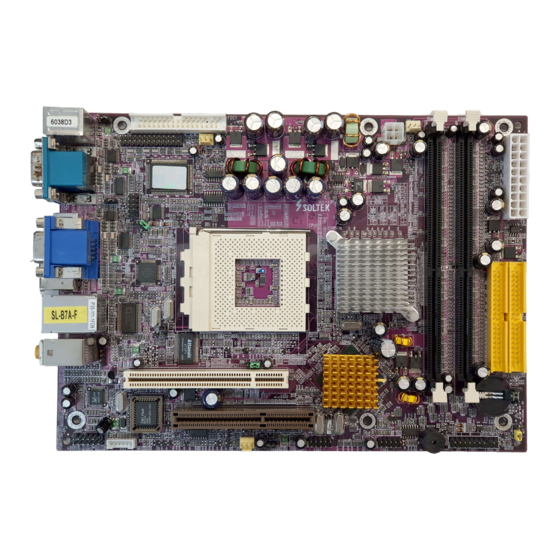
Page 7: B7A-F Layout
B7A-F 1-1 B7A-F Layout Printer Port (optional) COM2 Port (optional) AC'97 Codec ALC650 JKB1 COM2 ICS 1893 FW803 JCLK1 1394A LPC I/O W83627HF Fan1 FDC1 Fan2 JCLK2 JUSB1 USB3 +12V Power USB2 Fan3 DDR 333/266 MHz DIMM2 DIMM1 IDE2 Battery... -
Page 8: Mainboard Specifications
Chapter 1 Specification 1-2 Mainboard Specifications 1-2.1 CPU Socket CPU Socket 462 (Socket A) on board, supporting AMD Athlon, Athlon XP and Duron processors and implementing 400/333/266/200MHz sys- tem bus 1-2.2 System Chipsets North Bridge nVIDIA nFORCE2 IGP: • Managing and supporting 400/333/266/200MHz system Bus, AGP 8X/4X interface, integrated GeForce4 MX graphics accelerator and DDR 333/266MHz Memory Interface South Bridge nVIDIA nFORCE2 MCP-T... -
Page 9: 1-2.5 Integrated Geforce4 Mx Gpu
B7A-F 1-2.5 Integrated GeForce4 MX GPU GeForce4 MX GPU is embedded on board, supporting: • 256-bit 3D and 2D graphics accelerator • nView Dual-Display architecture supporting any combination of desk- top VGA monitors and TV sets • Integrated NTSC/PAL TV Encoder supporting resolutions up to 1024x768 •... -
Page 10: 1-2.9 Expansion Slots
• Hardware Monitor supported by LPC I/O W83627HF, providing moni- toring functions on hardware voltage, temperatures and fan speeds. • Utility Software Soltek Hardware Monitor for displaying monitor sta- tus is enclosed in Support CD for user’s installation. 1-2.12 IEEE 1394A OHCI Controller on board IEEE 1394A OHCI Controller integrated in nFORCE2 MCP-T •... -
Page 11: Mainboard Specification Table
B7A-F 1-3 Mainboard Specification Table SL-B7A-F Specifications and Features Socket 462 for AMD Athlon, Athlon XP, Duron CPU North Bridge nFORCE2 IGP, 400/333/266/200MHz FSB South Bridge nFORCE2 MCP-T BIOS Award BIOS Dual Channel DDR 333/266 SDRAM, up to 2GB in... -
Page 12: Chipset System Block Diagram
Chapter 1 Specification 1-4 Chipset System Block Diagram Socket 462 for AMD CPUs System Bus 400/333/266/200MHz 2 VGA Connectors Dual Channel DDR memory Interface North Bridge Interface System nVIDIA Memory TV Out DDR 333/ nFORCE2 266 SDRAM AGP 8X/4X AGP Slot HyperTransport IEEE 1394 ports PCI Slot... -
Page 13: Chapter 2 Hardware Setup
B7A-F Chapter 2 Hardware Setup To Get Things Ready for Hardware Setup ! 1. We recommend to install your CPU before any other components. For detailed installation instructions of processor, you can also refer to the pamphlet enclosed in your CPU package. -
Page 14: Cpu Identification And Installation
Chapter 2 Hardware Setup 2-1 CPU Identification and Installation 2-1.1 CPU Identification Legends XXXXXXXXXXX XXXXXXXXXXXX XXXXXXX XXXXXXXXX XXXXXXXXXXX XXXX 0.13 um CPU 0.18um CPU AMD Athlon(Duron) AX 1900 D U T 3 C (1) (2) (3) (4) (5) (6) (7) Family / Architecture: A, AX, AXDA=AMD Athlon Processor D, DHD, DHM, DHL=AMD Duron Processor... -
Page 15: 2-1.2 Cpu Installation With Socket 462
B7A-F 2-1.2 CPU Installation with Socket 462 This mainboard is built with CPU Socket 462 supporting the AMD CPUs Athlon, Athlon XP and Duron: • Follow the steps described in this section to install CPU into the on- board Socket 462. -
Page 16: Memory Installation
Chapter 2 Hardware Setup 2-2 Memory Installation How to tackle the memory Modules: • Make sure to unplug your power supply before adding or removing memory module. Failure to do so may cause severe damage to both your mainboard and the memory module. •... -
Page 17: 2-2.2 Dual-Channel Ddr Dimm Configuration
B7A-F 2-2.2 Dual-channel DDR DIMM configuration 1. To enabl Dual-channel function on this mainboard, Both DIMM1 and DIMM2 must be populated with a DDR DIMM module of the same ca- pacity and Band width (frequency). 2. If Dual-channel configuration is set up, nFORCE2 dual memory con- troller can double the DDR memory bandwidth up to 5.4GB/s with... -
Page 18: Vga / Agp Slot Installation
Chapter 2 Hardware Setup 2-3 VGA / AGP Slot Installation 1. To install onboard VGA, please connect your monitor directly to either or both VGA connectors on board. The onboard VGA connectors support simultaneous Dual Display. On the other hand, VGA1 is the Master VGA channel for VGA connection, but VGA2 is the second VGA channel for VGA/S-Video select.(For the second VGA/S-Video select, please refer to Jumper Jp2 set-up.) -
Page 19: Ide Connector Installation
B7A-F 2-4 IDE Connector Installation To install IDE Connector, you may connect the blue connector of IDE cable to the primary (IDE1) or secondary (IDE2) connector on board, and then connect the gray connector to your slave device and the black connector to your master device. -
Page 20: Floppy Drive Connector Installation
Chapter 2 Hardware Setup 2-5 Floppy Drive Connector Installation To install FDC, you should connect the end of FDC cable with single connector to the board, and connect the other end with two connectors to the floppy drives. Pin 1 (to Red Line) AC'97 Codec ALC650... -
Page 21: Atx Power Supply Installation
B7A-F 2-6 ATX Power Supply Installation +12V Power Connector +12V AC'97 Codec ALC650 JKB1 COM2 ICS 1893 FW803 JCLK1 1394A LPC I/O W83627HF +12V Fan1 +12V FDC1 Fan2 JCLK2 PWR OK JUSB1 USB3 PS ON# +12V Power USB2 Fan3 DIMM2 DDR 333/266 MHz +3.3V... -
Page 22: Jumper Settings
Chapter 2 Hardware Setup 2-7 Jumper Settings The following diagrams show the locations and settings of jumper blocks on the mainboard. Jp2: JKB1: 2nd VGA/TV-Out Select PS/2 KB/Mouse Power On/Wake Up 1-2 closed 1-2 closed TV Out Enabled PS/2 KB/Mouse Power On / (2nd VGA Disabled) Wake Up Disabled (default) -
Page 23: 2-7.1 How To Tackle The Jumpers
B7A-F 2-7.1 How to tackle the Jumpers: A 2-pin Jumper A 3-pin Jumper If a pin-header (of 2 or more pins) is designed in such a way that its pins can be closed or linked together to The conductor inside the cap set up a specific function, this header links two header-pins together. -
Page 24: 2-7.3 Jclk1: Cpu & Str(S3) Support
Chapter 2 Hardware Setup 2-7.3 JCLK1: CPU Clock Adjustable 1. Setting JCLK1 all pins open is for JCLK1: adjusting CPU clock by BIOS setup after CPU Clock Adjustable booting system. If overclocking by BIOS setup fails, the system will automatically (default) All pins open reboot with default CPU clock 100MHz. -
Page 25: 2-7.4 Jbat1: Nvidia Clear Cmos
B7A-F nVIDIA Boot-Failure-Reboot Procedures: Whenever nVIDIA system fails to boot (including overclock and non- overclock cases), it requires a more guaranteed Reboot Procedure to restart system. (1) To reboot nVIDIA system, users should first power off the system. (2) If a “CPU Clock Select” Jumper is on board, restore this jumper setting to default setting. -
Page 26: 2-7.5 Jp3: Anti-Burn Shield (Absii)
Chapter 2 Hardware Setup 2-7.5 Jp3: Anti-burn Shield (ABSII) Jp3 is designed to enable the over- Jp3: heat safeguard for some CPUs which Anti-burn Shield (ABSII) are incorporated with a protective (Overheated CPU Shutdown) thermal diode. The latest AMD Athlon (only for Athlon XP/ Duron Morgan) XP and Duron Morgan CPUs are in-... -
Page 27: 2-7.7 Jusb1: Usb Kb/Mouse Wake Up
B7A-F 2-7.7 JUSB1: USB KB/Mouse Wake Up JUSB1 is designed on board as a JUSB1: USB KB / Mouse Wake Up jumper to enable/disable the function of USB keyboard/mouse Wake Up 1-2 closed (default) system from suspend mode. Yet us-... -
Page 28: Other Connectors Configuration
Chapter 2 Hardware Setup 2-8 Other Connectors Configuration This section lists out all connectors configurations for users’ reference. 2-8.1 Onboard FAN Connectors Void Sensor +12V AC'97 Codec +12V ALC650 JKB1 COM2 ICS 1893 FW803 JCLK1 1394A Sensor Conn. LPC I/O W83627HF No Sensor Fan1... -
Page 29: 2-8.2 Usb Ports And Usb Pin-Headers
B7A-F 2-8.2 USB Ports and USB Pin-headers This mainboard provides two USB ports USB0 and USB1 on board supporting various USB devices. In addition, two USB pin-headers are added on board to provide expansion of four more optional USB ports by using two additional USB Cables. -
Page 30: 2-8.3 Chassis Panel Connectors
Chapter 2 Hardware Setup 2-8.3 Chassis Panel Connectors H. I. A : PS/2 Mouse J : USB 1 (underside) B : COM1 Port USB 0 (middle) C : 2nd VGA Connector K : Center/ Subwoofer Speaker Out D : Lan Port RJ45 (Top) L : Rear Speaker Out E : PS/2 Keyboard M : Front Speaker Out... -
Page 31: 2-8.5 Cd-Rom Audio Connectors
B7A-F 2-8.5 CD-ROM Audio Connectors CD_IN1 is an audio connector connecting CD-ROM audio to mainboard. CD-ROM Audio Connector AC'97 Codec ALC650 JKB1 COM2 CD_IN1 Pin Signal ICS 1893 FW803 JCLK1 1394A LPC I/O W83627HF Fan1 Pin 1 Left Channel FDC1... -
Page 32: 2-8.7 Jaud1: Front Panel Audio-Out Connector
Chapter 2 Hardware Setup 2-8.7 JAUD1: Front Panel Audio-Out Connector Front Panel Audio-out Connector supports Front Panel S/PDIF Input/ Output, Front Panel Mic-In and Front Panel Line-out. This Front Panel Audio-out Connector requires an S/PDIF Audio Cable to connect itself to Front Panel Audio Connectors. AC'97 Codec Audio-out Pin Assignment... -
Page 33: 2-8.9 Complex Pin-Header (Front Panel Connectors)
B7A-F 2-8.9 Complex Pin-header (Front Panel Connectors) This complex Pin-header consists of the following connectors for vari- ous front panel supports. When you have fixed the mainboard to the case, join the connectors of this Complex Pin-header to the case Front Panel. - Page 34 Chapter 2 Hardware Setup (1) Power Switch Connector: Connection: Connected to a momentary button or switch. Function: Manually switching the system between “On” and “Soft Off”. Pressing the momentary button for more than 4 seconds will also turn the system off. (2) IR Connector (Infrared Connector): Connection: Connected to Connector IR on board.
-
Page 35: 2-8.10 Ieee 1394A Port/Pin-Header
B7A-F 2-8.10 IEEE 1394a Port/Pin-header Two IEEE1394a Ports are built on board for Digital Video Cameras and other devices with 1394a interface. Another IEEE Pin-header is built on board providing one more 1394a channel. IEEE 1394a IEEE 1394a Port1 Port2 •... -
Page 36: 2-8.11 Printer Port: Pnt1 (Optional)
Chapter 2 Hardware Setup 2-8.11 Printer Port: PNT1 (optional) PNT1 is an optional parallel printer port. PNT1: Printer Port (optional) AC'97 Codec Pin Assignment ALC650 JKB1 COM2 ICS 1893 Pin 1 STROBE# Pin 14 AUTOFD# FW803 JCLK1 1394A Pin 2 LPTDD0 Pin 15 ERROR# LPC I/O W83627HF... -
Page 37: 2-8.12 Com2 Header For One Serial Port (Optional)
B7A-F 2-8.12 COM2 Header for one Serial Port (optional) COM2 Header is built on board, which requires a serial COM2 cable to provide a 9-pin serial connector for a serial device. When you insert COM2 cable to COM2 header, take notice that the red line of the cable must connect to Pin 1 of COM2 header. -
Page 38: 2-8.13 S-Video Connector Set-Up
Chapter 2 Hardware Setup 2-8.13 S-Video Connector Set-up S-Video Connector is built on board for connection with TV display. To set up S-Video Connector to TV connection, the second VGA channel on board (VGA2) will be sacrificed. To select TV out or the 2nd VGA, please first set up Jumper Jp2 as illustrated hereby. -
Page 39: Chapter 3 Software Setup
B7A-F Chapter 3 Software Setup Drivers, Utilities and Software Installation • Support CD: This series of mainboards will be shipped with a Support CD which contains those necessary driver files, Application Softwares and some helpful utilities. It is a user-friendly, auto-run CD which will open itself up in a CD-ROM automatically. -
Page 40: To Open Up The Support Cd
Chapter 3 Software Setup 3-1 To Open up the Support CD 1. Please put the Support CD enclosed in your mainboard package into the CD-ROM drive. In a few seconds, the Main Menu will automatic- ally appear, displaying the contents to be installed for this series: 2. -
Page 41: To Install "Nvidia Nforce2 All-In-1 Driver
B7A-F 3-2 To Install “nVIDIA nForce2 All-in-1 Driver” 1. Before opening the Support CD, please update Windows 2000 or Windows XP with the latest Service Pack. Otherwise, the installation of USB2.0 driver will not take effect. 2. Following the procedures of opening the Support CD, click to “... - Page 42 Chapter 3 Software Setup 7.The nVIDIA InstallShield Wizard will get on installing LAN Driver. 8.The nVIDIA InstallShield Wizard will get on installing AC’97 Audio Driver. 9. After all the setup processes are finished, please restart your computer by clicking on “Finish” so as to take the Utility into effect.
-
Page 43: To Verify 6-Channel Audio Configuration
B7A-F 3-3 To Verify 6-channel Audio Configuration After installation of AC’97 6-channel Codec(AC’97 Driver is already packed in the nVIDIA nForce2 All-in-1 Driver), you must configure the 5.1 Speaker connection to enable the 6-channel audio. 3-3.1 To verify 6-channel Audio on Volume Control 1. - Page 44 Chapter 3 Software Setup 3. Again click “Advanced“ button to enter 6 channel configuration. ` äá Å â 4. At the “Other Controls”, set the two options to activiate 6 channel configuration. click to activiate...
-
Page 45: 3-3.2 To Verify 6-Channel Audio On Nforce Control Panel
B7A-F 3-3.2 To verify 6-channel Audio on nForce Control Panel 1 . W h e n f i n i s h i n g a b o v e configuration, again double click “nForce tray Options” i n t h e t a s k b a r t o e n t e r n V I D I A n F o r c e C o n t r o l Panel. - Page 46 Chapter 3 Software Setup 4. Instantly, the “Speaker Setup” screen will pop out. Set “Listening Mode” to 6 Speakers at Output Setting and then close the current window to finish configuration. 5. At finishing the Speakers Configuration, you can also click the “Test Tone”...
-
Page 47: Directx Installation
B7A-F 3-4 DirectX Installation Following the installation of nFORCE2 All-in-1 Driver, you have to re- start system so that your system can be reconfigured with the driver just installed. When thr restarting procedures finish, please open the Support CD with your CD-ROM to enter the Main Installation Menu. -
Page 48: Graphics Driver Installation
Chapter 3 Software Setup 3-5 Graphics Driver Installation Following the installation of DirectX Installation, you have to restart sys- tem so that your system can be reconfigured with the utility. When re- starting procedures finish, please open the Support CD with your CD- ROM to enter the Main Installation Menu. -
Page 49: To Install Hardware Monitor Utility
B7A-F 3-6 To Install Hardware Monitor Utility 3-6.1 Installation Hardware Monitor is built on this mainboard. Its installation is pro- grammed to a fully automated mode on Windows 9X/Me/NT4/2000/ XP. Users can follow the model installation below for its installation on various Windows System. -
Page 50: 3-6.2 Verification
Chapter 3 Software Setup 3-6.2 Verification 1. After installing Soltek Hardware Monitor, double click “SoltekHM” icon on the desktop to open the main window of the Soltek Hardware Doctor. 2.Then the pop-up screen will show all information about CPU Temperature, Fan Speed and various Voltages. -
Page 51: To Install Usb 2.0 Driver For Windows 2000/Xp
B7A-F 3-7 To Install USB 2.0 Driver for Windows 2000/XP USB V2.0 with its 480Mb/s transfer rate supports operating system Windows 2000 and Windows XP via the Windows 2000 and Windows XP Service Pack. Users should install the latest Service Pack for Win- dows 2000 or Windows XP. -
Page 52: Chapter 4 Bios Setup
4-5 To upgrade BIOS 4-6 BIOS Setup Attention: The BIOS Setup is subject to constant update without further notice to users. It is necessary for users to update the onboard BIOS by the latest BIOS version provided in our web site: www.soltek.com.tw... -
Page 53: About Bios Setup
B7A-F 4-1 About BIOS Setup BIOS setup is an interactive BIOS program that you need to run when: 1. Changing the hardware of your system. (For example: installing a new Hard Disk etc.) 2. Modifying the behavior of your computer. (For example: changing the system time or date, or turning special features on or off etc.) -
Page 54: To Upgrade Bios
Chapter 4 BIOS Setup 4-5 To Upgrade BIOS • System BIOS is incorporated into a Flash memory component. Flash BIOS allows user to upgrade BIOS without the need to replace an EPROM component. • The Upgrade Utility can be loaded on a floppy diskette to execute saving, verifying, and updating the system BIOS. - Page 55 B7A-F Step 4. Type awdflash *.bin /sn/py/cc and then press <Enter> to run BIOS upgrade program. (*.bin depends on your mainboard model and version code. Instead of typing “*”, you should type specific file name for your specific mainboard). Step 5. Please press <F1> or <F10> to exit or reset your system.
- Page 56 Chapter 4 BIOS Setup AwardBIOS Flash Utility V8.23F (C)Phoenix Technologies Ltd. All Rights Reserved Flash Type - File Name to Program : Message: Please input File Name ! Award Flash Memory Writer Start Screen AwardBIOS Flash Utility V8.23F (C)Phoenix Technologies Ltd. All Rights Reserved Flash Type - PMC Pm49FL002T LPC/FWH File Name to Program : 75FRN2.bin Writing Flash Memory - 0FE00 OK...
-
Page 57: Bios Setup
B7A-F 4-6 BIOS SETUP --- CMOS Setup Utility Warning and Tips: If changing CMOS Configuration causes difficulty in rebooting system, you can take the following measures: 1. At pressing the power button to reboot, press the “Insert” key at the same time. -
Page 58: 4-6.2 Standard Cmos Setup
Chapter 4 BIOS Setup 4-6.2 Standard CMOS Setup Standard CMOS Setup records some basic system hardware configuration and sets the system clock and error handling. You only need to modify the configuration values of this option if you want to change your system hardware configuration or when the data stored in the CMOS memory gets lost or damaged. - Page 59 B7A-F Date (mm:dd:yy) The BIOS determines the day of the week from the other date information. This field is for information only. Press the left or right arrow key to move to the desired field (date, month, year). Press the PgUp or PgDn key to increment the setting, or type the desired value into the field.
- Page 60 Chapter 4 BIOS Setup Drive A / Drive B Select this field to the type(s) of floppy disk drive(s) installed in your system. The choices are: 360KB, 5.25 in. 1.2MB, 5.25 in. 720KB, 3.5 in. 1.44MB, 3.5 in. 2.88MB, 3.5 in. None Video Select the type of primary video subsystem in your computer.
-
Page 61: 4-6.3 Advanced Bios Features
B7A-F 4-6.3 Advanced BIOS Features Advanced BIOS Features improves your system performance or sets up system features according to your preference. Run the Advanced BIOS Features as follows: 1. Choose “Advanced BIOS Features” from the Main Menu and a screen... - Page 62 Chapter 4 BIOS Setup 2. Use one of the arrow keys to move between options and modify the selected options by using PgUp / PgDn / + / - keys. An explanation of the <F> keys follows: <F1>: “Help” gives options available for each item. <F5>: Get the previous values.
- Page 63 B7A-F Quick Power On Self Select Enabled to reduce the amount of time required to Test run the power-on self-test (POST). A quick POST skips certain steps. We recommend that you normally enable quick POST. First/Second/Third/ The BIOS attempts to load the operating system from Other Boot Device the devices in the sequence selected in these items.
- Page 64 Chapter 4 BIOS Setup Typematic Rate (Chars When the typematic rate setting is enabled, you can / Sec) select a typematic rate (the rate at which character repeats when you hold down a key) of 6, 8, 10, 12, 15, 20, 24, or 30 characters per second. Typematic Delay Choices: 250;...
-
Page 65: 4-6.4 Advanced Chipset Features
B7A-F 4-6.4 Advanced Chipset Features Advanced Chipset Features is used to modify the values of chipset buffers. These buffers control the system options. Run the Advanced Chipset Features as follows: 1. Choose “Advanced Chipset Features” from the Main Menu and a... - Page 66 Chapter 4 BIOS Setup System Performance Allows you to set different system performance modes. Choices: Optimal; Aggressive; Turbo; Expert FSB Frequency Allows you to set the FSB Frequency. The Choices: 100MHz(default); 133MHz; 166MHz; 100MHz~250MHz(when “System Performance” is set to “Expert”) CPU Interface This value will change in accordance of the setting of “System Performance”.
- Page 67 B7A-F AGP Aperture Size Series of options are available: 32, 64, 128, 256 or 512 MB. Memory mapped and graphics data struc- tures can reside in a Graphics Aperture. This area is like a linear buffer. BIOS will automatically report the starting address of this buffer to the O.S.
-
Page 68: 4-6.5 Integrated Peripherals
Chapter 4 BIOS Setup 4-6.5 Integrated Peripherals Integrated Peripherals option allows you to get some information inside your system when it is working. Run the Integrated Peripherals as follows: 1. Choose “Integrated peripherals” from the Main Menu and a list of options will appear: Phoenix - AwardBIOS CMOS Setup Utility Integrated Peripherals... - Page 69 B7A-F 2. Use one of the arrow keys to move between options and modify the selected options by using PgUp / PgDn / + / - keys. An explanation of the <F> keys follows: <F1>: “Help” gives options available for each item.
- Page 70 Chapter 4 BIOS Setup Init Display First Initialize the AGP video display before initializing any other display device on the system. Thus the AGP display becomes the primary display. OnChip USB Allows you to select the USB transfer rate mode. Usually USB2.0 is up to 480Mb/s, while USB1.1 is up to 12Mb/s.
- Page 71 B7A-F KB Power On Pass- If Keyboard Power-on function is set at “Password”, word this item shows up to allow you to type a password for the power-On function. Choices: N/A; Password Hot Key Power ON Allows you to set the hot key to boot up the system.
- Page 72 Chapter 4 BIOS Setup Use IR Pins When UART Mode is selected in IrDA or ASKIR mode, this item allows you to select the IR Pins signal selection. The choices: IR-Rx2Tx2; RxD2, TxD2 Onboard Parallel Port This item allows you to determine onboard parallel port controller I/O address setting.
-
Page 73: 4-6.6 Power Management Setup
B7A-F 4-6.6 Power Management Setup Power Management Setup allows you to set the system’s power saving functions. Run the Power Management Setup as follows: 1. Choose “Power Management Setup” from the Main Menu and a list of options will appear:... - Page 74 Chapter 4 BIOS Setup ACPI Function Select Enabled(default) only if your computer’s op- erating system supports the Advanced Configura- tion and Power Interface (ACPI) specification. Currently, Windows 98SE/ME, Windows 2000 and Windows XP supports ACPI. ACPI Suspend Type S1(POS) is for Power On Suspend under ACPI mode.
- Page 75 B7A-F HDD Down In Suspend Allows you to enable / disable(default) to power down HDD when suspend. Soft-Off by PBTN When Enabled, turning the system off by pressing the on/off button places the system in a very low- power-usage state.
-
Page 76: 4-6.7 Pnp / Pci Configuration
Chapter 4 BIOS Setup 4-6.7 PnP / PCI Configuration PnP/PCI Configuration allows you to modify the system’s power saving functions. Run the PnP/PCI Configuration as follows: 1. Choose “PnP/PCI Configuration” from the Main Menu and a screen with a list of options will appear: Phoenix - AwardBIOS CMOS Setup Utility PnP PCI Configurations Item Help... - Page 77 B7A-F Reset Configuration Normally, you leave this Disabled(default). Select Data Enabled to reset Extended System Configuration Data (ESCD), when you exit Setup if you have in- stalled a new add-on and the system reconfiguration has caused such a serious conflict that the operat- ing system cannot boot.
-
Page 78: 4-6.8 Smartdoc Anti-Burn Shield
Chapter 4 BIOS Setup 4-6.8 SmartDoc Anti-Burn Shield This section helps you to get more information about your system in- cluding CPU temperature, FAN speed and voltage. It is recommended that you contact your mainboard supplier to get proper values about the setting of the CPU temperature. - Page 79 B7A-F Shutdown By ABS II This item will appear if AMD XP or Duron Morgan (for AMD XP/Duron CPU is running on board. ABS II (Anti-burn Shield Morgan) II) allows user to set up the safeguard temperature for the CPU designed with a protective thermal di- ode inside the CPU itself.
-
Page 80: 4-6.9 Cpu Ratio/Voltage Control
Chapter 4 BIOS Setup 4-6.9 CPU Ratio/Voltage Control Run the “CPU Ratio/Voltage Control” as following: 1. Choose “CPU Ratio/Voltage Control” from the Main Menu and a screen with a list of options will appear: Phoenix - AwardBIOS CMOS Setup Utility CPU Ratio/Voltage Control Item Help CPU Ratio... - Page 81 B7A-F CPU Ratio If CPU onboard is one with an adjustable or un- locked CPU ratio, this item allows you user to ad- just the CPU Ratio. If your CPU is one with the CPU Ratio locked, this item will be invalid.
-
Page 82: 4-6.10 Load Optimized Defaults
Chapter 4 BIOS Setup 4-6.10 Load Optimized Defaults When you press <Enter> on this item, you will get a confirmation dialog box with a message similar to: “ Load Optimized Defaults (Y / N) ? N ” Phoenix - AwardBIOS CMOS Setup Utility CPU Ratio/Voltage Control Standard CMOS Features Load Optimized Defaults... -
Page 83: 4-6.11 Set Supervisor / User Password
B7A-F 4-6.11 SET SUPERVISOR / USER PASSWORD These two options allow you to set your system passwords. Normally, the supervisor has a higher priority to change the CMOS setup option than the users. The way to set up the passwords for both Supervisor and Users are as follows: 1. -
Page 84: 4-6.12 Save & Exit Setup
Chapter 4 BIOS Setup 4-6.12 SAVE & EXIT SETUP SAVE & EXIT SETUP allows you to save all modifications you have specified into the CMOS memory. Highlight this option on the Main Menu and the following message appears: “SAVE to CMOS and EXIT (Y/N) ? Y “...
Need help?
Do you have a question about the B7A-F and is the answer not in the manual?
Questions and answers