
Subscribe to Our Youtube Channel
Related Manuals for SOLTEK SL-65KIV


Summary of Contents for SOLTEK SL-65KIV
- Page 1 T h e S o u l C o m p u t e r T e c h n o l o g y SL-65KIV/65KIV2 USER MANUAL v1.2...
- Page 2 Every effort has been made to ensure that the information in this manual is accurate. Soltek Computer Inc. is not responsible for print- ing or clerical errors. Information in this document is subject to change without notice and does not represent a commitment on the part of Soltek Computer Inc.
-
Page 3: Soltek Computer Inc
SOLTEK AROUND THE WORLD SOLTEK COMPUTER INC. Address : 7F, No. 306-3, Ta-Tung Rd, Sec.1, Hsi-Chih, Taipei- Hsien, Taiwan, R.O.C. Telephone : 886-2-2642-9060 : 886-2-2642-9065 E-mail : sales@soltek.com.tw Web site : http://www.soltek.com.tw SOUL TECHNOLOGY EUROPE B.V. Address : Hongkongstraat 55, 3047 BP Rotterdam. The Neth-... -
Page 4: Table Of Contents
65KIV/KIV2 CONTENT CHAPTER 1 INTRODUCTION ..........9 1-1 MAINBOARD SPECIFICATION ..........10 1-1.1 PROCESSOR ................. 10 1-1.2 CHIPSET ..................10 1-1.3 AWARD BIOS V6.0, SUPPORTING ..........10 1-1.4 SOUND CONTROLLER ..............10 1-1.5 ADVANCED HIGH-PERFORMANCE DRAM CONTROLLER ..10 1-1.6 FULL FEATURED ACCELERATED GRAPHICS PORT (AGP) CONTROLLER ................ - Page 5 Introduction 2-5 SWITCH SETTING FOR CPU RATIO AND CLOCK ....24 2-5.1 CPU BUS RATIO SELECT .............. 24 2-5.2 BUS CLOCK SELECT ..............25 2-6 JUMPER SETTING FOR DEVICES ON BOARD ....26 2-6.1 JP1 Power Lost Resume ..............26 2-6.2 JP5/JP6 USB Port Select ..............
- Page 6 65KIV/KIV2 4-3 WHAT IS CMOS ..............47 4-4 WHAT IS POST ............... 47 4-5 BIOS UPGRADE ..............47 4-5.1 Before Upgrading BIOS ..............48 4-5.2 Upgrade Process ................48 4-6 BIOS SETUP --- CMOS SETUP UTILITY ........ 52 4-6.1 CMOS SETUP UTILITY ..............52 4-6.2 STANDARD CMOS SETUP ............
- Page 7 Introduction...
-
Page 8: Item List Checkup
65KIV/KIV2 ITEM LIST CHECKUP Mainboard ==== Support CD ==== User’s Manual ==== Bundled Bonus Pack CD ==== Bundled Bonus Pack Manual ==== Temperature Sensor Cable ==== ATA66/100 IDE Cable ==== RS232 Cable FDD Cable... -
Page 9: Chapter 1 Introduction
Introduction CHAPTER INTRODUCTION • This chapter briefly introduces this characteristics of the mainboard. It includes the information regarding the chipset, CPU types, built-in functions and layout. Users will have more ideas about mainboards after reading this chapter. This chapter contains the following topics : 1-1 MAINBOARD SPECIFICATION 1-2 MAINBOARD LAYOUT 1-3 MAINBOARD SPECIFICATION TABLE... -
Page 10: Mainboard Specification
65KIV/KIV2 1-1 MAINBOARD SPECIFICATION 1-1.1 PROCESSOR ® • Supporting Intel FC-PGA Pentium III up to 1GHz. • Supporting Intel ® FC-PGA 370 Celeron & PGA 370 Celeron up to 900MHz. • Supporting VIA Cyrix III up to 800MHz or above. •... -
Page 11: 1-1.6 Full Featured Accelerated Graphics Port (Agp)
Introduction 1-1.6 FULL FEATURED ACCELERATED GRAPHICS PORT (AGP) CONTROLLER • Synchronous and pseudo-synchronous with the host CPU bus with optimal skew control PCI AGP CPU Mode 33/66/100 MHz DDR 3x synchronous. • Supporting 66MHz 1x/2x/4x modes for AD and SBA signaling. 1-1.7 POWER MANAGEMENT •... -
Page 12: 1-1.9 Expansion Slots
65KIV/KIV2 1-1.9 EXPANSION SLOTS • Three PCI bus Master slots. • One ISA slot. • One AGP Pro 4x mode slot. • Three DIMM slots. 1-1.10 FORM FACTOR • ATX form factor 4-layer PCB. • Mainboard size: 20.9cm x 24.3cm. 1-1.11 HARDWARE MONITOR •... -
Page 13: Mainboard Layout
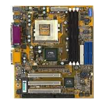
Introduction 1-2 MAINBOARD LAYOUT 1-2.1 Mainboard Layout --- 65KIV FAN1 ATX POWER Clock Generator VT82C694X JBAT1 AGP 4X PCI 1 AC'97 Codec PCI 2 VT82C 686A JWOL1 PCI 3 Using non-compliant memory with higher bus clock (over-clocking) may severely compromise the reliability of system. -
Page 14: 1-2.2 Mainboard Layout
65KIV/KIV2 1-2.2 Mainboard Layout --- 65KIV2 FAN1 ATX POWER Clock Generator VT82C694X JBAT1 AGP 4X PCI 1 AC'97 Codec PCI 2 VT82C 686B JWOL1 PCI 3 Using non-compliant memory with higher bus clock (over-clocking) may severely compromise the reliability of system. -
Page 15: Mainboard Specification Table Of 65Kiv & 65Kiv2
Introduction 1-3 MAINBOARD SPECIFICATION TABLE OF 65KIV & 65KIV2 Model 65KIV 65KIV2 North bridge VIA VT82C694X APOLLO PRO 133A Sorth bridge VIA VT82C686A VIA VT82C686B Supports PC133 and PC100 FP, SDRAM and Virtual Channel Memory Memory (VCM) up to 1.5GB 3 DIMM Slots AGP Interface AGP 4X Mode... -
Page 16: Chipset System Block Diagram
65KIV/KIV2 1-4 CHIPSET SYSTEM BLOCK DIAGRAM Socket 370 AGP 4X Slot Main 3D Graphics VT82C Memory Controller 694X (DRAM) Hardware Keyboard Monitoring & Mouse AC'97 IDEx2 Codec VT82C 686A/686B PM Control , USBx4 GPIO , Reset Super lO Serial Port x 2 BIOS Infrared Port x 1 Parallel Port x 1... - Page 17 Introduction MEMO MEMO...
-
Page 18: Chapter 2 Hardware Setup
65KIV/KIV2 CHAPTER HARDWARE SETUP ATTENTION !!! 1. Please refer to your processor installation or other documentation attached to your CPU for more detailed installing instruction. 2. Installing a heat sink and cooling fan is necessary for proper heat dissipation from your CPU. Incorrect in- stallation may result in overheating and damage of your CPU. -
Page 19: Cpu Installation
Hardware Setup 2-1 CPU INSTALLATION WARNING !!! • Make sure that +5V DCV and +3.3 DCV of your power supply are suitable for the processor. • Any attempt to operate the AMD Athlon or Duron processor without a suitable cooling Fan will damage processor and other component. Pull out the lever from the socket, and then raise the lever up to a 90-degree angle. -
Page 20: Memory Installation
65KIV/KIV2 2-2 MEMORY INSTALLATION WARNING!!! • Make sure to unplug your power supply before adding or removing memory modules or other system components. Failure to do so may cause severe damage to both your mainboard and expansion cards. • Be careful when inserting or removing DIMM. Forcing a DIMM in or out of a socket improperly may damage the memory module or the socket. -
Page 21: Accelerated Graphics Port(Agp) Pro Installation
Hardware Setup 2-3 ACCELERATED GRAPHICS PORT(AGP) PRO INSTALLATION • The AGP Pro connector is an extension of the existing AGP connector and it is compatible with existing AGP cards. AGP Accelerator CAUTION!! The AGP Pro slot comes with a warning label over the 20-pin bay. Do not remove this label and the safety tab underneath if you use an AGP card without a retention notch. -
Page 22: Hdd/Fdd Installation
65KIV/KIV2 2-4 HDD/FDD INSTALLATION • To install HDD (Hard Disk Drive), you may connect the cable’s blue connector to the mainboard’s primary (IDE1) or secondary (IDE2) connector, and then connect the gray connector to your slave device and the black connector to your master device. - Page 23 Hardware Setup • To install FDD (Floppy Disk Drive), you may connect the end with single connector to the board , and connect the other and with two plugs to the floppy drives. FAN1 ATX POWER Clock Generator VT82C694X JBAT1 AGP 4X PCI 1 AC'97...
-
Page 24: Switch Setting For Cpu Ratio And Clock
65KIV/KIV2 2-5 SWITCH SETTING FOR CPU RATIO AND CLOCK 2-5.1 CPU BUS RATIO SELECT • Normally, the Bus Ratio (Frequency Multiplier) of your processor is locked by processor’s Vendor and setting of the CPU Bus Ratio will have no effect. •... -
Page 25: 2-5.2 Bus Clock Select
Hardware Setup 2-5.2 BUS CLOCK SELECT • Over clocking is not recommended, your system may work unstable. • SW1 DIP5~8 settings for FSB (Front Side Bus) Frequency Select is a redundancy device designed for professional CPU overclocking only. Since this mainboard is designed with CPU clock auto-detection function, you are recommended to use the SW1 DIP5~8 default setting for a stable system performance. -
Page 26: Jumper Setting For Devices On Board
65KIV/KIV2 2-6 JUMPER SETTING FOR DEVICES ON BOARD • The following diagrams show the locations of jumper blocks on the mainboard. CAUTION • Do not remove the jumper when power is on. Always make sure the power is off before changing any jumpers. Otherwise, mainboard could be damaged. -
Page 27: 2-6.2 Jp5/Jp6 Usb Port Select
Hardware Setup 2-6.2 JP5/JP6 USB Port Select JP5/JP6 setting is for future use when there is a need to connect USB2 and to AGP port. Currently USB port to AGP is not connected. Please keep JP5/JP6 default setting at 2-3 closed for enabling USB2. Changing the default setting will disable the USB2. -
Page 28: 2-6.3 Jbat1 For Clear Cmos Data
65KIV/KIV2 2-6.3 JBAT1 For Clear CMOS DATA A battery should be used to supply the power for the CMOS RAM to retain the mainboard configuration. FAN1 ATX POWER Clock Generator JBAT1 For Clear CMOS DATA: Clear CMOS VT82C694X Data JBAT1 JBAT1 AGP 4X Retain Data... -
Page 29: Connectors Configurations
Hardware Setup 2-7 CONNECTORS CONFIGURATIONS • This section list out all connectors configurations for users’ reference. 2-7.1 On Board FAN Connector (FAN1, FAN2, FAN3) FAN1 ATX POWER On Board FAN Connector (FAN1): Clock Generator On Board FAN Connector (FAN2): VT82C694X On Board FAN Connector (FAN3): JBAT1... -
Page 30: 2-7.2 Wol1 Wake On Lan
65KIV/KIV2 2-7.2 WOL1 Wake On LAN FAN1 ATX POWER +5V standby Clock Generator VT82C694X Wake On LAN: JBAT1 AGP 4X PCI 1 AC'97 Connect the Wake Codec PCI 2 On LAN signal from VT82C 686A JWOL1 LAN card to JWOL1 JWOL1 PCI 3 This connector is connected to the LAN card with a Wake On LAN output. -
Page 31: 2-7.3 Cd-Rom Audio Connector (Cd_In1/Cd_In2)
Hardware Setup 2-7.3 CD-ROM Audio Connector (CD_IN1/CD_IN2) CD-ROM Audio Connector: FAN1 ATX POWER CD_IN1 CD_IN2 PIN NO. Left Clock Generator PIN 1 Channel Left PIN 2 Channel VT82C694X PIN 3 JBAT1 AGP 4X PCI 1 Right Right AC'97 PIN 4 Codec Channel Channel... -
Page 32: 2-7.4 Thermal Sensor Connector (Rt2)
65KIV/KIV2 2-7.4 Thermal Sensor Connector (RT2) Thermal Sensor Connector FAN1 ATX POWER (RT2): Clock Generator VT82C694X JBAT1 AGP 4X PCI 1 AC'97 Codec PCI 2 VT82C 686A JWOL1 PCI 3 We provide a thermal cable in the mainboard package. This thermal cable is to monitor device which will generates a lot of heat, such as HDD, Graphics card etc. -
Page 33: 2-7.5 Complex Header Con1
Hardware Setup 2-7.5 Complex Header CON1 • This complex Header consists of 9 connectors providing various supports: CON1 15 15 SUSPEND LED SMI SIGNAL SUSPEND LED SIGNAL POWER SWITCH ATX POWER SWITCH NO CONNECTION NO CONNECTION NO CONNECTION POWER LED NO CONNECTION NO CONNECTION INFRARED(IR) -
Page 34: 2-7.6 Atx Power Supply Connector
65KIV/KIV2 6. Power LED Connector: CONNECTION: Connected to System Power LED. FUNCTION: To supply power to “System Power LED”. 7. Reset Switch Connector: CONNECTION: Connected to the case-mounted “Reset Switch”. FUNCTION: To supply power to “Reset Switch” and support system re- boot function. -
Page 35: 2-7.7 Chassis Panel Connector
Hardware Setup 2-7.7 Chassis Panel Connector A : PS/2 MOUSE PORT B : USB 0 PORT C : LPT1 PORT D : GAME/MIDI PORT E : PS/2 KEYBOARD PORT F : USB 1 PORT G : COM1 PORT H : COM2 PORT : LINE OUT / SPEAKER OUT PORT J : LINE IN K : MICROPHONE... -
Page 36: 2-7.8 Usb2 Header
65KIV/KIV2 2-7.8 USB2 Header • This header is for connecting the additional USB cable to provides you additional two USB ports. User can order the additional USB cable from your mainboard dealer and vender. Additional USB Cable (Optional) Black Black Green Green White... -
Page 37: Irq Description
Hardware Setup 2-8 IRQ DESCRIPTION Function Description Priority IRQ 0 System Timer IRQ 1 Keyboard Controller IRQ 2 Programmable Interrupt IRQ 3 Serial Port (COM 2) IRQ 4 Serial Port (COM 1) IRQ 5 IRQ 6 Floppy Disk Controller IRQ 7 Parallel Port (LPT1) IRQ 8 Real Time Clock (RTC) - Page 38 65KIV/KIV2 MEMO MEMO...
-
Page 39: Chapter 3 Software Setup
Software Setup CHAPTER SOFTWARE SETUP ABOUT SUPPORT CD • In Support CD, it contains most informations for user’s requirement, such as Acrobat Reader, BIOS, User’s full version Manual, Driver, Hardware Monitor (if mainboard supports this function), Patch, and Utilities etc. User can browse the CD and get further details in regard of our mainboard. -
Page 40: Via Chipset Driver Installation (4-In-1 Driver)
65KIV/KIV2 3-1 VIA CHIPSET DRIVER INSTALLATION (4-IN-1 DRIVER) • Please put the Support CD • When a welcome window provided in your mainboard appears on the screen, package into the CD-ROM users should choose “Install drive. Driver”. • Click on the “VIA Chipset •... - Page 41 Software Setup • Press select the checkbox as below: Bus Master PCI IDE Driver AGP VxD Driver VIA Chipset Function’s Registry IRQ Routing Miniport Driver Next Note: For user who is upgrading VIA Drivers, we recommend to install the 4-in-1 as it will automatically detect and update the necessary drivers. •...
- Page 42 65KIV/KIV2 • Select “Install VIA AGP Next VxD” in turbo mode and press Next button to co- ntinue. • Select “Install VIA IRQ Routing Miniport Driver” Next checkbox, then click the “Next” button to continue. • After all these setup pro- cedures have finished, Finish lease restart your computer...
-
Page 43: Ac'97 Audio Codec Driver Installation
Software Setup 3-2 AC’97 AUDIO CODEC DRIVER INSTALLATION • Please put the Support CD • When a welcome window provided in your mainboard appears on the screen, package into the CD-ROM users should choose “Install drive. Driver”. • Click on the “VIA Chipset •... -
Page 44: Hardware Monitor Installation
65KIV/KIV2 3-3 HARDWARE MONITOR INSTALLATION • Please put the Support CD • When a welcome window provided in your mainboard appears on the screen, package into the CD-ROM users should choose “Install drive. Driver”. • Click on the “VIA Chipset •... - Page 45 Software Setup MEMO MEMO...
-
Page 46: Chapter 4 Bios Setup
65KIV/KIV2 CHAPTER BIOS SETUP THE BIOS • BIOS stands for Basic Input and Output System. It is sometimes called ROM BIOS because it is stored in a Read-Only Memory(ROM) chip on the mainboard. BIOS is the first program to run when you turn on your computer. -
Page 47: What Is Bios Setup
BIOS Setup 4-1 WHAT IS BIOS SETUP • BIOS setup is an interactive BIOS program that you need to run when: 1. Changing the hardware of your system. (For example: installing a new Hard Disk etc.) 2. Modifying the behavior of your computer. (For example: changing the system time or date, or turning special features on or off etc.) 3. -
Page 48: 4-5.1 Before Upgrading Bios
65KIV/KIV2 • The upgrade utility can be loaded on a floppy diskette and used to provide the capability to save, verify, and update the system BIOS. The upgrade utility can be run from a hard disk drive or a network drive. 4-5.1 Before Upgrading BIOS •... - Page 49 BIOS Setup Step 4. Type awdflash *.bin /sn/py/cc and then press <Enter> to run BIOS upgrade program. (*.bin depends on your mainboard model and version code. Instead of typing “*”, you should type specific file name for your specific mainboard). Step 5.
- Page 50 65KIV/KIV2 Award Flash Memory Writer Start Screen Award Flash Memory Writer Complete Screen...
- Page 51 BIOS Setup The parameters of AWDFLASH.EXE /sn: No original BIOS backup /py: Program flash memory /cc: Clear CMOS data (and update data automatically) after pro- gramming NOTE: Users can type AWDFLASH /? to get further details about the parameters. Incorrect usage of the parameter will damage the BIOS information, so we strongly recommend user to leave parameters alone unless you fully understand their function.
-
Page 52: Bios Setup
65KIV/KIV2 4-6 BIOS SETUP --- CMOS SETUP UTILITY 4-6.1 CMOS SETUP UTILITY • This mainboard comes with the AWARD BIOS from AWARD Software Inc. Enter the CMOS Setup Utility Main Menu by: 1. Turn on or reboot your system. After a series of diagnostic checks, the following message will appear: PRESS <DEL>... -
Page 53: 4-6.2 Standard Cmos Setup
BIOS Setup 4-6.2 STANDARD CMOS SETUP • Standard CMOS Setup records some basic system hardware configuration and sets the system clock and error handling. You only need to modify the configuration values of this option if you want to change your system hardware configuration or when the data stored in the CMOS memory gets lost or damaged. - Page 54 65KIV/KIV2 Date (mm:dd:yy) The BIOS determines the day of the week from the other date information. This field is for information only. Press the left or right arrow key to move to the desired field (date, month, year). Press the PgUp or PgDn key to increment the setting, or type the desired value into the field.
- Page 55 BIOS Setup Base Memory Typically 640KB. Also called conventional memory. The DOS operating system and conventional applications use this area. Extended Memory Above the 1MB boundary. Early IBM personal computers could not use memory above 1MB, but current PCs and their software can use extended memory.
-
Page 56: 4-6.3 Advanced Bios Features
65KIV/KIV2 4-6.3 ADVANCED BIOS FEATURES • ADVANCED BIOS FEATURES improves your system performance or sets up system features according to your preference. Run the ADVANCED BIOS FEATURES as follows: 1. Choose “ADVANCED BIOS FEATURES” from the Main Menu and a screen with a list of options will appear: 2. - Page 57 BIOS Setup CMOS Setup Utility - Copyright (C) 1984-2001 Award Software Advanced BIOS Features Item Help Disabled Virus Warning CPU Internal Cache Enabled Menu Level External Cache Enabled Enabled CPU L2 Cache ECC Checking Process or Number Feature Disabled Quick Power On Self Test Enabled First Boot Device Floppy...
- Page 58 65KIV/KIV2 Virus Warning When enabled, you receive a warning message if a program (specifically, a virus) attempts to write to the boot sector or the partition table of the hard disk drive. You should then run an antivirus program. Keep in mind that this feature protects only the boot sector, not the entire hard drive.
- Page 59 BIOS Setup First/Second/Third/ The BIOS attempts to load the operating system from Other Boot Device the devices in the sequence selected in these items. The choices: Floppy; LS/ZIP; HDD; SCSI; CDROM; Disabled. Swap Floppy Drive When enabled, floppy drives A and B will be exchanging without any physical connection and modification on the cables.
- Page 60 65KIV/KIV2 Typematic Rate (Chars When the typematic rate setting is enabled, you can / Sec) select a typematic rate (the rate at which character repeats when you hold down a key) of 6, 8, 10, 12, 15, 20, 24, or 30 characters per second. Typematic Delay Choices: 250;...
-
Page 61: 4-6.4 Advanced Chipset Features
BIOS Setup 4-6.4 ADVANCED CHIPSET FEATURES • ADVANCED CHIPSET FEATURES is used to modify the values of chipset buffers. These buffers control the system options. Run the ADVANCED CHIPSET FEATURES as follows: 1. Choose “ADVANCED CHIPSET FEATURES” from the Main Menu and a list of option will appear: 2. - Page 62 65KIV/KIV2 CMOS Setup Utility - Copyright (C) 1984-2001 Award Software Advanced Chipset Features Item Help DRAM Timing By SPD Enabled DRAM Clock Host CLK Menu Level SDRAM Cycle Length Disabled Bank Interleave Memory Hole Disabled P2C/C2P Concurrency Enabled Disabled System BIOS Cacheable Video RAM Cacheabl Disabled AGP Aperture Size...
- Page 63 BIOS Setup DRAM Timing By SPD When this item Enabled, DRAM Timing is set by SPD. SPD (Serial Presence Detect) is located on the memory modules, BIOS reads information coded in SPD during system boot up. DRAM Clock The value represents the performance parameters of the installed memory chips (DRAM).
- Page 64 65KIV/KIV2 AGP Aperture Size Series of options are available: 4, 8, 16, 32, 64, 128 or 256 MB. Memory mapped and graphics data structures can reside in a Graphics Aperture. This area is like a linear buffer. BIOS will automatically report the starting address of this buffer to the O.S.
- Page 65 BIOS Setup CPU to PCI Write When this field is Enabled, writes from the CPU to Buffer the PCI bus are buffered, to compensate for the speed differences between the CPU and the PCI bus. When Disabled, the writes are not buffered and the CPU must wait until the write is complete before starting another write cycle.
-
Page 66: 4-6.5 Integrated Peripherals
65KIV/KIV2 4-6.5 INTEGRATED PERIPHERALS • INTEGRATED PERIPHERALS option allows you to get some information inside your system when it is working. Run the INTEGRATED PERIPHERALS as follows: 1. Choose “INTEGRATED PERIPHERALS” from the Main Menu and a list of options will appear: 2. - Page 67 BIOS Setup CMOS Setup Utility - Copyright (C) 1984-2001 Award Software Integrated Peripherals On-Chip IDE Channel 0 Item Help Enabled On-Chip IDE Channel 1 Enabled Menu Level IDE Prefetch Mode Enabled Primary Master PIO Auto Primary Slave PIO Auto Secondary Master PIO Auto Secondary Slave PIO Auto...
- Page 68 65KIV/KIV2 On-Chip IDE channel The chipset contains a PCI IDE interface with support from two IDE channels. Select Enabled to activate the first and/or the second IDE interface. Select Disabled to deactivate an interface if you install a primary and/or second add-on IDE interface. The choices: Enabled (default);...
- Page 69 BIOS Setup Onboard FDD Select Enabled if your system has a floppy drive Controller controller (FDC) installing in the system board and you want to use it. If you install add-in FDC or the system has no floppy drive, select Disabled in this field.
- Page 70 65KIV/KIV2 Parallel Port Mode Select an operating mode for the on-board parallel (printer) port. Select Normal, Compatible, or SPP unless you are certain your hardware and software both support one of the other available modes. ECP Mode Use DMA Select a DMA channel for the port. Parallel Port EPP Type Select EPP port type 1.7 or 1.9, as required by your parallel peripheral.
-
Page 71: 4-6.6 Power Management Setup
BIOS Setup 4-6.6 POWER MANAGEMENT SETUP • POWER MANAGEMENT SETUP allows you to set the system’s power saving functions. Run the POWER MANAGEMENT SETUP as follows: 1. Choose “POWER MANAGEMENT SETUP” from the Main Menu and a list of options will appear: CMOS Setup Utility - Copyright (C) 1984-2001 Award Software Power Management Setup Item Help... - Page 72 65KIV/KIV2 ACPI Function Select Enabled only if your computer’s operating system supports the Advanced Configuration and Power Interface (ACPI) specification. Currently, Windows NT 5.0 supports ACPI. POWER MANAGEMENT • When this option is chosen, the following item appears for user’s configuration. CMOS Setup Utility - Copyright (C) 1984-2001 Award Software Power Management Item Help...
- Page 73 BIOS Setup * HDD Power Down When enabled and after the set time of system inactivity, the hard disk drive will be powered down while all other devices remain active. * Doze Mode After the selected period of system inactivity, the CPU clock runs at slower speed while all other devices still operate at full speed.
- Page 74 65KIV/KIV2 MODEM Use IRQ Name the interrupt request (IRQ) line assigned to the modem (if any) on your system. Activity of the selected IRQ always awakens the system. The choices: 3; 4; 5; 7; 9; 10; 11; NA. Doze Mode When enabled and after the set time of system inactivity, the CPU clock will run at slower speed while all other devices still operate at full speed.
-
Page 75: Wake Up Events
BIOS Setup WAKE UP EVENTS • When this option is chosen, the following item appears for user’s configuration. CMOS Setup Utility - Copyright (C) 1984-2001 Award Software Wake Up Events Item Help LPT/COM Menu Level LPT & COM HDD & FDD PCI Master Disabled Modeam Ring Resume... - Page 76 65KIV/KIV2 * RTC Alarm Resume When Enabled, you can set the data and time at which the RTC (Real Time Clock) alarm awakens the system from suspend mode. The choices: Disabled (default); Enabled. * Date (of Month) Set a certain date when RTC Alarm Resume option is Enabled to awaken the system.
- Page 77 BIOS Setup * IRQ ACTIVITY MONITORING • When this option is chosen, the following item appears for user’s configuration. CMOS Setup Utility - Copyright (C) 1984-2001 Award Software IRQ Activity Monitoring IRQ-3 (COM2) Enabled Item Help IRQ-4 (COM1) Enabled Menu Level IRQ-5 (LPT2) Enabled IRQ-6 (Floppy Disk)
-
Page 78: 4-6.7 Pnp / Pci Configuration
65KIV/KIV2 4-6.7 PNP / PCI CONFIGURATION • PNP/PCI CONFIGURATION allows you to modify the system’s power saving functions. Run the PNP/PCI CONFIGURATION as follows: 1. Choose “PNP/PCI CONFIGURATION” from the Main Menu and a screen with a list of options will appear: CMOS Setup Utility - Copyright (C) 1984 - 2001 Award Software PnP/PCI Configurations PNP OS Installed... - Page 79 BIOS Setup PNP OS Installed Select Yes if the system operating environment is Plug-and-Play aware (e.g., Windows95). NOTE: BIOS will automatically disable all PnP resources except the boot device card when you select Yes on Non-PnP operating system. Reset Configuration Normally, you leave this Disabled.
- Page 80 65KIV/KIV2 DMA Resources Press Enter at this item to reveal the following list: CMOS Setup Utility - Copyright (C) 1984 - 2001 Award Software DMA Resources DMA-0 assigned to PCI/ISA PnP Item Help DMA-1 assigned to PCI/ISA PnP Menu Level DMA-3 assigned to PCI/ISA PnP DMA-5 assigned to...
-
Page 81: 4-6.8 Pc Health Status
BIOS Setup 4-6.8 PC HEALTH STATUS • This section helps you to get more information about your system including CPU temperature, FAN speed and voltage. It is recommended that you contact your mainboard supplier to get proper values about the setting of the CPU temperature. Run the “PC Health Status”... - Page 82 65KIV/KIV2 Current CPU Temp. Shows current CPU temperature. Current System Temp. Shows current system temperature. Current CPU FAN1 Shows current CPU FAN1 speed. The fan must pro- Speed vide rotary pulse. (Normally these types of fan have a three-wire connector) Current CPUFAN2 Shows current CPUFAN2 speed.
-
Page 83: 4-6.9 Frequency/Voltage Control
BIOS Setup 4-6.9 FREQUENCY/VOLTAGE CONTROL Run the “FREQUENCY/VOLTAGE CONTROL” as following: 1. Choose “FREQUENCY/VOLTAGE CONTROL” from the Main Menu and a screen with a list of options will appear: CMOS Setup Utility - Copyright (C) 1984-2001 Award Software Frequency Control Item Help Auto Detect DIMM/PCI CLK Disabled... - Page 84 65KIV/KIV2 Auto Detect To reduce the occurrence of electromagnetic DIMM/PCI CLK interference (EMI), the BIOS detects the presence or absence of components in DIMM and PCI slots and turns off system clock generator pulses to empty slots. Spread Spec- When the system clock generator pulses, the ex- trum treme values of the pulse generate excess EMI.
-
Page 85: 4-6.10 Load Optimized Defaults
BIOS Setup 4-6.10 LOAD OPTIMIZED DEFAULTS • When you press <Enter> on this item, you will get a confirmation dialog box with a message similar to: “ L o a d O p t i m i z e d D e f a u l t s ( Y / N ) ? N ” “Y”... -
Page 86: 4-6.11 Set Supervisor / User Password
65KIV/KIV2 4-6.11 SET SUPERVISOR / USER PASSWORD • These two options allow you to set your system passwords. Normally, the supervisor has a higher priority to change the CMOS setup option than the users. The way to set up the passwords for both Supervisor and Users are as follows: 1. -
Page 87: 4-6.12 Save & Exit Setup
BIOS Setup 4-6.12 SAVE & EXIT SETUP • SAVE & EXIT SETUP allows you to save all modifications you have specified into the CMOS memory. Highlight this option on the Main Menu and the following message appears: “SAVE to CMOS and EXIT (Y/N) ? Y “... - Page 88 65KIV/KIV2 MEMO MEMO...
-
Page 89: Appendices
APPENDICES APPENDICES This chapter contains the following topics : APPENDIX-1 TECHNICAL TERMS INTRODUCTION APPENDIX-2 IDENTIFYING BIOS VERSION/ BIOS PART NUMBER APPENDIX-3 IDENTIFYING MAINBOARD MODEL NUMBER... -
Page 90: Appendix-1 Technical Terms Introduction
65KIV/KIV2 APPENDIX-1 TECHNICAL TERMS INTRODUCTION Technical Terms Introduction Tech Term Meaning Accelerated Graphic Port Audio Modem Riser Advanced Communication Riser Central Processing Unit CMOS Complementary Metal Oxide Semiconductor CRIMM Continuity RIMM Communication and Networking Riser Direct Memory Access Desktop Management Interface DIMM Dual Inline Memory Module DRAM... -
Page 91: Appendix-2 Identifying Bios Version And Bios Part Number
APPENDICES APPENDIX-2 IDENTIFYING BIOS VERSION AND BIOS PART NUMBER • When you boot up your computer, you may see a screen which tells your computer is phoenixnet™ enabled. Please see Picture-1 below for an illustration. • When the screen shows up press “Tab” key for BIOS information. Picture-1... - Page 92 65KIV/KIV2 • See Picture-2 below for BIOS version and BIOS part number identification. Picture-2 BIOS VERSION example: REV T2.1 BIOS ID STRING example: 6A69RSNCC...
-
Page 93: Appendix-3 Identifying Mainboard Model Number
APPENDICES APPENDIX-3 IDENTIFYING MAINBOARD MODEL NUMBER • Usually the mainboard model number is labeled on the ISA side of slot or PCI slot, please see the picture shown below for an illustration. MAINBOARD MODEL NUMBER example: SL-65KV2 MAINBOARD SERIAL NUMBER example: 0012000T005679... - Page 94 65KIV/KIV2 MEMO MEMO...
Need help?
Do you have a question about the SL-65KIV and is the answer not in the manual?
Questions and answers