Table of Contents
Advertisement
Advertisement
Table of Contents

Subscribe to Our Youtube Channel
Related Manuals for SOLTEK SL-75KAV


Summary of Contents for SOLTEK SL-75KAV
- Page 1 SL-75KAV/75KAV-X USER MANUAL V 1.2...
- Page 2 In no event shall Soltek computer inc. be liable for any loss or profits, loss of business, loss of use or data, interruption of business, or for indirect, special, incidental, or con- sequential damages of any kind, even if Soltek computer inc.
-
Page 3: Soltek Computer Inc
SOLTEK AROUND THE WORLD SOLTEK COMPUTER INC. Address : 7F, No. 306-3, Ta-Tung Rd, Sec.1, Hsi-Chih, Taipei- Hsien, Taiwan, R.O.C. Telephone : 886-2-2642-9060 : 886-2-2642-9065 E-mail : sales@soltek.com.tw Web site : http://www.soltek.com.tw SOUL TECHNOLOGY EUROPE B.V. Address : Hongkongstraat 55, 3047 BR, Rotterdam, The... -
Page 4: Table Of Contents
75KAV/75KAV-X C O N T E N T Chapter 1 Introduction ..........9 1-1 MAINBOARD SPECIFICATION ..........10 1-1-1 PROCESSOR ................... 10 1-1-2 CHIPSET ................... 10 1-1-3 ADVANCED HIGH PERFORMANCE DRAM CONTROLLER ... 10 1-1-4 FULL FEATURED ACCELERATED GRAPHICS PORTS ....10 (AGP) CONTROLLER .............. - Page 5 Content 2-6-1 JUMPER JBAT1 FOR CLEARING CMOS DATA: ......27 2-6-2 JP1/JP2 USB PORT SELECT ............28 2-6-3 JP3 FOR FACTORY TEST ONLY ............. 28 2-6-4 JP7 POWER LOST RESUME ............29 2-6-5 JP9 USB WAKE UP ................29 2-6-6 JP10/JP11 MEMORY MODULE VOLTAGE SELECT ....... 30 2-7 CONNECTORS CONFIGURATIONS .........
- Page 6 75KAV/75KAV-X 4-5 BIOS UPGRADE ................. 56 4-5-1 BEFORE UPGRADING BIOS ............57 4-5-2 UPGRADE PROCESS ..............57 4-6 BIOS SETUP°XCMOS SETUP UTILITY ........61 4-6-1 STANDARD CMOS SETUP .............. 62 4-6-2 ADVANCED BIOS FEATURES ............65 4-6-3 ADVANCED CHIPSET FEATURES ..........70 4-6-4 INTEGRATED PERIPHERALS ............
- Page 7 Content MEMO...
- Page 8 75KAV/75KAV-X ITEMLIST CHECKUP Mainboard Support CD User’s Manual Bundled Bonus Pack CD Bundled Bonus Pack Manual Temperature Sensor Cable ATA66/100 IDE Cable RS232 Cable FDD Cable...
-
Page 9: Chapter 1 Introduction
Chapter1 Introduction CHAPTER INTRODUCTION • This chapter briefly introduces the characteristics of this mainboard. It includes the information regarding the chipset, CPU types, built-in functions and layout. Users will have more ideas about mainboards after reading this chapter. THIS CHAPTER CONTAINS THE FOLLOWING TOPICS : N J N=MAINBOARD SPECIFICATION N J O=MAINBOARD LAYOUT N J P=CHIPSET DIAGRAM... -
Page 10: Mainboard Specification
75KAV/75KAV-X 1-1 MAINBOARD SPECIFICATION 1-1-1 PROCESSOR • Supporting AMD Athlon Thunderbird processors up to 1.5GHz. • Supporting AMD Athlon Duron processors up to 1.2GHz. • Supporting processor VID (voltage ID) and FID (frequency ID) auto detection. • Supporting AMD Athlon processor with 200 and 266MHz Front Side bus. 1-1-2 CHIPSET •... -
Page 11: Expansion Slots
Chapter1 Introduction --Standard mode, ECP and EPP. • Floppy Disk connector supporting: --Two FDDs with drive swap function. • Universal Serial Bus connector supporting: --USB v1.1 and Intel Universal HCI v1.1 compatible. --2 built-in USB connectors, in addition to one internal USB header which requires a USB cable to support 2 more optional USB ports. -
Page 12: Form Factor
75KAV/75KAV-X • Supporting USB boot-up Function. 1-1-10 FORM FACTOR • ATX form factor, 4 layer PCB. • Mainboard size: 22.0cm x 30.5cm. 1-1-11 HARDWARE MONITORING • Programmable control, status, to provide monitoring and alarm for flexible desktop management of hardware temperature. (software included in sup- port CD) •... -
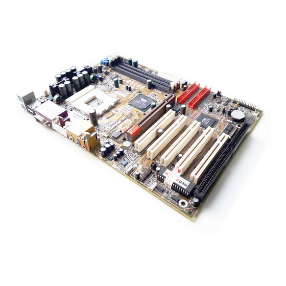
Page 13: Mainboard Layout
Chapter1 Introduction 1-2 MAINBOARD LAYOUT 1-2-1 MAINBOARD LAYOUT --- 75KAV • Default Setting: 100MHz CPU External clock. FAN1 5 4 3 2 1 4 3 2 1 ATX POWER SSF1 JP17 JP10 SOCKET A JP11 Clock Generator KT-133A VT8363A FAN3 COM 2 AGP PRO 4X IDE1... -
Page 14: Mainboard Layout
75KAV/75KAV-X 1-2-2 MAINBOARD LAYOUT --- 75KAV-X • Default Setting: 100MHz CPU External clock. FAN1 5 4 3 2 1 4 3 2 1 ATX POWER SSF1 JP17 JP10 SOCKET A JP11 Clock Generator KT-133A VT8363A FAN3 COM 2 AGP PRO 4X IDE1 CD_IN2 PCI 1... -
Page 15: Chipset Diagram
Chapter1 Introduction 1-3 CHIPSET DIAGRAM • The KT-133A / VT82C686B chipset is a high performance, cost-effective and energy efficient system controller for the implementation of AGP / PCI / ISA desktop personal computer system based on 64-bit Socket-A (AMD Athlon) processors. SYSCLK, SYSCLK# Athlon INTR, NMI, SMI#, STPCLK#,... - Page 16 75KAV/75KAV-X MEMO...
-
Page 17: Chapter 2 Hardware Setup
Chapter2 Hardware Setup CHAPTER HARDWARE SETUP ATTENTION !!! 1. Please refer to your processor installation or other documentation attached with your CPU for more detailed installing instruction. 2. Installing a heat sink and cooling fan is necessary for proper heat dissipation from your CPU. Incorrect installation may result in overheating and damage of your CPU. -
Page 18: Cpu Installation
75KAV/75KAV-X 2-1 CPU INSTALLATION WARNING: • Make sure that +5V DCV and +3.3 DCV capabilities of your power supply are suitable for the processor. • Any attempt to operate the AMD Athlon or Duron processor without a suitable cooling Fan will damage the processor and other components. •... -
Page 19: Memory Installation
Chapter2 Hardware Setup • Make sure that the CPU is placed into the socket tightly. Then lower down the lever to complete the CPU installation. 2-2 MEMORY INSTALLATION FAN1 5 4 3 2 1 4 3 2 1 NOTICE : When LED “ZD1”... -
Page 20: Installing Dimm
75KAV/75KAV-X WARNING!!! • Make sure to unplug your power supply before adding or removing memory mod- ules or other system components. Failure to do so may cause severe damage to both your mainboard and expansion cards. • Be careful when inserting or removing DIMM. Forcing a DIMM in or out of a socket improperly may damage the memory module or the socket. -
Page 21: Accelerated Graphics Port(Agp) Pro Installation
Chapter2 Hardware Setup 2-3 ACCELERATED GRAPHICS PORT(AGP) PRO INSTALLATION • The AGP Pro connector is an extension of the existing AGP connec- tor and it is compatible with existing AGP cards. AGP Accelerator AGP Pro slot blockader Accelerated Graphics Port (AGP) Pro Slot 20-pin bay Rib(inside slot) 28-pin bay Rib(inside slot) -
Page 22: Hdd/Fdd Installation
75KAV/75KAV-X 2-4 HDD/FDD INSTALLATION • To install HDD (Hard Disk Drive), you may connect the cable’s blue con- nector to the mainboard’s primary (IDE1) or secondary (IDE2) connector, and then connect the gray connector to your slave device and the black connector to your master device. - Page 23 Chapter2 Hardware Setup • To install FDD (Floppy Disk Drive), connect the end with single connector to the mainboard, and connect other end with two connectors to the floppy drives. FAN1 5 4 3 2 1 4 3 2 1 ATX POWER SSF1 JP17...
-
Page 24: Switch Setting For Cpu Frequency And Voltage
75KAV/75KAV-X 2-5 SWITCH SETTING FOR CPU FREQUENCY AND VOLTAGE 2-5-1 INFORMATION ON AMD SOCKET 462 PROCESSOR • On the AMD socket 462 processor, you can find a codified identification marking which is to provide useful information about the CPU. The mark- ing is interpreted as bellow: XXXXXXXXXXX XXXXXXXXXXXX... -
Page 25: Cpu External Frequency Setting (By Sw1)
Chapter2 Hardware Setup 2-5-2 CPU EXTERNAL FREQUENCY SETTING (BY SW1) CPU EXTERNAL PCI FREQUENCY FSB FREQUENCY FREQUENCY 5 4 3 2 1 100MHz 200MHz 33.3MHz (default) 5 4 3 2 1 103MHz 34.3MHz 206MHz 5 4 3 2 1 210MHz 105MHz 35.0MHz 5 4 3 2 1... -
Page 26: Bus Ratio Select (By Sw2 Dip1-4/Jp17)
75KAV/75KAV-X 2-5-3 BUS RATIO SELECT (BY SW2 DIP1-4/JP17) • The AMD Athlon and Duron processors provide four Frequency ID signals (FID) respectively via DIP 1 to DIP4 of SW3 for the system controller to specify the SYSTCLK multiplier at which the processor core operates. Normally, the multiplier (or bus ratio) is detected automatically by FID. -
Page 27: Jumper Setting For Devices On Board
Chapter2 Hardware Setup 2-6 JUMPER SETTING FOR DEVICES ON BOARD: • The following diagrams show the location for jumper blocks on the mainboard. CAUTION • Do not remove the jumper when power is on. Always make sure the power is off before changing any jumpers. Otherwise, mainboard could be damaged. -
Page 28: Jp1/Jp2 Usb Port Select
75KAV/75KAV-X 2-6-2 JP1/JP2 USB PORT SELECT FAN1 5 4 3 2 1 4 3 2 1 Redirect USB port 3 to USB 2 ATX POWER SSF1 JP17 connector (default) JP10 SOCKET A JP11 Clock Generator Redirect USB port 3 to AGP KT-133A VT8363A FAN3... -
Page 29: Jp7 Power Lost Resume
Chapter2 Hardware Setup 2-6-4 JP7 POWER LOST RESUME FAN1 5 4 3 2 1 4 3 2 1 ATX POWER SSF1 Normal (default) JP17 JP10 SOCKET A JP11 Clock Generator Enabled KT-133A VT8363A FAN3 COM 2 AGP PRO 4X This jumper allows you to use the switch of ATX IDE1 CD_IN2 PCI 1... -
Page 30: Jp10/Jp11 Memory Module Voltage Select
75KAV/75KAV-X 2-6-6 JP10/JP11 MEMORY MODULE VOLTAGE SELECT FAN1 5 4 3 2 1 4 3 2 1 JP10 ATX POWER SSF1 3.3V (default) JP11 JP17 JP10 SOCKET A JP11 Clock Generator JP10 3.4V JP11 JP10 3.5V JP11 KT-133A VT8363A FAN3 COM 2 JP10 AGP PRO 4X... -
Page 31: Connectors Configurations
Chapter2 Hardware Setup 2-7 CONNECTORS CONFIGURATIONS • This section lists out all connectors configurations for users’ reference: 2-7-1 ONBOARD FAN CONNECTOR (FAN1/FAN2/FAN3) FAN1 5 4 3 2 1 4 3 2 1 CPU FAN FAN1 ATX POWER SSF1 JP17 JP10 SYSTEM FAN FAN2 SOCKET A... -
Page 32: Wake On Lan Function (Wol1)
75KAV/75KAV-X 2-7-2 WAKE ON LAN FUNCTION (WOL1) FAN1 5 4 3 2 1 4 3 2 1 Connect the Wake On LAN ATX POWER SSF1 WOL1 signal from LAN card JP17 JP10 to WOL1 SOCKET A JP11 Clock Generator +5V standby KT-133A VT8363A FAN3... -
Page 33: Thermal Sensor Connector (Rt2)
Chapter2 Hardware Setup 2-7-4 THERMAL SENSOR CONNECTOR (RT2) FAN1 5 4 3 2 1 4 3 2 1 ATX POWER SSF1 JP17 JP10 SOCKET A JP11 Clock Generator KT-133A VT8363A FAN3 COM 2 AGP PRO 4X IDE1 CD_IN2 PCI 1 CD_IN1 AC'97 IDE2... -
Page 34: Header J3&J4
75KAV/75KAV-X 2-7-5 HEADER J3&J4 • Header J3&J4 includes seven connectors for different functions: A1 : 1st HDD LED A2 : 2nd HDD LED A1 A2 B : INFRARED (IR) C : POWER SWITCH D : None E : SPEAKER F : RESET SWITCH G : POWER LED H : NONE : SUSPEND LED... - Page 35 Chapter2 Hardware Setup 1 2 3 4 5 6 7 8 9 10 11 12 13 14 15 INFRARED CONNECTOR INFRARED TRANSMIT SIGNAL PIN 6 PIN 7 PIN 8 INFRARED RECEIVE SIGNAL PIN 9 NONE PIN 10 This connector supports an optional wireless transmitting and receiving infrared module.
- Page 36 75KAV/75KAV-X 1 2 3 4 5 6 7 8 9 10 11 12 13 14 15 SPEAKER CONNECTOR PIN 1 SPEAKER SIGNAL PIN 2 NONE PIN 3 PIN 4 This connector connects to the case-mounted speaker. Two sources (LINE OUT and SPEAKER) DESCRIPTION allow you to hear system beeps and warnings.
-
Page 37: Chassis Panel Connector
Chapter2 Hardware Setup 1 2 3 4 5 6 7 8 9 10 11 12 13 14 15 SUSPEND LED CONNECTOR PIN 14 SUSPEND LED SIGNAL PIN 15 DESCRIPTION Connect to Suspend indicator light. 2-7-6 CHASSIS PANEL CONNECTOR A : PS/2 MOUSE PORT B : USB O PORT C : LPT 1 PORT D : GAME/MIDI PORT... -
Page 38: Atx Power Supply Connector
75KAV/75KAV-X 2-7-7 ATX POWER SUPPLY CONNECTOR • This connector is connected to an ATX power supply by a plug from the power supply. The plug can only be inserted in a specific orientation be- cause of the different hole sizes. Find the proper orientation and push down the plug firmly to make sure that all pins are aligned. -
Page 39: Serial Port Connector
Chapter2 Hardware Setup 2-7-9 SERIAL PORT CONNECTOR • The first serial port COM1 is ready for a mouse or other serial devices. The second serial port COM2 is available by using a RS232 serial cable con- necting from the mainboard to an expansion slot opening. FAN1 COM2 5 4 3 2 1... -
Page 40: Second Usb Header (Usb2)
75KAV/75KAV-X 2-7-10 SECOND USB HEADER (USB2) • This header is for the additional USB cable to provide you two additional USB ports. Users can order the additional USB cable from your mainboard dealers or venders. Additional USB Cable (Optional) Black Black Green Green... -
Page 41: Irqs Description For Various Devices
Chapter2 Hardware Setup 2-7-11 IRQ DESCRIPTION FOR VARIOUS DEVICES Function Description Priority IRQ 0 System Timer IRQ 1 Keyboard Controller IRQ 2 Programmable Interrupt IRQ 3 Serial Port (COM 2) IRQ 4 Serial Port (COM 1) IRQ 5 IRQ 6 Floppy Disk Controller IRQ 7 Parallel Port (LPT1) -
Page 42: Voice Diagnostic Function
75KAV/75KAV-X 2-8 VOICE DIAGNOSTIC FUNCTION----ONLY FOR 75KAV-X • The Voice Diagnostic Function provides user an indispensable assistance on troubleshooting while assembling your computer components. If there is any conflict or other latent problem that triggers a boot-up failure, this new VD- TECH technology will voice you realistically where the conflict/problem is, then users can remove the malfunction quickly. -
Page 43: Voice Diagnostic Function Select (By Jp4/Jp5)
Chapter2 Hardware Setup 2-8-1 VOICE DIAGNOSTIC FUNCTION SELECT (BY JP4/JP5) FAN1 5 4 3 2 1 4 3 2 1 ATX POWER SSF1 To select Chinese JP17 JP10 SOCKET A JP11 Clock Generator To select English (default) To select Japanese KT-133A VT8363A FAN3... - Page 44 75KAV/75KAV-X MEMO...
-
Page 45: Chapter 3 Software Setup
Chapter3 Software Setup CHAPTER SOFTWARE SETUP ABOUT SUPPORT CD • In support CD, it contains most information for users’ requirement, such as Acrobat Reader, BIOS, Users’ full version Manual, Driver, Hardware Monitor (if mainboard supports this function), Patch, and Utilities etc., User can browse the CD and get further details in re- gard of our mainboard. -
Page 46: Via Chipset Driver Installation (4-In-1 Driver)
75KAV/75KAV-X 3-1 VIA CHIPSET DRIVER INSTALLATION (4-IN-1 DRIVER) • Please put the Support CD • Click on the “VIA Chipset into the CD-ROM drive. Driver”. • When a welcome window appears on the screen, choose “Install Driver”. • Click on the “4-in-1 driver”. •... - Page 47 Chapter3 Software Setup • Press select the checkbox as below: Bus Master PCI IDE Driver AGP VxD Driver VIA Chipset Function’s Regis try Install IRQ Routing Miniport Driver Note: For users who are upgrading VIA Drivers, we recommend to install the 4-in-1 as it will automatically detect and update the necessary drivers.
- Page 48 75KAV/75KAV-X • Select “Install VIA AGP VxD” in turbo mode and press Next button to continue. Next • Select “Install VIA IRQ Routing Miniport Driver” checkbox, then click the “Next” button to continue. Next • After all these setup proce- dures have finished, please restart your computer by clicking on Finish.
-
Page 49: Ac97 Audio Codec Driver Installation
Chapter3 Software Setup 3-2 AC97 AUDIO CODEC DRIVER INSTALLATION • Please put the Support CD • Click on the “VIA chipsets into the CD-ROM drive. Driver”. • When a welcome window appears on the screen, choose “Install Driver”. • Click on the “AC’97 driver”. •... - Page 50 75KAV/75KAV-X • Please click the “Finish” button to complete setup. Finish...
-
Page 51: Hardware Monitor Installation
Chapter3 Software Setup 3-3 HARDWARE MONITOR INSTALLATION • Please put the Support CD • Click on the “VIA chipsets into the CD-ROM drive. Driver”. • When a welcome window appears on the screen, choose “Install Driver”. • Click on the “Hardware Monitor Utility”. - Page 52 75KAV/75KAV-X • Press Next button to finish the Hardware Monitor setup process. Next...
- Page 53 Chapter3 Software Setup MEMO...
- Page 54 75KAV/75KAV-X MEMO...
-
Page 55: Chapter 4 Bios Setup
Chapter4 BIOS Setup CHAPTER BIOS SETUP THE BIOS • BIOS stands for Basic Input and Output System. It is sometimes called ROM BIOS because it is stored in a Read-Only Memory (ROM) chip on the mainboard. BIOS is the first program to run when you turn on your computer. •... -
Page 56: What Is Bios Setup
75KAV/75KAV-X 4-1 WHAT IS BIOS SETUP • BIOS Setup is an interactive BIOS program that you need to run when: 1. Changing the hardware of your system. (for example: installing a new Hard Disk etc..) 2. Modifying the behavior of your computer. (for example: changing the sys- tem time or date, or turning special features on or off etc..) 3. -
Page 57: Before Upgrading Bios
Chapter4 BIOS Setup replace an EPROM component. • The upgrade utility can be loaded on a floppy diskette and used to provide the capability to save, verify, and update the system BIOS. The upgrade utility can also be run from a hard disk drive or a network drive. 4-5-1 BEFORE UPGRADING BIOS •... - Page 58 75KAV/75KAV-X specific mainboard.) Step 5. Please press <F1> or <F10> to exit or reset your system, Warning ! If the message “Write Fail” appears while Award “FLASH MEMORY WRITER” is verifying Flash memory, just repeat the process. Please DO NOT reset or turn off the system.
- Page 59 Chapter4 BIOS Setup Figure 4-5-1 Award Flash Memory Writer Start Screen Figure 4-5-2 Award Flash Memory Writer Complete Screen...
- Page 60 75KAV/75KAV-X The parameters of AWDFLASH.EXE /sn: No original BIOS backup /py: Program flash memory /cc: Clear CMOS data (and update data automatically) after programming NOTE: Users can type AWDFLASH /? to get further details about the parameters. Incorrect usage of the parameter will damage the BIOS information, so we strongly recommend users to leave parameters alone unless you fully understand their function.
-
Page 61: Bios Setup°Xcmos Setup Utility
Chapter4 BIOS Setup 4-6 BIOS SETUP CMOS SETUP UTILITY • This mainboard comes with the AWARD BIOS from AWARD Software Inc. Enter the CMOS Setup Utility Main Menu by: 1. Turn on or reboot your system. After a series of diagnostic checks, the following message will appear: PRESS <DEL>... -
Page 62: Standard Cmos Setup
75KAV/75KAV-X 4-6-1 STANDARD CMOS SETUP • Standard CMOS Setup records some basic system hardware configuration and sets the system clock and error handling. You only need to modify the configuration values of this option if you want to change your system hard- ware configuration or when the data stored in the CMOS memory gets lost or damaged. - Page 63 Chapter4 BIOS Setup Date (mm:dd:yy) The BIOS determines the day of the week from the other date information. This field is for information only. Press the left or right arrow key to move to the de- sired field (date, month, year). Press the PgUp or PgDn key to increment the setting, or type the de- sired value into the field.
- Page 64 75KAV/75KAV-X Halt On Set this warning feature for the type of errors that will cause the system to halt. The choices are: All Errors; Post stops for all error. No Errors; Post does not stop for any error. All, But Keyboard; Post stops for all, but not for keyboard error.
-
Page 65: Advanced Bios Features
Chapter4 BIOS Setup 4-6-2 ADVANCED BIOS FEATURES • ADVANCED BIOS FEATURES improves your system performance or sets up system features according to your preference. Run the ADVANCED BIOS FEATURES as follows: 1. Choose “ADVANCED BIOS FEATURES” from the Main Menu and a list of option will appear: 2. - Page 66 75KAV/75KAV-X CMOS Setup Utility - Copyright (C) 1984-2001 Award Software Advanced BIOS Features Item Help Virus Warning Disabled Menu Level CPU Internal Cache Enabled External Cache Enabled CPU L2 Cache ECC Checking Enabled Quick Power On Self Test Enabled First Boot Device Floppy Second Boot Device HDD-0...
- Page 67 Chapter4 BIOS Setup Virus Warning Enabled: Activates automatically when the system boots up showing a warning message if anything attempts to access the boot sec- tor or hard disk partition table. Disabled: No warning message will appear when there is something attempting to access the boot sector or hard disk partition table.
- Page 68 75KAV/75KAV-X Boot Up Floppy Seek Enabled : During POST, BIOS checks the track num- ber of the floppy disk drive to see whether it is 40 or 80 tracks. Disabled: During POST, BIOS will not check the track number of the floppy disk drive. Boot Up NumLock Toggle between On or Off to control the state of the Status...
- Page 69 Chapter4 BIOS Setup Video BIOS Shadow Performance will be improved by copying Video BIOS to Shadow RAM. C8000-CBFFF to These options are used to copy firmware from other DC000-DFFFF Shadow expansion card ROMs to system RAM. 3. Press <ESC> to return to the Main Menu when you finish setting up all items.
-
Page 70: Advanced Chipset Features
75KAV/75KAV-X 4-6-3 ADVANCED CHIPSET FEATURES • ADVANCED CHIPSET FEATURES is used to modify the values of chipset registers. These registers control the system options. Run the ADVANCED CHIPSET FEATURES as following: 1. Choose “ADVANCED CHIPSET FEATURES” from the Main Menu and a list of option will appear: 2. - Page 71 Chapter4 BIOS Setup CMOS Setup Utility - Copyright (C) 1984-2001 Award Software Advanced Chipset Features Item Help DRAM Timing By SPD Enabled Menu Level DRAM Clock 100MHZ SDRAM Cycle Length Bank Interleave Disabled DRAM Drive Strength Auto DRAM Drive Value Memory Hole Disabled PCI Master Pipeline Req...
- Page 72 75KAV/75KAV-X DRAM Timing by SPD When this item is Enabled, DRAM Timing is set by SPD (Serial Presence Detect) is located on the memory modules, BIOS reads information coded in SPD during system boot up. DRAM Clock The value represents the performance parameters of the installed memory chips (DRAM).
- Page 73 Chapter4 BIOS Setup Fast R-W Turn Around This item controls the DRAM timing. It allows you to enable / disable the fast read / write turn around. The choices: Enabled; Disabled. System BIOS selecting Enabled allows caching of the system BIOS Cacheable ROM at F0000h-FFFFFh, resulting in better system performance.
- Page 74 75KAV/75KAV-X USB Keyboard Enable function when the USB keyboard is being Support used. When the AT keyboard is being used, choose disabled. OnChip Sound Select Enabled to use the on-chip Audio capability of your system. Most of the following field do not appear when this field is Disabled.
-
Page 75: Integrated Peripherals
Chapter4 BIOS Setup 4-6-4 INTEGRATED PERIPHERALS • INTEGRATED PERIPHERALS option allows you to get some information inside your system when it is working. Run the INTEGRATED PERIPHERALS as follows: 1. Choose “INTEGRATED PERIPHERALS” from the Main Menu and a list of option will appear: CMOS Setup Utility - Copyright (C) 1984-2001 Award Software Integrated Peripherals... - Page 76 75KAV/75KAV-X 2. Use one of the arrow keys to move between options and modify the se- lected options by using PgUp / PgDn / + / - keys. <F1>: “Help” gives options available for each item. <F5>: Get the previous values. These values are the values with which the user starts the current session.
- Page 77 Chapter4 BIOS Setup IDE HDD Block Mode Block mode is also called block transfer, multiple commands, or multiple sector read/write. If your IDE hard drive supports block mode (most new drives do), select Enabled for automatic detection of the optimal number of block read/write per sector the drive can support.
- Page 78 75KAV/75KAV-X Parallel Port Mode Select an operating mode for the onboard parallel (printer) port. Select Normal, Compatible, or SPP unless you are certain your hardware and software both support one of the other available modes. The choices: SPP; EPP; ECP; ECP + EPP. ECP Mode Use DMA Select a DMA channel for the parallel port for use during ECP mode.
-
Page 79: Power Management Setup
Chapter4 BIOS Setup 4-6-5 POWER MANAGEMENT SETUP • POWER MANAGEMENT SETUP allows you to set the system’s power saving functions. Run the POWER MANAGEMENT SETUP as follows: 1. Choose “POWER MANAGEMENT SETUP” from the Main Menu and a list of option will appear: CMOS Setup Utility - Copyright (C) 1984-2001 Award Software Power Management Setup ACPI Function... - Page 80 75KAV/75KAV-X ACPI Function Select Enabled only if your computer’s operating sys- tem supports the Advanced Configuration and Power Interface (ACPI) specification. • Press <Enter> on the Power Management item, then there appears a list of options for you to configure further setting. CMOS Setup Utility - Copyright (C) 1984-2001 Award Software Power Management Power Management...
- Page 81 Chapter4 BIOS Setup HDD Power Down When enabled and after the set time of system inactivity, the hard disk drive will be powered down while all other devices remain active. Doze Mode When enabled and after the set time of system inactivity, the CPU clock will run at slower speed while all other devices still operate at full speed.
- Page 82 75KAV/75KAV-X l l i c i t MODEM Use IRQ This determines the IRQ which the MODEM can use. The choices: 3; 4; 5; 7; 9; 10; 11; NA. Soft-Off by PWRBTN When Enabled, turning the system off by pressing the on/off button places the system in a very low- power-usage state.
- Page 83 Chapter4 BIOS Setup CMOS Setup Utility - Copyright (C) 1984-2001 Award Software Wake Up Events Item Help LPT & COM LPT/COM Menu Level HDD & FDD PCI Master Wake Up On LAN/Ring Disabled RTC Alarm Resume Disabled Date (of Month) Resume Time (hh:mm:ss) Primary INTR IRQ Activity Monitoring...
- Page 84 75KAV/75KAV-X RTC Alarm Resume When Enabled, you can set the data and time at which the RTC (Real Time Clock) alarm awakens the sys- tem from suspend mode. The choices: Disabled; Enabled. Date (of Month) Set a certain date when RTC Alarm Resume option is Enabled to awaken the system.
- Page 85 Chapter4 BIOS Setup CMOS Setup Utility - Copyright (C) 1984-2001 Award Software IRQ Activity Monitoring IRQ 3 (COM2) Enabled Item Help IRQ 4 (COM1) Enabled Menu Level IRQ 5 (LPT2) Enabled IRQ 6 (Floppy Disk) Enabled IRQ 7 (LPT1) Enabled IRQ 8 (RTC Alarm) Disabled IRQ 9 (IRQ2 Redir)
-
Page 86: Pnp / Pci Configuration
75KAV/75KAV-X 4-6-6 PNP / PCI CONFIGURATION • PNP/PCI CONFIGURATION allows you to modify the system’s power sav- ing functions. Run the PNP/PCI CONFIGURATION as follows: 1. Choose “PNP/PCI CONFIGURATION” from the Main Menu and a list of option will appear: CMOS Setup Utility - Copyright (C) 1984-2001 Award Software PnP/PCI Configurations PNP OS Installed... - Page 87 Chapter4 BIOS Setup PNP OS Installed Select Yes if the system operating environment is Plug-and Play aware (e.g., Windows 95). NOTE: BIOS will automatically disable all PnP resources except the boot device card when you select Yes on Non-PnP operating system. Reset Configuration Normally, you leave this Disabled.
- Page 88 75KAV/75KAV-X DMA Resources Press Enter. Please refer to the list below: CMOS Setup Utility - Copyright (C) 1984-2001 Award Software DMA Resources Item Help DMA-0 assigned to PCI/ISA PnP DMA-1 assigned to PCI/ISA PnP Menu Level DMA-3 assigned to PCI/ISA PnP DMA-5 assigned to PCI/ISA PnP DMA-6 assigned to...
- Page 89 Chapter4 BIOS Setup PCI SLOT1/5, 2/6, 3, 4 These options allow you to assign an IRQ for each IRQ Assigned PCI SLOT and this is a useful function when you want to clear the IRQ conflict for a specific device. The op- tions are available: Auto;...
-
Page 90: Smartdoc Anti-Burn Shield
75KAV/75KAV-X 4-6-7 SMARTDOC ANTI-BURN SHIELD • This section helps you to get more information about your system including CPU temperature, FAN speed and voltage. It is recommended that you contact your mainboard supplier to get proper values about the setting of the CPU temperature. - Page 91 Chapter4 BIOS Setup CPU Warning Temp. User can select CPU warning temperature in this field. When CPU Temperature is higher than value you select in this field, the BIOS will send out sequence of beeps or send out a warning message “your CPU temperature is too high”.
- Page 92 75KAV/75KAV-X Vcore/VDD/3.3V/5V/ Shows actual voltage value of power supply. • Press <ESC> to return to the Main Menu when you finish setting up all items.
-
Page 93: Frequency/Voltage Control
Chapter4 BIOS Setup 4-6-8 FREQUENCY/VOLTAGE CONTROL Run the “FREQUENCY/VOLTAGE CONTROL” as follows: 1. Choose “FREQUENCY/VOLTAGE CONTROL” from the Main Menu and a list of option will appear: CMOS Setup Utility - Copyright (C) 1984-2001 Award Software Frequency Control Item Help Redstorm Overclocking Tech Press Enter Auto Detect DIMM/PCI Clk... - Page 94 75KAV/75KAV-X Redstorm Press <Enter> to start RED STORM Overclocking OVERCLOCKING TECH. This option offers users an Tech easier way to overclocking, and it will increase CPU external clock automatically. When CPU external clock is increased to an unacceptable value, BIOS will restart your system, and then run at acceptable CPU external clock.
-
Page 95: Load Optimized Defaults
Chapter4 BIOS Setup 4-6-9 LOAD OPTIMIZED DEFAULTS • When you press <Enter> on this item, you will get a confirmation dialog box with a message similar to: “ Load Optimized Defaults (Y / N) ? N ” “Y” is for “Yes”, and “N” is for “No”. •... -
Page 96: Set Supervisor / User Password
75KAV/75KAV-X 4-6-10 SET SUPERVISOR / USER PASSWORD • These two options allow you to set your system passwords. Normally, the supervisor has a higher priority to change the CMOS setup option than the users. The way to set up the passwords for both Supervisor and Users are as follows: 1. -
Page 97: Save & Exit Setup
Appendices 4-6-11 SAVE & EXIT SETUP • SAVE & EXIT SETUP allows you to save all modifications you have speci- fied into the CMOS memory. Highlight this option on the Main Menu and the following message appears: “SAVE to CMOS and EXIT (Y/N) ? Y “... -
Page 98: Appendices
75KAV/75KAV-X APPENDICES THIS CHAPTER CONTAINS THE FOLLOWING TOPICS : APPENDICES-1 TECHNICAL TERMS INTRODUCTION APPENDICES-2 IDENTIFYING BIOS VERSION/ BIOS PART NUMBER APPENDICES-3 IDENTIFYING MAINBOARD MODEL NUMBER... -
Page 99: Appendices-1 Technical Terms Introduction
Appendices APPENDICES-1 TECHNICAL TERMS INTRODUCTION Technical Terms Introduction Tech Term Meaning Accelerated Graphic Port Audio Modem Riser Advanced Communication Riser Central Processing Unit CMOS Complementary Metal Oxide Semiconductor CRIMM Continuity RIMM Communication and Networking Riser Direct Memory Access Desktop Management Interface DIMM Dual Inline Memory Module DRAM... -
Page 100: Appendices-2 Identifying Bios Version And
75KAV/75KAV-X APPENDICES-2 IDENTIFYING BIOS VERSION AND BIOS PART NUMBER When you boot up your computer, you may see a screen which tells your computer is phoenixnet™ enabled, please see the example below. When the main screen Figure1 shows up, press “Tab” key to display BIOS information (Figure2). - Page 101 Appendices Figure2 shown below displays the BIOS version and BIOS part number identification. Figure 2 BIOS VERSION example: REV T2.1 BIOS ID STRING example: 6A69RSNCC...
-
Page 102: Appendices-3 Identifying Mainboard \ Model
75KAV/75KAV-X APPENDICES-3 IDENTIFYING MAINBOARD \ MODEL NUMBER Usually the mainboard model number is labeled on the side of ISA slot or PCI slot, please see the picture shown below: MAINBOARD MODEL NUMBER example: SL-65KV2 MAINBOARD SERIAL NUMBER example: 0012000T005679... - Page 103 Appendices MEMO...
- Page 104 75KAV/75KAV-X MEMO...
Need help?
Do you have a question about the SL-75KAV and is the answer not in the manual?
Questions and answers