Table of Contents
Advertisement
Quick Links
Advertisement
Table of Contents

Related Manuals for SOLTEK SL-56H5


Summary of Contents for SOLTEK SL-56H5
-
Page 1: User Manual
T h e S o u l C o m p u t e r T e c h n o l o g y SL-56H5 / H1 USER MANUAL... - Page 2 In no event shall Soltek computer inc. Be liable for any loss or profits, loss of business, loss of use or data, interruption of business, or for indirect, special, incidental, or con- sequential damages of any kind, even if Soltek computer inc.
-
Page 3: Soltek Computer Inc
SOLTEK AROUND THE WORLD SOLTEK COMPUTER INC. Address : 7F, No. 306-3, Ta-Tung Rd, Sec. 1, Hsi-Chih, Taipei- Hsien, Taiwan, R.O.C. Telephone : 886-2-2642-9060 : 886-2-2642-9065 E-mail : sashia@soltek.com.tw Web site : http://www.soltek.com.tw SOLTEK KOREA INC. Address : 1002, Chungjin Bldg. 53-5 Wonhyo-Ro, 3-Ka,... -
Page 4: Table Of Contents
56H5 / 56H1 C O N T E N T SOLTEK COMPUTER INC..........3 SOLTEK KOREA INC............3 MOKA HOLDING B.V............3 SOUL TECHNOLOGY EUROPE B.V......3 CHAPTER 1 INTRODUCTION ..........6 1-1 ITEM LIST CHECKUP ............. 6 1-2 CPU.................. - Page 5 2-3.3 2nd USB CONNECTOR ..........14 2-3.4 ATX POWER SUPPLY CONNECTOR ...... 15 CHAPTER 3 SOFTWARE SETUP ........... 16 3-1 ABOUT SOLTEK SUPPORT CD ........16 3-2 HARDWARE MONITOR INSTALLATION ...... 16 3-3 VIA CHIPSET DRIVER INSTALLATION (4-in1 Driver) 18 CHAPTER 4 BIOS SETUP ............
-
Page 6: Chapter 1 Introduction
1-1 ITEM LIST CHECKUP • Soltek Motherboard • Soltek Support CD • Soltek User’s Manual • Soltek 2-in-1 Bonus Pack CD • Soltek 2-in-1 Bonus Pack Manual • 1.44MB floppy ribbon cable • Ribbon cable for master and slave UltraDMA/33&UltraDMA/66 IDE... -
Page 7: Bios Description
56H5 / 56H1 • Provides 3 pcs of 168pin DIMM sockets(3.3V unbuffered 4 clock type). 1-5 BIOS DESCRIPTION • Award BIOS. • Supports Plug & Play (PnP). • FLASH MEMORY for easy upgrade. • Supports Advanced Power Management (APM) Rev 1.2 function. •... -
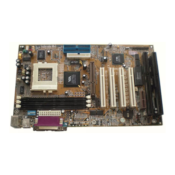
Page 8: Motherboard Layout
56H5 / 56H1 1-7 MOTHERBOARD LAYOUT • Motherboard Default Setting: AMD K6-2 350/100MHz JFAN1 Clock Generator Pipelined Burst SRAM Pipelined Burst SRAM Apollo MVP3 USB2 JP10 JP11 PCI 1 PCI 2 PCI 3 686A PCI 4 Battery JP12 JFAN2 FLASH BIOS JP15 ISA1 JWOL1... - Page 9 56H5 / 56H1 WATCH OUT !!! 1. Please refer to your processor installation or other documentation attached with your CPU for detailed installing instruction. 2. Installing a heat sink and cooling fan is necessary for proper heat dissipation from your CPU. Uncor- rected installation may result in overheating and damage of your CPU.
-
Page 10: Hardware Setup
56H5 / 56H1 CHAPTER 2 HARDWARE SETUP 2-1 VOLTAGE ADJUSTMENT • CPU Vcore Setting Vcore Vcore Vcore Vcore Voltage Voltage Voltage Voltage 3.2V 2.4V 2.8V 2.0V K6-III MMX, 6x86L K6-2 233 2.9V 3.3V 2.1V 2.5V K6 166/200 IDT C6 6x86MX(MII) 2.2V 3.4V 2.6V... -
Page 11: Cpu Bus Ratio Setting
56H5 / 56H1 NOTE: Only new clock generator(W83194R-58A) supports 95MHz/ 97MHz. Please check with your dealer before using this clock. • CPU Bus Ratio Setting CPU BUS RATIO SELECT 2.0x / 6.0x 2.5x 3.0x 1.5x / 3.5x 1 2 3 4 5 6 1 2 3 4 5 6 1 2 3 4 5 6 1 2 3 4 5 6... -
Page 12: Jp10 / Jp11: Usb Port Select
56H5 / 56H1 • JP10 / JP11: USB Port Select USB Port JP10 / JP11 Redirect USB port2 to USB JP10 connector (default) JP11 JP10 Redirect USB port2 to AGP JP11 • JP12: Clear CMOS Data CMOS Status JP12 Clear CMOS Data Retain Data (default) •... -
Page 13: Connectors
56H5 / 56H1 2-3 CONNECTORS • In this sector we list all external connectors that user may use. 2-3.1 J2 / J3 A : HDD LED B : INFRARED (IR) C : POWER SWITCH D : SUSPEND CONNECTOR E : SPEAKER F : RESET SWITCH G : POWER LED H : NONE... -
Page 14: 2-3.3 2Nd Usb Connector
PIN 13 D1+ (Green) PIN 14 N/A PIN 15 GND (Black) PIN 16 N/A Soltek 2nd USB Connector (Optional) • When plugs the 2nd USB connector to USB2 port, user can see every color of wires to determine which is the first pin. -
Page 15: 2-3.4 Atx Power Supply Connector
56H5 / 56H1 2-3.4 ATX POWER SUPPLY CONNECTOR • This connector connects to an ATX power supply. The plug from the power supply only inserts in an orientation because of the different hole sizes. Find the proper orientation and push down firmly making sure that all pins are aligned. -
Page 16: Chapter 3 Software Setup
SOFTWARE SETUP 3-1 ABOUT SOLTEK SUPPORT CD • In Soltek support CD, it contains most informations for user’s requirement, such as Acrobat Reader, BIOS, User’s Manual, Driver, Hardware Monitor, Patch and Utility etc,. User can browse the CD and get further details in regard of your motherboard. - Page 17 56H5 / 56H1 Click on the “ INSTALL Hardware Monitor Utility “. Press Next to continue. The default setup destination is C:\VIAhm, press Next to continue. Press Next to finish the VIA Hardware Monitor setup process.
-
Page 18: Via Chipset Driver Installation (4-In1 Driver)
56H5 / 56H1 3-3 VIA CHIPSET DRIVER INSTALLATION (4-in1 Driver) Please put the CD attached to motherboard into the CD-ROM. There appears a welcome window as left screen. Click on “ INSTALL DRIVER “ item. Click on the “ INSTALL VIA CHIPSET DRIVER “. - Page 19 56H5 / 56H1 Click on “ Install 4in1 Driver” to continue. Press “ Next “ to continue. Press “ Yes “ to continue. Please select the checkbox as below. "Bus Master PCI IDE Driver "AGP VxD Driver #VIA Chipset Function’s Registry #IRQ Routing Miniport Driver Note: In Windows 95/98 environment, user doesn’t need to add “VIA Chipset Functions’...
- Page 20 56H5 / 56H1 Press Install to continue. We do not recommend user to select “ Enable/Disable [Ultra] DMA ”. Note: Whether select this item or not, user has to enable the Hard Disk DMA function in Control Panel manually. (For further details, please refer to next page) The default setup destination is C:\VIADMATOOL, press Next to continue.
- Page 21 56H5 / 56H1 Select “ Install VIA AGP VxD in turbo mode”. After all the setup process is finished, please restart your computer by clicking on Finish. bout Hard Disk DMA Function Last but not least, user has to enable the Hard Disk DMA function. The process is below: 1.
-
Page 22: Chapter 4 Bios Setup
56H5 / 56H1 CHAPTER 4 BIOS SETUP 4-1 INTRODUCE THE BIOS • BIOS stands for Basic Input Output System. It is sometimes call ROM BIOS because it is stored in a Read-Only Memory (ROM) chip on the motherboard. BISO is the first program to run when you turn on your computer. -
Page 23: What Is Cmos
56H5 / 56H1 4-4 WHAT IS CMOS • CMOS is a special kind of memory maintained by a battery after you turn your computer off. The BIOS uses CMOS to store the settings you selected in SETUP. The CMOS also maintains the intermal clock. Every time you turn on your computer, the BIOS looks in CMOS for the set- tings you selected and configures your computer accordingly. -
Page 24: 4-6.3 Common Errors
56H5 / 56H1 your CD-ROM drive. 5. Type COPY D:\UTILITY\AWDFLASH.EXE A:\ to copy the file AWDFLASH.EXE from CD-ROM to floppy disk, 6. Reboot your system from the floppy disk. 7. In the DOS mode, type awdflash xxx.bin /sn/py/cc/r and then press <Enter>... - Page 25 56H5 / 56H1 prefer the former page step 2. to format a pure bootable floppy disk. • BIOS part number doesn’t match: When the BIOS chip is damaged, it will trigger this error. The only way to solve it is to change a new BIOS chip.
-
Page 26: Cmos Setup Utility
56H5 / 56H1 4-7 CMOS SETUP UTILITY This VIA82C693A chipset Apollo Pro-Plus comes with the AWARD BIOS from AWARD Software Inc. Enter the AWARD BIOS program Main Menu by: 1. Turn on or reboot the system. After a series of diagnostic checks, the following message will appear: PRESS <DEL>... -
Page 27: 4-7.1 Standard Cmos Setup
56H5 / 56H1 4-7.1 STANDARD CMOS SETUP Standard CMOS Setup allows you to record some basic system hard- ware configuration and set the system clock and error handling. You only need to modify the configuration values of this option when you change your system hardware configuration or the configuration stored in the CMOS memory gets lost or damaged. - Page 28 56H5 / 56H1 Date (mm:dd:yy) Set the current date and time. Time (hh:mm:ss) Primary This field records the specification for all non-SCSI Hard (Secondary) Disk Drives installed in your system. Refer to the respec- tive documentation on how to install the drives. Drive A / B Set the field to the type(s) of Floppy Disk drive(s) installed in your system.
-
Page 29: 4-7.2 Bios Features Setup
56H5 / 56H1 4-7.2 BIOS FEATURES SETUP BIOS Features Setup allows you to improve your system performance or set up system features according to your preference. Run the BIOS Features Setup as follows: 1. Choose “BIOS FEATURES SETUP” from the Main Menu and a screen with a list of options will appear. - Page 30 56H5 / 56H1 Virus Warning Enabled: Activates automatically when the system boots up causing a warning message to appear if there is anything attempting to access the boot sec- tor or Hard Disk partition table. Disabled: No warning message will appear when there is something attempting to access the boot sec- tor or Hard Disk partition table.
- Page 31 56H5 / 56H1 Boot Up NumLock On (default): Activate the NumLock function at boot up. Status Off: Close the NumLock function at boot up. IDE HDD Block Choose Enabled (default) or Disabled. If your Hard Disk Mode size is larger than 540MB, choose Enabled, and if you are using the IDE HDD Auto Detection option, the BIOS will choose this option automatically.
- Page 32 56H5 / 56H1 Video BIOS Enabled (default): Map the VGA BIOS to system RAM. Shadow Disabled: Don’t map the VGA BIOS to system RAM. C8000-CBFFF to These options are used to shadow other expansion card DC000- ROMs. Cyrix 6x86 / MII Enabled: Default setting.
-
Page 33: 4-7.3 Chipset Features Setup
56H5 / 56H1 4-7.3 CHIPSET FEATURES SETUP Chipset Features Setup changes the values of the chipset registers. These registers control the system options. Run the Chipset Features Setup as follows: 1. Choose “CHIPSET FEATURES SETUP” from the Main Menu and a screen with a list of options will appear. - Page 34 56H5 / 56H1 Bank 0/1 2/3 4/5 This item allows you to select the value in this field, de- DRAM pending on whether the board has paged DRAMs or EDO (extended data output) DRAMs. The choice: EDO 50ns, EDO 60ns, Slow, Medium, Fast,...
- Page 35 56H5 / 56H1 OnChip Modem Enabled (default): Use MC99 feature. Disabled: Turn off MC99 feature. If user wants to use ex- ternal modem, this function must be disabled. OnChip USB This should be enabled if your system has a USB installed on the system board and you wish to use it.
-
Page 36: 4-7.4 Power Management Setup
56H5 / 56H1 4-7.4 POWER MANAGEMENT SETUP Power Management Setup changes the system power savings function. Run the Power Management Setup as follows: 1. Choose “POWER MANAGEMENT SETUP” from the Main Menu and a screen with a list of options will appear. 2. - Page 37 56H5 / 56H1 ACPI Function Enabled: Turn on ACPI function. Disabled (default): Turn off ACPI function. Power Manage- Choose Max. Saving, User Define (default), Disabled, or ment Min. Saving. PM Control By Choose Yes (default) or No. You need to choose Yes when the operating system has the APM functions, otherwise choose No.
- Page 38 56H5 / 56H1 When On of VGA, any activity from one of the listed sys- tem peripheral devices or IRQs wakes up the system. Choice: On(default), Off. LPT & COM When On of LPT&COM, any activity from one of the listed system peripheral devices or IRQs wakes up the system.
- Page 39 56H5 / 56H1 The following is a list of IRQ’s(Interrupt ReQuests), which can be exempted much as the COM ports and LPT ports above can. When an I/O device wants to gain the attention of the operating system, it signals this by causing an IRQ to occur. When the operating system is ready to respond to the request, it interrupts itself and performs the service.
-
Page 40: 4-7.5 Pnp/Pci Configuration
56H5 / 56H1 4-7.5 PnP/PCI CONFIGURATION PnP/PCI Configuration Setup defines PCI bus slots. Run the PnP/PCI Configuration Setup as follows: 1. Choose “PnP/PCI CONFIGURATION SETUP” from the Main Menu and a screen with a list of options will appear. 2. Use one of the arrow keys to move between options and modify the selected options by using PgUp/PgDn/+/- keys. - Page 41 56H5 / 56H1 PNP OS Installed Yes: OS supportsss Plug and Play function. No (default): OS doesn’t support Plug and Play function. Resources Choose Manual (default) or Auto. The BIOS checks the Controlled IRQ/DMA channel number on the ISA and PCI card manu- ally if you choose Manual.
- Page 42 56H5 / 56H1 Assign IRQ for Enabled (default): Add one IRQ to USB controller. Disabled: Remove IRQ from USB controller. The system will have extra IRQ for other devices but the USB controller will still not be diabled (only IRQ was removed) Assign IRQ for Enabled (default): Add one IRQ to VGA controller.
-
Page 43: 4-7.6 Load Setup Defaults
56H5 / 56H1 4-7.6 LOAD SETUP DEFAULTS Load Setup Defaults option loads the default system values to the system configuration fields. If the CMOS is corrupted the defaults are loaded automatically. Choose this option and the following message will appear: “Load Setup Defaults (Y/N)? N”... -
Page 44: 4-7.7 Integratedperipherals
56H5 / 56H1 4-7.7 INTEGRATEDPERIPHERALS Integrated Peripherals option changes the values of the chipset registers. These registers control system options in the computer. Run the Integrated Peripherals as follows: 1. Choose “INTEGRATED PERIPHERALS” from the Main Menu and a screen with a list of options will appear. 2. - Page 45 56H5 / 56H1 OnChip IDE The chipset contains a PCI IDE interface with support from Channel two IDE channels. Select Enabled to activate the first and/ or the second IDE interface. Select Disabled to deactivate an interface, if you install a primary and/or second add- on IDE interface.
- Page 46 56H5 / 56H1 UART 2 Mode Choose Standard (default), HPSIR or ASKIR. IR Function Duplex The choice: Half (default), Full TX, RX inverting Choose No, Yes (default) / No, No / Yes, No / Yes, Yes. enabled Onboard Paralle Choose the printer I/O address: 378H/IRQ7 (default), 3BCH/ Port IRQ7, 278H/IRQ5 or Disabled.
- Page 47 56H5 / 56H1 Sound Blaster Choose Enabled or Disabled (default). For DOS mode compatibility, this option must be enabled. In Windows system, this option must be disabled. SB I/O Base Use default setting. Address SB IRQ Select Use default setting. SB DMA Select Use default setting.
-
Page 48: 4-7.8 Supervisor/User Password
56H5 / 56H1 4-7.8 SUPERVISOR/USER PASSWORD These two options allow you to set your system passwords. Normally, the supervisor has a higher ability to change the CMOS setup option than the user. The way to set up the passwords for both supervisor and user are as follows: 1. -
Page 49: 4-7.9 Ide Hdd Auto Detection
56H5 / 56H1 4-7.9 IDE HDD AUTO DETECTION IDE HDD Auto Detection detects the parameters of an IDE Hard Disk drive and automatically enters them to the Standard CMOS Setup screen. The screen will ask you to select a specific Hard Disk for Primary Master after you selected this option.
Need help?
Do you have a question about the SL-56H5 and is the answer not in the manual?
Questions and answers