Table of Contents
Advertisement
Quick Links
Advertisement
Table of Contents

Subscribe to Our Youtube Channel
Related Manuals for Extreme Networks ExtremeWireless AP510e


Summary of Contents for Extreme Networks ExtremeWireless AP510e
- Page 1 ExtremeWireless™ AP510e Installation Guide 9035996-03 Rev AA April 2023...
- Page 2 Extreme Networks, Inc. reserves the right to make changes in specifications and other information contained in this document and its website without prior notice. The reader should in all cases consult representatives of Extreme Networks to determine whether any such changes have been made.
-
Page 3: Table Of Contents
Table of Contents Preface.............................. 5 Text Conventions....................................5 Providing Feedback to Us................................6 Getting Help......................................7 Subscribing to Service Notifications.......................... 8 Documentation and Training..............................8 Open Source Declarations..............................8 Training......................................8 Overview............................9 New in this Guide....................................9 April 2023 Revisions................................. 9 AP510e Features....................................10 AP510e Powering Methods.............................. - Page 4 Table of Contents AP510e BLE Antenna Information..........................44 AP510e Antenna Information............................44 AP510e Bluetooth Antenna Information......................46 AIO-DQ15021-RPSMA Antenna Information.....................46 Specifications..........................49 Physical Specifications.................................49 Environmental Specifications..............................49 Regulatory and Compliance Information................50 Safety Guidelines....................................50 FCC Declaration of Conformity Statement........................51 FCC Caution:....................................51 FCC Radiation Exposure Statement...........................51 FCC OEM Integrator Note................................
-
Page 5: Preface
Preface This section discusses the conventions used in this guide, ways to provide feedback, additional help, and other Extreme Networks® publications. Text Conventions Unless otherwise noted, information in this document applies to all supported environments for the products in question. Exceptions, like command keywords associated with a specific software version, are identified in the text. -
Page 6: Providing Feedback To Us
Providing Feedback to Us Quality is our first concern at Extreme Networks, and we have made every effort to ensure the accuracy and completeness of this document. We are always striving to ExtremeWireless™ AP510e... -
Page 7: Getting Help
Ideas for improvements to our documentation so you can find the information you need faster. • Broken links or usability issues. If you would like to provide feedback to the Extreme Networks Information Development team, you can do so in two ways: • Use our short online feedback form at https://www.extremenetworks.com/... -
Page 8: Subscribing To Service Notifications
Some software files have been licensed under certain open source licenses. More information is available at: www.extremenetworks.com/support/policies/open-source- declaration/. Training Extreme Networks offers product training courses, both online and in person, as well as specialized certifications. For more information, visit www.extremenetworks.com/ education/. ExtremeWireless™ AP510e... -
Page 9: Overview
Overview New in this Guide on page 9 AP510e Features on page 10 AP510e LEDs Status on page 13 The AP510e is a next generation, indoor ceiling mount model enterprise class 802.11ax access point (AP). The “e” in AP510e indicates that it comes with external antennas. The AP features dual-band radio, eight RP-SMA WiFi ports, one Bluetooth port, and one internal Bluetooth Low Energy (BLE) antenna. -
Page 10: Ap510E Features
AP510e Features Overview Table 4: New and revised information (continued) Description Section Compliance updates for the AIO-DQ15021- FCC Radiation Exposure Statement RPSMA antenna. Industry Canada Notice Detachable Antenna Usage AP510e Features The enterprise class 802.11ax AP510e access point has the following features: •... - Page 11 Overview AP510e Features Figure 1: Top view of AP510e Figure 2: Side view of AP510e ExtremeWireless™ AP510e...
-
Page 12: Ap510E Powering Methods
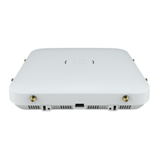
AP510e Powering Methods Overview Figure 3: AP510e back ports Table 5: Description of back ports of AP510e Number Description Kensington lock 12V DC power supply Console port GE 2 (GE) GE 1 (5 GE) AP510e Powering Methods You can power the AP through the RJ45 Ethernet port (LAN 1 (5GE) and LAN2 (GE) ports, see Figure 3 on page 12). -
Page 13: Ap510E Leds Status
Overview AP510e LEDs Status the AP. There is no wall mount bracket for the 12V DC power supply. When the device is powered on, the power LED on the front face of the AP is lit. Table 6: AP510e Powering Methods Power Source Description Power over Ethernet (PoE) - Page 14 LEDs Status Overview Figure 4: AP510e LEDs Table 7: AP510e LEDs Status LED Icon LED Color Description AP Status GREEN Normal operational status AMBER Non-operational status GE1 Ethernet AMBER 100 Mbps GREEN 1000 Mbps PURPLE 2.5G/5G GE2 Ethernet AMBER 100 Mbps GREEN 1000 Mbps Radio #1 Status...
-
Page 15: Install The Access Point
Install the Access Point Verify the Box Contents on page 15 Mount and Connect the AP on page 16 Mounting Brackets and Accessories Usage on page 16 Mount the AP on a Dry or Wood Wall/Solid Flat Ceiling on page 19 Mount to a Suspended/Drop Ceiling on page 29 Mount the AP to a Junction/Gang box... -
Page 16: Mount And Connect The Ap
AP510e access point Phillips pan-head wood screws Screw-in anchors 2. Perform a visual inspection of the access point for any physical damage. Contact Extreme Networks Support if there is any damage. Mount and Connect the AP Caution Only qualified personnel should perform installation procedures. - Page 17 Install the Access Point Mounting Brackets and Accessories Usage Table 9: Bracket purchase order information (continued) Part number Description 30516 WS-MBI-WALL04 bracket 37211 WS-MBI-DCFLUSH bracket Table 10: Bracket purchase order information Part number Description 37201 Main mounting bracket for indoor access points (included in the access point box), along with the 27 mm M3 security screw pack for main mounting bracket 30518...
- Page 18 Mounting Brackets and Accessories Usage Install the Access Point Table 13: Power supply purchase order information (continued) Part number Description 37215 Table 14: Bracket and accessory usage for various installation options Mounting Wall Solid Ceiling Ceiling Junction Beam Ceiling tile T-bar Notes bracket or...
-
Page 19: Mount The Ap On A Dry Or Wood Wall/Solid Flat Ceiling
Install the Access Point Mount the AP on a Dry or Wood Wall/Solid Flat Ceiling Table 14: Bracket and accessory usage for various installation options (continued) Mounting Wall Solid Ceiling Ceiling Junction Beam Ceiling tile T-bar Notes bracket or install flat install install... -
Page 20: Mount The Access Point To A Wall Using The Main Mounting Bracket
Mount the access point to a wall using the Main Mounting Bracket Install the Access Point Mount the access point to a wall using the Main Mounting Bracket About This Task The stainless-steel main mounting bracket (#37201) ships with the access point and can be used to mount the access point onto a wall. - Page 21 Mount the access point to a wall using the Main Install the Access Point Mounting Bracket 3. Insert the screws into the holes of the mounting bracket and use the screw-in anchors if needed. 4. Insert the Ethernet cable's RJ45 connector into the LAN1 port. ExtremeWireless™...
- Page 22 Mount the access point to a wall using the Main Mounting Bracket Install the Access Point 5. Insert the access point onto the bracket's four feet and slide it down to lock it in place. Figure 6: Main mounting bracket attachment holes on the access point Label Description Guide posts to attach the security torx...
- Page 23 Mount the access point to a wall using the Main Install the Access Point Mounting Bracket Figure 7: Mounting the access point onto the main mounting bracket 6. Attach the security torx locking screw to keep the main mounting bracket in place. For more information, see Install a Security Torx Locking Screw on page 23.
-
Page 24: Mount The Ap To A Wall Using The Ws-Mbi-Wall04 Bracket
Mount the AP to a wall using the WS-MBI-WALL04 bracket Install the Access Point Procedure 1. Line up the security torx locking screw using the rear guides on the access point. 2. Using a T10 bit screwdriver, tighten the security torx locking screw. 3. - Page 25 Mount the AP to a wall using the WS-MBI-WALL04 Install the Access Point bracket Procedure 1. Install the WS-MBI-WALL04 bracket on a wall or to a flat ceiling with the two screws and screw-in anchors. Ensure that the locking tab on the WS-MBI-WALL04 bracket is on the top side during installation.
-
Page 26: Easy-Attach Adaptor
Mount the AP onto a wall using the Main Mounting Bracket and the Flat Metal Easy-Attach adaptor Install the Access Point Figure 10: Mounting the access point using the WS-MBI-WALL04 bracket (when bracket corners are broken off) 2. Connect the LAN cable to the access point. 3. - Page 27 Mount the AP onto a wall using the Main Mounting Install the Access Point Bracket and the Flat Metal Easy-Attach adaptor Procedure 1. Attach the flat metal easy-attach adaptor to the main mounting bracket. Keep the easy-attach adaptor to the center of the main mounting bracket's hinges, push and rotate it.
-
Page 28: Mount The Access Point To A Wall Using The Phillips Pan-Head Screws
Mount the access point to a wall using the Phillips pan- head screws Install the Access Point 5. Connect the LAN cable to the back of the access point. 6. Hold the access point to the wall, insert the two screws onto the mounting holes of the flat metal easy-attach adaptor. -
Page 29: Mount To A Suspended/Drop Ceiling
Install the Access Point Mount to a Suspended/Drop Ceiling 4. Align the access point against the screw heads and slide it down. Ensure that the access point is secured in place and tightened. Note When installing the access point, the “E” logo on it must be pointing up. 5. -
Page 30: Mounting The Access Point Using The Main Mounting Bracket With Kt-135628-01
Mounting the access point using the Main Mounting Bracket with KT-135628-01 adaptor to a flat T-bar Install the Access Point 4. Replace the ceiling tiles. 5. Attach the Ethernet cable’s RJ45 connector to the LAN1 port. Mounting the access point using the Main Mounting Bracket with KT-135628-01 adaptor to a flat T-bar About This Task Mounting the access point to a suspended or a drop ceiling requires the optional... - Page 31 Mounting the access point using the WS-MBI- Install the Access Point DCFLUSH Bracket to a flat T-bar Procedure 1. Remove the ceiling panels around the drop ceiling T-bar rail. 2. Open the movable sliding part of the DCFLUSH bracket to give the stationary and slider T-bar more space.
-
Page 32: Mounting The Ap Using The Ws-Mbi-Dcmtr01 Bracket
Mounting the AP using the WS-MBI-DCMTR01 Bracket Install the Access Point 6. Slide the T-bar ceiling mount bracket base into the back of the access point. The locking tab fits into a groove in the outside of the access point. Figure 14: Attaching the DCFLUSH bracket to the access point 7. - Page 33 Install the Access Point Mounting the AP using the WS-MBI-DCMTR01 Bracket Procedure 1. Remove the ceiling panels around the drop ceiling T-bar rail. 2. Open the movable sliding part of the DCMTR01 bracket to give the stationary and slider T-bar more space. Figure 15: DCMTR01 bracket parts Label Description...
-
Page 34: Mount The Ap To A Junction/Gang Box
Mount the AP to a Junction/Gang box Install the Access Point 6. Slide the T-bar ceiling mount bracket base into the back of the access point. The locking tab fits into a groove in the outside of the access point. Figure 16: Attaching the access point onto the WS-MBI-DCMTR01 bracket 7. -
Page 35: Mount The Access Point To A Beam
Install the Access Point Mount the access point to a Beam 2. Line up the #37201 main mounting bracket holes on the junction/gang box and ensure that they align. If the holes do not align, then use the WS-MBI-WALL04 bracket. Note When you line up the holes, the locking tab on the WALL04 bracket must be pointing up and the junction/gang box must be fully covered by the... - Page 36 Mount the access point to a Beam Install the Access Point Procedure 1. Attach the beam clip accessory, BRKT-000147A-01 to the main mounting bracket by placing it between the center hinges of the main mounting bracket. Figure 17: Beam clip accessory, BRKT-000147A-01 2.
-
Page 37: Install The Aio-Dq15021-Rpsma Antenna
Install the Access Point Install the AIO-DQ15021-RPSMA Antenna 4. Place the beam clip accessory on a beam in such a way that there is enough space between the screw and clamp to be tightened. Figure 19: Attaching the beam clip accessory to the beam 5. - Page 38 Install the AIO-DQ15021-RPSMA Antenna Install the Access Point Confirm that the mounting hardware shipped with the antenna as listed in the table below. Note The AIO-DQ15021-RPSMA antenna is only supported on the AP510e. It is supported on ExtremeCloud™ IQ Controller and it is intended for indoor stadiums and arenas for a campus mode deployment only.
- Page 39 Install the Access Point Install the AIO-DQ15021-RPSMA Antenna For best results, mount the antenna in the center of the coverage area. A line-of-sight path between the antenna and the active area works best. Avoid mounting next to a column or vertical support that creates a shadow zone and reduces coverage. Note Install the antenna before you connect the cable so the cable is not twisted or damaged.
-
Page 40: Antenna Information
Antenna Information Supported Antennas on page 40 Operational Description of Antenna Configuration and RF Output Power Setting on page 41 Antenna configurations for external antenna models on page 42 AP510e Antenna Information on page 44 Supported Antennas The following table shows the antennas supported on the AP510e. Table 16: Supported antennas Brand Model name... -
Page 41: Operational Description Of Antenna Configuration And Rf Output Power Setting
Operational Description of Antenna Configuration and Antenna Information RF Output Power Setting Table 16: Supported antennas (continued) Brand Model name Antenna Connector Elevation type angle above condition 30 degree Max Gain (dBi) Extreme ML-2452-PNA7-01R Panel RP SMA male 7.9 Indoor/ Outdoor Extreme ML-2499-HPA8-01 Omni... -
Page 42: Antenna Configurations For External Antenna Models
Antenna configurations for external antenna models Antenna Information Table 17: Approved Antenna List (continued) Frequency Antenna Model Antenna Antenna Cable Cable True True band type gain gain 5G loss loss gain gain 5G 2.4G 2.4G 2.4G 2.4G/5G Omni ML-2452- HPAG4A6-01 2.4G/5G Panel ML-2452-... - Page 43 Antenna Information Antenna configurations for external antenna models Figure 20: AP510e external antenna configuration Table 18: AP510e antenna configuration Software mode Radio 1 Radio 2 Antenna ports Antenna ports 1,2,3,4 5,6,7,8 Mode 1 2.4 GHz 5 GHz Dual-band 2.4/5 None Mode 2 Band unlocked 5 GHz...
-
Page 44: Ap510E Antenna Information
AP510e Antenna Information Antenna Information AP510e Antenna Information AP510e BLE Antenna Information Note The BLE internal antenna is used if no BLE antenna connector is attached to the port. Wi-Fi Part number Brand Model name Description Panel ML-2452- Extreme ML-2452- 2.4G omni PNA7-01R PNA7-01R... - Page 45 Antenna Information AP510e Antenna Information Wi-Fi Part number Brand Model name Description Omni WS-AO- Extreme WS-AO- Dual-band, four DQ04360N DQ04360N input omni, 36- inch cable Omni ML-2452- Extreme ML-2452- Antenna: 2.4/5 PNA5-01R PNA5-01R GHz, outdoor, panel, 5dBi Beam width: • E-plane: 65 degrees •...
-
Page 46: Ap510E Bluetooth Antenna Information
AP510e Bluetooth Antenna Information Antenna Information AP510e Bluetooth Antenna Information Wi-Fi Part number Brand Model name Description Dipole ML-2499- Extreme ML-2499- Outdoor, 8dBi, HPA8-01 HPA8-01 2.4 GHz Panel ML-2452- Extreme ML-2452- 2.4/5 GHz, PNA7-01R PNA7-01R outdoor, panel, 8/12 dBi Beam width: •... - Page 47 Antenna Information AIO-DQ15021-RPSMA Antenna Information Table 20: AIO-DQ15021-RPSMA antenna technical specifications (continued) Item Description Port-to-Port Isolation >30 dB Nominal impedance 50Ω Radome material ASA, White Cable Low temperature, plenum rated cable Mounting method (44-57 mm) Mast or concrete wall Maximum input power (per port) 10 Watts Table 21: AIO-DQ15021-RPSMA antenna electrical specifications Item...
- Page 48 AIO-DQ15021-RPSMA Antenna Information Antenna Information Figure 21: AIO-DQ15021-RPSMA antenna radiation patterns - 4.9GHz Figure 22: AIO-DQ15021-RPSMAantenna radiation patterns - 5.5GHz Figure 23: AIO-DQ15021-RPSMA antenna radiation patterns - 5.95GHz ExtremeWireless™ AP510e...
-
Page 49: Specifications
Specifications Physical Specifications Dimensions 9" x 9" x 1.89" (229 mm x 229 mm x 48.15 Weight 3.45 lbs (1.56 kg) Antenna connectors Nine RP SMAs Mean time between failures (MTBF) 323,158 hours @ 25° C Environmental Specifications Operating Temperature -4°... -
Page 50: Regulatory And Compliance Information
Regulatory and Compliance Information Safety Guidelines on page 50 FCC Declaration of Conformity Statement on page 51 FCC Radiation Exposure Statement on page 51 FCC OEM Integrator Note on page 52 Industry Canada Notice on page 52 Detachable Antenna Usage on page 52 Korea BLE Antennas Support on page 53... -
Page 51: Fcc Declaration Of Conformity Statement
Regulatory and Compliance Information FCC Declaration of Conformity Statement FCC Declaration of Conformity Statement This equipment has been tested and found to comply with the limits for a Class B digital device, pursuant to Part 15 of the FCC Rules. These limits are designed to provide reasonable protection against harmful interference in a residential installation. -
Page 52: Fcc Oem Integrator Note
FCC OEM Integrator Note Regulatory and Compliance Information FCC OEM Integrator Note Note This module is intended for OEM integrator. The OEM integrator is responsible for the compliance to all the rules that apply to the product into which this certified RF module is integrated. -
Page 53: Korea Ble Antennas Support
Regulatory and Compliance Information Korea BLE Antennas Support have a gain greater than the maximum gain indicated for any type listed are strictly prohibited for use with this device. Le présent émetteur radio [4141B-AP510E] a été approuvé par Innovation, Sciences et Développement économique Canada pour fonctionner avec les types d'antenne énumérés ci-dessous et ayant un gain admissible maximal d'antenne. -
Page 54: Supplement To Product Instructions
Supplement to Product Instructions Regulatory and Compliance Information Wi-Fi Part number Brand Model name Description Omni ML-2452- Extreme ML-2452- 4dBi/7.3dBi, N- HPAG4A6-01 HPAG4A6-01 type male, dual- band, outdoor, white Omni ML-2452- Extreme ML-2452- ML-2452- HPAG5A8-01 HPAG5A8-01 HPAG5A8-01 Supplement to Product Instructions ExtremeWireless™... -
Page 55: Ncc Statement
Regulatory and Compliance Information NCC Statement NCC Statement Brazil Agência Nacional De Telecomunicações (Anatel) Statement Details about certification from Brazil's local authority Agência Nacional De Telecomunicações (Anatel) for access point usage in Brazil. Este produto está homologado pela Anatel, de acordo com os procedimentos regulamentados e atende aos requisitos técnicos aplicados. -
Page 56: Ce Statement
CE Statement Regulatory and Compliance Information CE Statement The device is restricted to indoor use only when operating in the 5150 to 5350 MHz frequency range. Table 23: Selling Countries: All operational modes: 2.4GHz: 802.11b, 802.11g, 802.11n (HT20), 802.11n (HT40), 802.11ac (VHT20), 802.11ac (VHT40), Bluetooth (BR/EDR, LE) 5GHz: 802.11a, 802.11n (HT20), 802.11n (HT40), 802.11ac (VHT20), 802.11ac (VHT40), 802.11ac (VHT80), 802.11ac (VHT160) -
Page 57: Hazardous Substances
Declaration of Conformity in Languages of the European Community English Hereby, Extreme Networks, declares that the radio equipment type (AP510e) is in compliance with Directive 2014/53/EU. For full text of the EU Declaration of... - Page 58 Declaration of Conformity in Languages of the European Community Regulatory and Compliance Information French Par la présente Extreme Networks déclare que l'appareil Radio LAN device (AP510e) est conforme aux exigences essentielles et aux autres dispositions pertinentes de la directive 2014/53/EU. Pour obtenir le texte intégral du processus de décélération de...
- Page 59 Declaration of Conformity in Languages of the Regulatory and Compliance Information European Community Icelandic Extreme Networks lysir her med yfir að thessi bunadur, Radio LAN device (AP510e), uppfyllir allar grunnkrofur, sem gerdar eru i R&TTE tilskipun ESB nr 2014/53/EU. Vinsamlegast hafið samband við...
-
Page 60: Index
Index Mounting Procedure, Mounting the AP, DCFLUSH Bracket, Suspended Ceiling Mounting 30 Antenna Information Mounting procedure, Mounting to a Suspended AIO-DQ15021-RPSMA installation 37 Ceiling, Ceiling Mount, Ceiling Bracket, Suspended AIO-DQ15021-RPSNA specifications 44, 46 Ceiling 29 Antenna Configuration 42 Mounting Procedure, Phillips Pan-head screws, Wall Antenna specifications 44, 46 Mounting 28 Antenna List, RF Output Power Setting 41... - Page 61 Index warnings 5...
Need help?
Do you have a question about the ExtremeWireless AP510e and is the answer not in the manual?
Questions and answers