
Subscribe to Our Youtube Channel
Related Manuals for Extreme Networks ExtremeSwitching 5720 Series


Summary of Contents for Extreme Networks ExtremeSwitching 5720 Series
- Page 1 ExtremeSwitching 5720 Series Hardware Installation Guide 9037353-00 Rev. AA August 2022...
- Page 2 Copyright © 2022 Extreme Networks, Inc. All rights reserved. Legal Notice Extreme Networks, Inc. reserves the right to make changes in specifications and other information contained in this document and its website without prior notice. The reader should in all cases consult representatives of Extreme Networks to determine whether any such changes have been made.
-
Page 3: Table Of Contents
Set Up the Wiring Closet..........................27 Control the Temperature..........................27 Control the Humidity Level.......................... 28 Protect Your System from ESD (Electrostatic Discharge)............28 Rack Specifications and Recommendations....................29 Mechanical Recommendations for the Rack..................29 Ground the Rack..............................29 ExtremeSwitching 5720 Series Hardware Installation Guide... - Page 4 Configure the Switch's IP Address for the Management VLAN............69 Change the Switch OS via the Bootloader Menu..................70 Change the Switch OS via the Startup Menu....................70 Log In for the First Time on Fabric Engine.....................71 Install Expansion Modules........................72 ExtremeSwitching 5720 Series Hardware Installation Guide...
- Page 5 Port LEDs in SPD Mode..........................88 Port LEDs in STK Mode..........................89 Management Port LEDs..........................89 Locator LED.................................89 Technical Specifications.......................... 90 ExtremeSwitching 5720 Series Technical Specifications................ 91 Fan and Acoustic Noise..........................91 Fan Speed and Temperature Variation ....................92 Power Options..............................92 Mean Time Between Failures (MTBF)..................... 93 CPU and Memory..............................94...
- Page 6 Table of Contents Korea EMC Statement............................108 Index.................................109 ExtremeSwitching 5720 Series Hardware Installation Guide...
-
Page 7: Preface
Switch Engine 32.1 Command Reference Guide information about configuring Extreme Networks devices. Note If the information in an installation note or release note shipped with your Extreme Networks equipment differs from the information in this guide, follow the installation or release note. Text Conventions Unless otherwise noted, information in this document applies to all supported environments for the products in question. - Page 8 Default responses to system prompts are enclosed in square brackets. { x | y | z } A choice of required parameters is enclosed in curly brackets separated by vertical bars. You must select one of the options. ExtremeSwitching 5720 Series Hardware Installation Guide...
-
Page 9: Documentation And Training
Extreme Optics Compatibility Other resources such as white papers, data sheets, and case studies Extreme Networks offers product training courses, both online and in person, as well as specialized certifications. For details, visit www.extremenetworks.com/education/. Help and Support If you require assistance, contact Extreme Networks using one of the following methods: Extreme Portal Search the GTAC (Global Technical Assistance Center) knowledge base;... -
Page 10: Subscribe To Product Announcements
You can modify your product selections or unsubscribe at any time. Send Feedback The Information Development team at Extreme Networks has made every effort to ensure that this document is accurate, complete, and easy to use. We strive to improve our documentation to help you in your work, so we want to hear from you. -
Page 11: Extremeswitching 5720 Series Overview
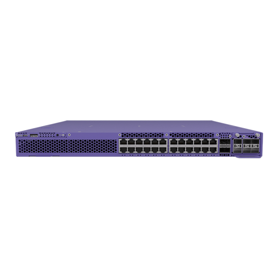
5720-48MXW Switch Features on page 16 The ExtremeSwitching 5720 Series is a family of high-performance, feature-rich edge and aggregation switches. As a universal hardware platform, the 5720 Series offers a user-selectable choice of Extreme’s flagship switch operating systems, Switch Engine and Fabric Engine. The 5720 Series includes 24- and 48-port 1/2.5/5 Multi-gig models, as well as 24- and 48-port 1/2.5/5/10 Multi-gig models. -
Page 12: Cooling
U1 and U2 ports can support data rates of 100Gb, 2 x 50Gb (Switch Engine only), 1 x 40Gb, 4 x 25Gb, or 4 x 10Gb using QSFP+ optics. Use the disable stacking-support command to set the U1 and U2 ports in Ethernet mode. ExtremeSwitching 5720 Series Hardware Installation Guide... -
Page 13: Operating Temperatures
Feature Licensing The ExtremeSwitching 5720 Series switches support Unified Licensing, so that you can use them with multiple operating systems. There are two methods of acquiring feature licenses: manual or through ExtremeCloud IQ™ (XIQ). -
Page 14: 5720-24Mxw Switch Features
1 USB A port for management or external USB flash • 1 USB Micro-B console port • 1 VIM slot (unpopulated) Figure 3: 5720-24MXW Front Panel 1 = Micro-B USB console port 4 = Mode button 6 = VIM slot ExtremeSwitching 5720 Series Hardware Installation Guide... -
Page 15: 5720-48Mw Switch Features
1 USB A port for management or external USB flash • 1 USB Micro-B console port • 1 VIM slot (unpopulated) Figure 5: 5720-48MW Front Panel 1 = Micro-B USB console port 4 = Mode button 6 = VIM slot ExtremeSwitching 5720 Series Hardware Installation Guide... -
Page 16: 5720-48Mxw Switch Features
1 USB A port for management or external USB flash • 1 USB Micro-B console port • 1 VIM slot (unpopulated) Figure 7: 5720-48MXW Front Panel 1 = Micro-B USB console port 4 = Mode button 6 = VIM slot ExtremeSwitching 5720 Series Hardware Installation Guide... - Page 17 Figure 8: 5720-48MXW Rear Panel 1 = SSD slot 3 = OOB management port 5 = Grounding lug 2 = Fan modules 4 = Power supply slots 6 = Serial console port 7 = USB 2 port ExtremeSwitching 5720 Series Hardware Installation Guide...
-
Page 18: Port Partitions
Two QSFP28 ports with one of the following: QSFP28 • One 100 Gb port • Two 50 Gb ports (on Switch Engine only) For information about configuring partitioned ports, see the Switch Engine 32.1 Command Reference Guide. ExtremeSwitching 5720 Series Hardware Installation Guide... -
Page 19: Power Supplies For Use With Your Switch
The 1100 W AC PSU-FB (model XN-ACPWR-1100W-FB with front-to-back ventilation airflow) is compatible with all 5720 Series switch models. The 1100 W AC power supply has a keyed power inlet (C16) that requires a notched (C15) power cord. ExtremeSwitching 5720 Series Hardware Installation Guide... -
Page 20: 2000 W Ac Power Supply
OUT_OK Description (Green) (Green or Red) No AC input power connection or low AC voltage. AC input good, 54V output disabled. (Red) On AC input good, output (54V) fault. (Green) On AC input good. ExtremeSwitching 5720 Series Hardware Installation Guide... -
Page 21: Expansion Modules
You can install a versatile interface module (VIM) in a dedicated slot in the front panel of the ExtremeSwitching 5720 Series switch to provide 25/100G dedicated high speed ports. The front panel of every 5720 Series switch provides one slot to install the following: •... -
Page 22: 5720-Vim-2Ce Versatile Interface Module
The 5720-VIM-2CE versatile interface module provides two 100GbE QSFP28, MACsec capable ports. Data rates of 10/25/40Gb are supported through port partitioning. For information about the supported optical modules, refer to the most recent version of the Extreme Optics website. ExtremeSwitching 5720 Series Hardware Installation Guide... -
Page 23: 5720-Vim-6Ye Versatile Interface Module
5720-VIM-6YE Versatile Interface Module The 5720-VIM-6YE versatile interface module provides six 10/25GbE SFP28, MACsec capable ports. For information about the supported optical modules, refer to the most recent version of the Extreme Optics website. ExtremeSwitching 5720 Series Hardware Installation Guide... -
Page 24: Solid-State Drives
The following SSD module is available for 5720 Series switches: Table 11: Available SSD Module SSD Module Description Compatible Switch Models XN-SSD-002-120 Modular 120GB SSD 5720-24MXW and 5720-48MXW Note An SSD module is not supported on 5720-24MW and 5720-48MW models. ExtremeSwitching 5720 Series Hardware Installation Guide... -
Page 25: Site Preparation
The physical installation site must meet the following requirements for a safe and successful installation: • Building and electrical code requirements • Environmental, safety, and thermal requirements for the equipment you plan to install • Equipment rack requirements 2. Evaluating and meeting cable requirements. ExtremeSwitching 5720 Series Hardware Installation Guide... -
Page 26: Operating Environment Requirements
Site Preparation After examining your physical site and verifying that all environment requirements are met, evaluate and compare your existing cable plant with the requirements of the Extreme Networks equipment to determine if you need to install new cables. 3. Meeting power requirements. -
Page 27: Set Up The Wiring Closet
Consult an electrical contractor for commercial building and wiring specifications. Control the Temperature Extreme Networks equipment generates a significant amount of heat. It is essential that you provide a temperature-controlled environment for both performance and safety. Install the equipment only in a temperature- and humidity-controlled indoor area that is free of airborne materials that can conduct electricity. -
Page 28: Control The Humidity Level
Table 13 summarizes the behavior of ExtremeSwitching switches when they experience high operating temperatures. Safeguards are built into all Extreme Networks switches and power supply units to minimize the risk of fire. Table 13: Thermal Shutdown and Restart Behavior Switch Model(s) -
Page 29: Rack Specifications And Recommendations
Because building codes vary worldwide, consult an electrical contractor to ensure proper equipment grounding for your specific installation. Provide Adequate Space for the Rack Provide enough space in front of and behind the switch so that you can service it easily. ExtremeSwitching 5720 Series Hardware Installation Guide... -
Page 30: Secure The Rack
Extra room on each side is optional. Warning Extreme Networks switches do not have a switch for turning power to the unit on and off. For systems using an AC power supply, power to the switch is disconnected by removing the wall plug from the electrical outlet. -
Page 31: Install Cable
Assign a unique block of sequential numbers to the group of cables that run between each pair of wiring closets. • Assign a unique identification number to each equipment rack. • Identify all wiring closets by labeling the front panel of your Extreme Networks equipment and other hardware. • Keep accurate and current cable identification records. •... - Page 32 Use care in dressing the optical fiber cables: provide satisfactory strain relief to support the cable and maintain an adequate bend radius at all cable turns, particularly where the cable connects to the I/O module. ExtremeSwitching 5720 Series Hardware Installation Guide...
- Page 33 10/125 µm single-mode fiber – 100,000 (1550nm optical window) 1 Proprietary to Extreme Networks. Connections between two Extreme Networks 1000BASE-LX interfaces that use 10/125 µm single-mode fiber can use a maximum distance of 10,000 meters. ExtremeSwitching 5720 Series Hardware Installation Guide...
-
Page 34: Use Rj45 Connector Jackets
Connectors that are not properly aligned with the port. • Crowded cable installation, which can cause connectors to pop out of the port. Figure 15 shows examples of recommended and non-recommended connector jacket types. ExtremeSwitching 5720 Series Hardware Installation Guide... -
Page 35: Prevent Radio Frequency Interference (Rfi)
Requirements for PoE Devices When connecting PoE devices to a PoE switch, all connections between the PoE device and the switch must remain within the same building and use a low-voltage power distribution system per IEEE 802.3af. ExtremeSwitching 5720 Series Hardware Installation Guide... -
Page 36: Power Supply Requirements
Extreme Networks equipment. The web page provides specifications for power cords in each country so that you can purchase cords locally. UPS (Uninterruptible Power Supply) Requirements... -
Page 37: Follow Applicable Industry Standards
UPS transfer time. UPS transition times vary between UPS models and implementations, but shorter transition times are preferred. For Extreme Networks stacking products, a UPS transition time of 20 milliseconds or less ensures optimum performance and minimizes service interruptions. - Page 38 For more information, see the following ANSI/TIA/EIA standards: • ANSI/TIA/EIA-568-A—the six subsystems of a structured cabling system • ANSI/TIA/EIA-569-A—design considerations • ANSI/TIA/EIA-606—cabling system administration • ANSI/TIA/EIA-607—commercial building grounding and bonding requirements You can access these standards at: www.ansi.org or www.tiaonline.org. ExtremeSwitching 5720 Series Hardware Installation Guide...
-
Page 39: Build Stacks
SummitStack cables. All connections between stack ports must be directly between switches. A stacking connection cannot pass through a third device, for example a Virtual Port Extender or an LRM/MACsec Adapter. ExtremeSwitching 5720 Series Hardware Installation Guide... -
Page 40: Build Basic Stacks
5720 Series switches do not support alternate stacking. Only native stacking is supported on 5720 Series switches. When planning and building your stack, be sure to follow port compatibility and cabling recommendations as described in this chapter. ExtremeSwitching 5720 Series Hardware Installation Guide... - Page 41 2. ExtremeSwitching 5520 For example, in a stack that combines 5720 series switches with 5520 series switches, a 5720 series switch might provide more memory and more features than the 5520 series switches in the stack. ExtremeSwitching 5720 Series Hardware Installation Guide...
-
Page 42: Summitstack Topologies
The maximum cable length supported between switches depends on the types of switches in your stack, the installed option cards, and the configured stacking ports. For more information, see Plan to Create Your Stack on page 47. ExtremeSwitching 5720 Series Hardware Installation Guide... - Page 43 To complete the ring, a longer cable connects Switch 1 with Switch 8. Figure 20: Switches Connected to Each Other in a Ring Topology ExtremeSwitching 5720 Series Hardware Installation Guide...
- Page 44 If you are using a daisy chain topology, the possibility of a dual primary condition increases. Before you create a daisy chain topology, read "Managing a Dual Primary Situation" in the Switch Engine 32.1 User Guide. ExtremeSwitching 5720 Series Hardware Installation Guide...
-
Page 45: Summitstack Terms
It can also forward data traffic. Only an active node can appear as a card inserted into a slot when the show slot {slot {detail} | detail } command is executed on the primary node of the stack. ExtremeSwitching 5720 Series Hardware Installation Guide... - Page 46 Such ports can be members of a user-configured VLAN or trunk group. They can be used for Layer 2 and 3 forwarding of user data traffic, for mirroring, or other features you can configure. Data ports are different from stacking ports. ExtremeSwitching 5720 Series Hardware Installation Guide...
-
Page 47: Plan To Create Your Stack
(VIMs), and cables – and the stacking protocols you will use. Included are: • Guidelines and other information for each switch model in your stack • Considerations for combining different switch models in a stack • Information about stacking cables ExtremeSwitching 5720 Series Hardware Installation Guide... -
Page 48: Enable And Disable The Stacking-Support Option
Recommendations for Configuring Stacks on page 49 to configure the software for your stack. The recommended procedures for installing and interconnecting a stack are found in Set up the Physical Stack on page 51. ExtremeSwitching 5720 Series Hardware Installation Guide... -
Page 49: Recommendations For Configuring Stacks
V400), or they can be stacked with ExtremeSwitching 5520 series switches using Native V200 stacking (SummitStack-V200). When creating a mixed stack of 5720 series and 5520 series switches, the Primary and Backup nodes must be 5720 series switches and they must be configured for Native V200 stacking. ExtremeSwitching 5720 Series Hardware Installation Guide... -
Page 50: Select Stacking Cables
Build Stacks Select Stacking Cables Stacking connections using the native stacking ports require stacking cables that are specific to the type of stacking port. These cables are available from Extreme Networks in lengths from 0.5 meter to 100 meters. Note... -
Page 51: Set Up The Physical Stack
After you have installed the individual switches, connect them together using the stacking cables. The examples in this section show cable connections and the recommended order for connecting ports to facilitate the easy setup configuration. ExtremeSwitching 5720 Series Hardware Installation Guide... - Page 52 Stack Port 2 Slot 1 Stack Port 1 Example: Basic Stack with Eight Switches Figure 24 shows cable connections for an 8-node stack using SummitStack 40G cables to connect switches with integrated SummitStack ports. ExtremeSwitching 5720 Series Hardware Installation Guide...
- Page 53 Port 2 on one switch is connected to Port 1 on the next connected switch. If the easy setup feature is used to configure the stack parameters, the assigned slot numbers will be as shown in the figure. ExtremeSwitching 5720 Series Hardware Installation Guide...
-
Page 54: Connect Your Stack To The Management Network
IP address configuration that will enable you to log in directly to each switch in the stack through its Ethernet management port. See the Switch Engine 32.1 User Guide for instructions to perform the software configuration for your stack. ExtremeSwitching 5720 Series Hardware Installation Guide... -
Page 55: Install Your Switch
Connect Network Interface Cables on page 66 Turn on the Switch on page 67 Before you attempt to install or remove an Extreme Networks switch, read the precautions in Safety Considerations for Installation on page 56. Extreme Networks switches fit into standard 19-inch equipment racks. -
Page 56: Safety Considerations For Installation
25, and ensure that you have the appropriate people and tools on hand. Installing Extreme Networks switches is easiest when there are two people to maneuver the switch and attach mounting hardware. Provide enough space in front of and behind the switch so that you can service it easily. Ensure that a minimum of 122 cm (48 in) in front of the rack and 76 cm (30 in) behind the rack. -
Page 57: Four-Post Rack Mount
Note which direction the sliding rails slide from the outer rails for correct installation. Figure 26: Separating the Inner Sliding Rails by Pulling the Disconnect Latch 2. Attach the outer rail (bracket) to the rack, securing it with the M5 screws. ExtremeSwitching 5720 Series Hardware Installation Guide... - Page 58 To install the switch in the front of the rack, attach a mounting bracket (ear) to a side of the switch, using #6-32 screws, so that the mounting ear is flush with the front of the rack. ExtremeSwitching 5720 Series Hardware Installation Guide...
- Page 59 6. Insert the switch into the rail kit. To install the switch in the front of the rack, slide the switch into the outer rails in the front of the rack. ExtremeSwitching 5720 Series Hardware Installation Guide...
-
Page 60: Two-Post Rack Mount
Secure the switch to the rack using the thumb screws on the mounting ears. Figure 33: Secure the Switch with Thumb Screws Two-Post Rack Mount You can attach your switch to a two-post rack in either of two configurations: • Front mount ExtremeSwitching 5720 Series Hardware Installation Guide... - Page 61 Figure 34: Attaching a Short Mounting Bracket (Ear): Front of Switch b. For a mid-mount, position the bracket so that the flange (ear) is positioned slightly more than halfway between the front and back of the switch, as shown in figure below: Figure ExtremeSwitching 5720 Series Hardware Installation Guide...
- Page 62 Position the long bracket over the holes between the front and the middle of the switch. Orient it so that its flange (ear) rests against the rack post. Figure 36 Figure Figure 36: Attaching a Long Mounting Bracket: Front of Switch ExtremeSwitching 5720 Series Hardware Installation Guide...
- Page 63 6. Secure the flanges (ears) on both sides of the switch to the rack posts, using screws that are appropriate for the rack. (Rack-mounting screws are not provided.) Figure 38 Figure 39 for the completed installations. ExtremeSwitching 5720 Series Hardware Installation Guide...
- Page 64 Two-Post Rack Mount Install Your Switch Figure 38: Two-Post Front Mount: Complete ExtremeSwitching 5720 Series Hardware Installation Guide...
-
Page 65: Install Optional Components
ExtremeSwitching switches support the use of pluggable transceivers and cables in the SFP+, SFP28, QSFP+, and QSFP28 formats. For a list of the optical components supported with ExtremeSwitching devices, see the Extreme Optics website. ExtremeSwitching 5720 Series Hardware Installation Guide... -
Page 66: Pluggable Transceiver Modules
Pluggable Transceiver Modules Install Your Switch Pluggable Transceiver Modules Extreme Networks offers several optical transceiver modules for transmitting and receiving data over optical fiber rather than through electrical wires. Note A small flat-blade screwdriver can be used to free an obstructed bale clasp on an optical module. -
Page 67: Turn On The Switch
An AC power cord is not included with the AC power supply. You can purchase AC power cords for use in the US and Canada from Extreme Networks or from your local supplier. The cord must meet the requirements listed in Power Cord Requirements for AC-Powered Switches and AC Power Supplies page 98. -
Page 68: Activate And Verify The Switch
Switch Engine is the default operating system for the 5720 Series. If you want to run Fabric Engine, see Change the Switch OS via the Bootloader Menu on page 70 or Change the Switch OS via the Startup Menu on page 70. ExtremeSwitching 5720 Series Hardware Installation Guide... -
Page 69: Configure The Switch's Ip Address For The Management Vlan
Configure the Switch's IP Address for the Management VLAN You can configure the switch's IP address for the management virtual LAN (VLAN). Note The management port is part of the mgmt VLAN. This VLAN membership cannot be changed. ExtremeSwitching 5720 Series Hardware Installation Guide... -
Page 70: Change The Switch Os Via The Bootloader Menu
Change the Switch OS via the Startup Menu Onboard your switch with Switch Engine™. Log in or create your XIQ administrator account in order to select your switch operating system with XIQ at https://extremecloudiq.com. ExtremeSwitching 5720 Series Hardware Installation Guide... -
Page 71: Log In For The First Time On Fabric Engine
When prompted for the password, enter rwa. When you are logged in with the role-based authentical level of rwa, you can configure the login and password values for the other role-based authentication levels. ExtremeSwitching 5720 Series Hardware Installation Guide... -
Page 72: Install Expansion Modules
• Flat head screwdriver Caution Extreme Networks VIMs are not hot-swappable. Disconnect power to the switch before removing an installed VIM or installing a new VIM. To install a versatile interface module, follow these steps: 1. Attach the ESD wrist strap to your wrist and connect the metal end to an appropriate ground point on the rack. -
Page 73: Install An Ssd Module
This topic describes how to install a Solid-State Drive (SSD) module in the rear slot of the 24MXW and 48MXW switch models. You need the following tools and materials to install an SSD module: • ESD-preventive wrist strap ExtremeSwitching 5720 Series Hardware Installation Guide... - Page 74 5. Carefully slide the SSD module into the slot on the rear panel until it is firmly in place. 6. Secure the SSD module using the screw provided. Figure 43: SSD Module Inserted in Slot 1 = SSD module retaining screw location ExtremeSwitching 5720 Series Hardware Installation Guide...
-
Page 75: Replace Internal Ac Power Supplies
2. Note the orientation of the installed power supply, and the location of the latching tab at the left of the unit. 3. Push the latching tab toward the power supply handle and pull outward on the handle to disengage the power supply internal connectors. See Figure ExtremeSwitching 5720 Series Hardware Installation Guide... - Page 76 5. Verify that the replacement power supply is oriented the same way as the unit you removed, and has the same airflow direction. 6. Carefully slide the power supply all the way into the power supply bay, as shown in Figure ExtremeSwitching 5720 Series Hardware Installation Guide...
-
Page 77: Replace An 1100 W Ac Power Supply
You need the following tools and materials to replace an 1100 W AC power supply: • Thermal protective gloves • AC power cord, if you will not be re-using the cord from the removed power supply ExtremeSwitching 5720 Series Hardware Installation Guide... - Page 78 5. Verify that the replacement power supply is oriented the same way as the unit you removed, and has the same airflow direction. 6. Carefully slide the power supply all the way into the power supply bay, as shown in Figure ExtremeSwitching 5720 Series Hardware Installation Guide...
-
Page 79: Replace A 2000 W Ac Power Supply
You need the following tools and materials to replace a 2000 W AC power supply: • Thermal protective gloves • AC power cord, if you will not be re-using the cord from the removed power supply ExtremeSwitching 5720 Series Hardware Installation Guide... - Page 80 5. Verify that the replacement power supply is oriented the same way as the unit you removed, and has the same airflow direction. 6. Carefully slide the power supply all the way into the power supply bay, as shown in Figure ExtremeSwitching 5720 Series Hardware Installation Guide...
- Page 81 Always be sure that the source outlet is properly grounded before plugging the AC power cord into the AC power supply. 9. If the power supply is equipped with a power cord retainer, use the retainer to secure the power cord to the power supply. ExtremeSwitching 5720 Series Hardware Installation Guide...
-
Page 82: Replace Fan Modules
5720 Series switches are available with front-to-back airflow. In this switch, the fan modules are labled Air Out. All installed fan modules must blow air in the same direction and must match the airflow direction of the installed power supplies. ExtremeSwitching 5720 Series Hardware Installation Guide... -
Page 83: Replace A Fan Module
Unoccupied slots must always be covered to maintain proper system ventilation. 3. Verify that the airflow direction on the replacement fan module matches that of the installed fan modules. Fans with front-to-back airflow are labeled Air Out. ExtremeSwitching 5720 Series Hardware Installation Guide... - Page 84 4. Carefully slide the replacement fan module all the way into the fan module slot, as shown in Figure Figure 51: Installing a Fan Module 5. Push the fan module in until the latch snaps into place. Caution Do not slam the fan module into the switch. ExtremeSwitching 5720 Series Hardware Installation Guide...
-
Page 85: Replace A Versatile Interface Module Or Solid-State Drive
2. Disconnect the switch power. 3. Remove the existing VIM or SSD: a. Remove the retaining screws holding the existing module in place. Figure 52: SSD Module Inserted in Slot ExtremeSwitching 5720 Series Hardware Installation Guide... - Page 86 Carefully slide the module into the switch. b. Insert and tighten the retaining screws you removed in step 3.a. Figure 54: Tighten Screws to Secure the VIM Module Figure 55: Tighten Screw to Secure the SSD Module ExtremeSwitching 5720 Series Hardware Installation Guide...
-
Page 87: Monitor The Device
87 The following topics help you monitor the status of the 5720 Series while it is operating. 5720 Series LEDs ExtremeSwitching 5720 Series Front Panel LEDs, as described in the following table: Table 20: 5720 Series Port LEDs Color/State... -
Page 88: Port Leds In Default (Sys) Mode
Color and blink pattern indicate speeds, as referenced by the following table: Table 22: Port LEDs in SPD Mode Color/State Speed (RJ45, SFP) Speed (QSFP) Steady green unused 100Gbps Blinking green 100Mbps 50Gbps Steady amber 1000Mbps 40Gbps Slow blinking amber 2.5Gbps 25Gbps ExtremeSwitching 5720 Series Hardware Installation Guide... -
Page 89: Port Leds In Stk Mode
State Blinking Green Packet transmitting or receiving No packet transmitting or receiving Locator LED The blue LED labelled LOC on the front panel is the locator LED, which is controlled by using the CLI. ExtremeSwitching 5720 Series Hardware Installation Guide... -
Page 90: Technical Specifications
99 This section lists technical specifications for the hardware products described in this document. The 5720 Series includes the following switches: • 5720-24MW switch • 5720-24MXW switch • 5720-48MW switch • 5720-48MXW switch ExtremeSwitching 5720 Series Hardware Installation Guide... -
Page 91: Extremeswitching 5720 Series Technical Specifications
0.78 lb (0.35 kg) Height: 2.48 inches (6.3 cm) Width: 4.1 inches (10.4 cm) 5720-VIM-6YE 0.83 lb (0.38 kg) Length: 8.97 inches (22.78 cm) Fan and Acoustic Noise Refer to the 5720 Data Sheet for up-to-date information. ExtremeSwitching 5720 Series Hardware Installation Guide... -
Page 92: Fan Speed And Temperature Variation
* Some units are equipped with (3) fan modules, while others are equipped with 4. Total fan power is equal to the number of installed fan modules multiplied by the fan power for each module. Power Options ExtremeSwitching 5720 Series Hardware Installation Guide... -
Page 93: Mean Time Between Failures (Mtbf)
3,000 meters when using 5720 models with the 715W power supply. Refer to the 5720 Data Sheet for additional PSUs information. Mean Time Between Failures (MTBF) Table 33: 5720 MTBF Ambient Temp = 5720-24MW 5720-24MXW 5720-48MW 5720-48MXW 25°C System base 460,603 351,532 417,583 325,908 ExtremeSwitching 5720 Series Hardware Installation Guide... -
Page 94: Cpu And Memory
FCC CFR 47 part 15 Class A (USA) ICES-003 Class A (Canada) European EMC standards EN 55032 Class A EN 55024, EN 55035 EN 61000-3-2,2014 (Harmonics) EN 61000-3-3,2013 (Flicker) EN 300 386 (EMC Telecommunications) 2014/30/EU EMC Directive ExtremeSwitching 5720 Series Hardware Installation Guide... - Page 95 EN/ETSI 300 753 (1997-10) - Acoustic Noise ASTM D3580 Random Vibration Unpackaged 1.5G Environmental compliance EU RoHS - 2011/65/EU EU WEEE - 2012/19/EU EU REACH – Regulation (EC) No 1907/2006 Reporting China RoHS - SJ/T 11363-2006 ExtremeSwitching 5720 Series Hardware Installation Guide...
-
Page 96: 715 W Ac Power Supplies Technical Specifications
Power Cord Requirements for AC-Powered Switches and AC Power Supplies on page 98 Efficiency Minimum efficiency: 88% at maximum power output Table 42: Environmental Specifications Operating temperature -10°C to 50°C (normal operation) Storage temperature -40°C to 70°C ExtremeSwitching 5720 Series Hardware Installation Guide... -
Page 97: 1100 W Ac Power Supplies Technical Specifications
Minimum efficiency: 88% at maximum power output Table 45: Environmental Specifications Operating temperature 0°C to 50°C (normal operation) Storage temperature -40°C to 70°C Operating humidity 93% relative humidity, non-condensing at 30C 30 m/s 2 (3 G) Operational shock ExtremeSwitching 5720 Series Hardware Installation Guide... -
Page 98: 2000 W Ac Power Supply Technical Specifications
-40°C to 70°C Operating humidity 93% relative humidity, non-condensing at 30C Operational shock Power Cord Requirements for AC-Powered Switches and AC Power Supplies An AC power cord is not included with the AC power supply. ExtremeSwitching 5720 Series Hardware Installation Guide... -
Page 99: Console Connector Pinouts
TXD (transmit data) DTR (data terminal ready) GND (ground) DSR (data set ready) RTS (request to send) CTS (clear to send) Figure 57 shows the pinouts for a 9-pin to 25-pin (RS-232) null-modem cable. ExtremeSwitching 5720 Series Hardware Installation Guide... - Page 100 RJ45 console port on the ExtremeSwitching switches. Table 50: RJ45 Console Port on Switch Function Pin Number Direction RTS (request to send) DTR (data carrier detect) TXD (transmit data) GND (ground) — GND (ground) — ExtremeSwitching 5720 Series Hardware Installation Guide...
- Page 101 Table 51: Pinouts for an RJ45 to DB-9 Adapter Signal RJ45 Pin DB-9 Pin CTS (clear to send) DTR (data carrier detect) TXD (transmit data) GND (ground) GND (ground) RXD (receive data) DSR (data set ready) RTS (request to send) ExtremeSwitching 5720 Series Hardware Installation Guide...
-
Page 102: Safety And Regulatory Information
Only trained and qualified service personnel (as defined in IEC 60950-1 and AS/NZS 3260) should install, replace, or perform service to Extreme Networks switches and their components. Qualified personnel have read all related installation manuals, have the technical training and experience necessary to be aware of the hazards to which they are exposed in performing a task, and are aware of measures to minimize the danger to themselves or other persons. -
Page 103: General Safety Precautions
Make sure that your power supplies meet the site DC power or AC power requirements of all the network equipment. • Racks for Extreme Networks equipment must be permanently attached to the floor. Failure to stabilize the rack can cause the rack to tip over when the equipment is removed for servicing. •... -
Page 104: Maintenance Safety
Install all cables in a manner that avoids strain. Use tie wraps or other strain relief devices. Fiber Optic Ports and Optical Safety The following safety warnings apply to all optical devices used in Extreme Networks equipment that are removable or directly installed in an I/O module or chassis system. -
Page 105: Gbic, Sfp (Mini-Gbic), Qsfp+, Xenpak, And Xfp Regulatory Compliance
GBIC, SFP (Mini-GBIC), QSFP+, XENPAK, and XFP Safety and Regulatory Information Regulatory Compliance GBIC, SFP (Mini-GBIC), QSFP+, XENPAK, and XFP Regulatory Compliance Extreme Networks pluggable optical modules and direct-attach cables meet the following regulatory requirements: • Class 1 or Class 1M Laser Product •... -
Page 106: Install Power Supply Units And Connect Power
When you install DC power supplies or connect DC power: • Extreme Networks DC power supplies do not have switches for turning the unit on and off. Make sure that the DC circuit is de-energized before connecting or disconnecting the DC power cord at the DC input power socket. -
Page 107: Battery Notice
Il y a risque d’explosion si la pile est remplacée par un type de pile incorrect. Éliminez les piles usées en conformité aux règlements locaux d'élimination des piles. Battery Warning - Taiwan ExtremeSwitching 5720 Series Hardware Installation Guide... -
Page 108: Emc Warnings
This is a Class A product based on the standard of the VCCI Council. If this equipment is used in a domestic environment, radio interference may occur, in which case the user may be required to take corrective actions. Korea EMC Statement ExtremeSwitching 5720 Series Hardware Installation Guide... - Page 109 IP address 69 airflow 82 VLAN 69 alternate stacking 45 configuring the switch 71 amperage connecting calculating for UPS 37 to management console 68 announcements 9, 10 connecting power 67 ANSI standards 37 connector jackets RJ45 34 connector pinouts DB-9 console connector 99 ExtremeSwitching 5720 Series Hardware Installation Guide...
- Page 110 Index connector pinouts (continued) null-modem cable 99 discharge from cable 31 console port system protection 28 5720 series 11–13 expansion modules for stacked configurations 54 install 72 on switch 99 Extreme Stacking Tool 50 settings 68 control path 45 conventions Fabric Engine notice icons 7 initial login 71 text 7 failover 47 cooling 82 cords airflow 82 requirements 98 replacing 82, 83...
- Page 111 Index IP settings pinouts (continued) configuring 69 DB-9 console connector 99 null-modem cable 99 planning site 25 jackets plenum-rated cable 31 RJ45 connector 34 pluggable transceivers, see optical transceivers port partitions 18 port option cards labeling cables 30 types 21 LEDs ports 5720 Series 87–89 console port settings 68 stack number indicator 41 for stacked configurations 54 local management connection 68 management 68...
- Page 112 Index radio frequency interference (RFI) (continued) stacking (continued) preventing 35 definition 40 redundancy dual primary condition 44 in a stack 41 examples 52, 53 regulatory information 102 guidelines 48, 49 removing LEDs 41 1100 W AC power supply 77 multiple-rack 53 2000 W AC power supply 79 native stacking ports 40 715 W AC power supply 75 primary 41 fan module 83 priority 41...
- Page 113 Index unshielded twisted pair, see UTP cable UPS (uninterruptible power supply) requirements 36 selecting 37 transition time 37 UTP cable bend radius 31 category 5 31 discharge ESD 31 preventing RFI 35 versatile interface module (VIM) 5720-VIM-2CE 22 5720-VIM-6YE 23 installing 72 replacing 85 types 21 VLAN configuring 69 warnings 7 web app SummitStack 50 wiring closet electrostatic discharge (ESD) 28 floor coverings 27...
Need help?
Do you have a question about the ExtremeSwitching 5720 Series and is the answer not in the manual?
Questions and answers