Table of Contents
Advertisement
Quick Links
Advertisement
Table of Contents

Related Manuals for Mellanox Technologies SwitchX-2 MSX6005F-1BFS


Summary of Contents for Mellanox Technologies SwitchX-2 MSX6005F-1BFS
- Page 1 SwitchX®-2 12 Port InfiniBand Switch System Hardware User Manual P/N: MSX6005F-1BFS, MSX6005T-1BFS, MSX6012F-1BFS, MSX6012F-2BFS, MSX6012T-1BFS, MSX6012T-2BFS, MSX6005F-1BRS, MSX6005T-1BRS, MSX6012F-1BRS, MSX6012T-1BRS Rev 1.0 www.mellanox.com...
- Page 2 KIND AND SOLELY FOR THE PURPOSE OF AIDING THE CUSTOMER IN TESTING APPLICATIONS THAT USE THE PRODUCTS IN DESIGNATED SOLUTIONS. THE CUSTOMER'S MANUFACTURING TEST ENVIRONMENT HAS NOT MET THE STANDARDS SET BY MELLANOX TECHNOLOGIES TO FULLY QUALIFY THE PRODUCTO(S) AND/OR THE SYSTEM USING IT. THEREFORE, MELLANOX TECHNOLOGIES CANNOT AND DOES NOT GUARANTEE OR WARRANT THAT THE PRODUCTS WILL OPERATE WITH THE HIGHEST QUALITY.
-
Page 3: Table Of Contents
5.4 Updating Firmware Internally Managed Switch ......51 5.5 Updating Firmware Externally Managed Switch ......51 Mellanox Technologies... - Page 4 Appendix L 安裝安全性警告 (Chinese) ........88 Mellanox Technologies...
-
Page 5: List Of Figures
Figure 32: QSFP Connector Male and Female Views ........60 Mellanox Technologies... -
Page 6: List Of Tables
OPNs for Replacement Parts ..........62 Mellanox Technologies... -
Page 7: Revision History
SwitchX®-2 12 Port InfiniBand Switch System Hardware User Manual Rev 1.0 Revision History Table 1 - Revision History Table Date Revision Description July 2013 Initial Draft Mellanox Technologies... -
Page 8: About This Manual
This requires a customer support login. Look up the relevant SwitchX®- based switch system/series release note file. This document contains information regarding configuring and manag- Mellanox MLNX-OS® Software User ing Mellanox Technologies Switch Platforms. Manual Command Reference Guide for MLNX-OS® listing all of the commands MLNX-OS® Software Command Ref- available through MLNX-OS®... -
Page 9: Abbreviations
This icon indicates a situation that can potentially cause damage to hardware or soft- ware. BEWARE! This icon indicates a situation that can potentially cause personal injury or damage to hardware or software. Abbreviations FDR — Fourteen Data Rate – Used to indicate a 4X port running at 56 Gb/s. Mellanox Technologies... -
Page 10: Mellanox Part Numbering Legend
Rev 1.0 Mellanox Part Numbering Legend Place Field Decoder Mellanox Technologies System Type SwitchX® switch Family Data Transfer Protocol 6 = InfiniBand Size of box 0 = 1U 1 = 1.5U 2 = 2U Management Capabilities 05 = 12 Ports externally managed... -
Page 11: Chapter 1 Overview
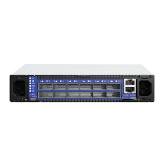
See Section 5 on page 50 for more information. Installation, hot-swapping components and hardware maintenance is covered in “Basic Opera- tion” on page 16. Figure 1: Internally Managed Switch SX6012 Mellanox SX6012 Figure 2: Externally Managed Switch SX6005 Mellanox SX6005 Mellanox Technologies... -
Page 12: Features
• Congestion control** • Adaptive routing** • Port mirroring** • Forward Error Correction -(FEC) • Link Layer Retransmission -(LLR) • Multiple SWIDs ** * License required. ** This feature will be available to customers in the near future. Mellanox Technologies... -
Page 13: Table 4: Management Software
Network Management Inter- • SNMP v1,v2c,v3 faces • REST interfaces (XML Gateway) Security • • Telnet • RADIUS • TACACS+ Date and Time • Cables & Transceivers • Transceiver info Virtual Port Interconnect® • Ethernet (VPI) • InfiniBand Mellanox Technologies... -
Page 14: Serial Number And Product Version Information
Both FDR and FDR10 support Forward Error Correction (FEC), as described in IEEE 802.3ap chapter 74. FDR and FDR10 are only guaranteed to work with approved Mellanox Cables. FDR10 is only guaranteed to work with approved Mellanox ConnectX®-3 adapters. Mellanox Technologies... -
Page 15: Internally Managed Vs. Externally Managed
RS232 cable DB9 to RJ-45 included in the box to connect to host PC for ini- Managed tial configuration of the switch. After initial configuration, the switch can be managed through the Ethernet port using a remote connection. Mellanox Technologies... -
Page 16: Chapter 2 Basic Operation
Figure 5: Switch System Connector Side Panels Mellanox SX6012 Status LEDs The System Status LEDs are located to the left of the connectors on the connector side panel. 2.2.1 System Status LEDs Figure 6: Externally Managed System Status LEDS Mellanox SX6005 Mellanox Technologies... -
Page 17: Table 6: System Status Leds
For more information See page 53. If the PS LEDs are not green, this indicates a problem with the power supplies. The switch is operational only if at least one of the PS LEDs is green. Mellanox Technologies... -
Page 18: Figure 7: Switch Status Led
All fans must be operating while the power supply is plugged in. switch switch If the shuts down due to over temperature, unplug the , wait 5 minutes switch See page 53 and replug in the . For more information Mellanox Technologies... -
Page 19: Figure 8: Fan Status Led Connector Side
Error – One or more fans is not operating properly. The system should be powered down and troubleshoot the fan module. For the SX6005 replace the switch. Off – The fan unit is not receiving any power. Check that the fan unit is properly and completely inserted. Mellanox Technologies... -
Page 20: Figure 9: Power Status Led Connector Side
Error – The PS unit is not operational. Off – There is no power to the system (neither PS unit is receiving power). If one PS unit is showing green and the second PS unit is unplugged it will show a red indication. Mellanox Technologies... -
Page 21: Figure 10: Bad Port Led
The UID LED is a debug feature that lights a blue LED on the switch connector side panel for ease in finding a particular switch within a cluster. 1. This feature will be available in a coming software release. Mellanox Technologies... -
Page 22: Port Connector Leds
Table 11 - Port Connector Physical and Logical Link Assignments for Ethernet Mode LED Configuration LED Description Physical link is down / Default. Solid Green Physical link is up with no traffic. Flashing Green Physical link is up with traffic. Flashing Orange Physical errors. Mellanox Technologies... -
Page 23: Air Flow
• 1 – USB port that is labeled This interface can be used to update software or firmware. This is only on the managed switch. • 1 – connector that is labeled Use this connector to connect to the host PC. Mellanox Technologies... -
Page 24: Figure 13: Front Side Interfaces For The Internally Managed Switch
The Ethernet connection labeled provides access for remote management. The switch can be connected to any Ethernet port. The Ethernet port on the connector side of the switch is mgmt0. These connector(s) are not found in unmanaged (externally managed) switches. Mellanox Technologies... - Page 25 This connector can be used to install firmware upgrades, should the and Troubleshooting only. firmware image be damaged and cannot be upgraded through a host PC or remotely. This inter- face is for support personnel and advanced users only. Mellanox Technologies...
-
Page 26: Figure 15: Rear Of Switch
On the connector side panel under the system LEDs is a reset button . This reset button requires a tool to be pressed. DO NOT use a sharp pointed object such as needle or push pin for pressing the Reset button. Sharp objects can cause damage, use a flat object to push the reset button. Mellanox Technologies... -
Page 27: Figure 16: Reset Button
The ports are labelled as shown in Figure 17. The bottom row ports are flipped from the top row. See Figure 18 for bottom row - top row port orientation. See page 48 for more information regarding breakout (fanout) cables. Figure 17: Port Numbering Figure 18: Top and Bottom QSFP Port Orientation Mellanox Technologies... -
Page 28: Chapter 3 Installation
“Avertismente privind siguranţa la instalare (Romanian)” on page 83, and for Chinese see page 88. 1. Installation Instructions Read all installation instructions before connecting the equipment to the power source. 2. Installation in Restricted Access Location This unit is intended for installation in a Restricted Access Location. Mellanox Technologies... - Page 29 When this product is mounted or serviced in a rack, special precautions must be taken to ensure that the system remains stable. In general you should fill the rack with equipment starting from the bottom to the top. Mellanox Technologies...
- Page 30 “<HAR>”, 3 - conductor, minimum 1.0 mm wire, rated at 300 V, with a PVC insulated jacket. The cord must have a molded plug rated at 250 V, 10 A. 16. High Leakage Current Warning: High leakage current; Earth connection essential before connecting supply. Mellanox Technologies...
- Page 31 Caution: Slide/rail mounted equipment is not to be used as a shelf or a work space. The rails are not intended for sliding the unit away from the rack. It is for permanent installation at final resting place only, not used for service and maintenance Mellanox Technologies...
-
Page 32: Package Contents
Norway only. 3.1.1 Battery Replacement Mellanox Technologies does not support battery replacement. Customer removal of the switch cover will void the warrantee. Only Remove the cover to comply with WEEE directives or to dis- assemble for environmentally approved disposal. Customer removal of the switch cover will void the warrantee. -
Page 33: Mechanical Installation
1. Peel and stick the four rubber bumpers into the bottom of the switch. Place them in the round circles. Figure 19: Placing the Bumpers Bottom of the switch 2. Place on a flat surface. Make sure the switch sits solid on the surface. Mellanox Technologies... -
Page 34: Figure 20: Installation Kit Parts For A Side By Side Installation
1. Place the ESD mat on the floor where you will be working and put on the ESD strap. Make sure the ESD strap is touching your skin and that the other end is connected to a verified ground. 2. Screw the two switch mounted rails to the switch using six flat head screws per rail. Mellanox Technologies... -
Page 35: Figure 21: Screw On The Switch Mounted Rails
SwitchX®-2 12 Port InfiniBand Switch System Hardware User Manual Rev 1.0 Figure 21: Screw on the Switch Mounted Rails Install the two switch frame into the rack. 1. Slide the Frame slides into the frame. Mellanox Technologies... -
Page 36: Figure 22: Two Switch Frame
2. Place the frame in the rack. Both sides of the frame need to be on the inside of the rack. Figure 23: Placement of Frame in the Rack 3. Take the 10 spacer bushings and use them to adapt the square openings in the vertical support. Mellanox Technologies... -
Page 37: Figure 24: Placing The Spacer In The Rack
4. Use the 10 M5 pan head screws. Do not tighten the screws for the frame. Figure 25: Using the Spacer Bushings 5. Slide the switch into the frame, and screw in the capture bolts into the frame. Mellanox Technologies... -
Page 38: Figure 26: Insert Switch Into Frame
Anytime the switch is powered down (by choice or by power failure) you must unplug the 2 PSUs before powering up the system. 12. You can start connecting all of the cables to the switch. Mellanox Technologies... -
Page 39: Grounding The Switch
15A or higher. Caution: The switch platform will automatically power on when AC power is applied. There is no power switch. Check all boards, power supplies, and fan tray modules for proper insertion before plugging in a power cable. Mellanox Technologies... -
Page 40: Externally Managed Switches
The externally managed switches are Plug and Play and all firmware updates should be done in- band. The I2C connection should only be used if the firmware image was corrupted to the point that the regular firmware tools cannot successfully reburn the correct image. Mellanox Technologies... -
Page 41: Internally Managed Switch Configuration
This must be done before any remote management is available. Hook up the supplied harness cable (HAR00028) from the connector labelled to the DB9 connector of the local host PC. Figure 29: Console Port Connect the host PC to this port. Mellanox Technologies... -
Page 42: Table 13: Serial Terminal Program Configuration
Type ‘y’ for initial configuration? yes and then press <Enter>. Step 1: Hostname? [switch] If you wish to accept the default hostname, then press <Enter>. Otherwise, type a different hostname and press <Enter>. Mellanox Technologies... - Page 43 Note: <enter> to save changes and exit. To re-run the configuration wizard run the command Choice: <Enter> “configuration jump-start” in Config mode. Configuration changes saved. The table below shows an example of static IP configuration for mgmt0 interface. Mellanox Technologies...
-
Page 44: Table 15: Configuration Wizard Session - Static Ip Configuration
To change an answer, enter the step number to return to. Otherwise hit <enter> to save changes and exit. Choice: Configuration changes saved. To return to the wizard from the CLI, enter the “configuration jump-start” command from configure mode. Launching CLI... switch> Mellanox Technologies... -
Page 45: Table 16: Configuration Wizard Session - Zeroconf Configuration
The following is an example of the output: Interface mgmt0 state Admin up: Link up: IP address: 192.168.10.43 Netmask: 255.255.255.0 Speed: 1000Mb/s (auto) Duplex: full (auto) Interface type: ethernet Interface source: physical MTU: 1500 HW address: 00:02:C9:11:2A:AE Comment: Mellanox Technologies... - Page 46 To Start an SSH Connection to the Switch perform the following steps: 1. Set up an Ethernet connection between the switch and a local network machine (“the remote machine” henceforth) using a standard RJ-45 connector. 2. Connect to the remote machine (rem_mach1 is used as an example). Mellanox Technologies...
- Page 47 <switch_IP_address> is the IP address of the switch. rem_mach1 > ssh -l <username> <switch ip address> Mellanox MLNX-OS® Switch Management Password: Last login: March 13, 2013 from 192.168.10.1 Mellanox Switch switch > 4. You can enter any supported command now. Mellanox Technologies...
-
Page 48: Chapter 4 Cabling
40 GbE port into 4 lanes (4 SFP+ connectors 10 GbE each). All ports can also split into 2 10 GbE ports, using lanes 1 and 2 only. When a QSFP port is split into 2 10 GbE ports then only SFP+ connectors #1 and #2 are used. Connectors #3 and #4 are left unconnected. Mellanox Technologies... -
Page 49: Figure 31: Breakout Or Fanout Cable
Figure 31: Breakout or Fanout Cable When using this feature you MUST go into the MLNX-OS® chassis management system and reconfigure the individual ports to split-4. See the MLNX-OS® Software Command Reference Guide for instructions on port configuration. Mellanox Technologies... -
Page 50: Chapter 5 Switch Management
Fabric Inspector includes a complete set of InfiniBand tools for fabric wide diagnostics to check node-node and node-switch connectivity and to verify routes within the fabric. Advanced filtering allows creating filtering rules on a system wide basis, between nodes or port connections based on traffic patterns and user assigned system names (GUIDs). Mellanox Technologies... -
Page 51: Upgrading Software
5.5.1 Current Firmware Revision For Externally Managed Switches In order to obtain the Firmware version of the externally managed switch: 1. Run the following command from a host: flint -d lid-[number] -qq Mellanox Technologies... - Page 52 Mellanox Firmware Tools (MFT) and documentation are available for download via http://www.mellanox.com > Downloads > Firmware & Documents. The MFT kit includes: • mlxburn • flint • spark • debug utilities See “Related Documentation” on page 8. Mellanox Technologies...
-
Page 53: Chapter 6 Troubleshooting
Plug in the switch. If the switch does not come on, check the power supplies. If the switch comes on, Use the MLNX-OS® management CLI to determine the cause of the Shutdown. Check the temperature. Check the Fan status. Mellanox Technologies... - Page 54 Issue 7. Reset the switch. If resetting the switch does not work: Unplug the switch. Wait 5 minutes. Plug in the switch. If the switch comes on, use the MLNX-OS® management CLI to determine the cause of the shutdown. Mellanox Technologies...
-
Page 55: Appendix A Specification
Temperature: Cable power / MAX 2.0W Operating 0° to 45° Celsius Temperature TYP: 1.5W Non-operating -40° to 70° Celsius Shock and Humidity: Shock and Vibration: ETSI EN 300 019-2-2: 1999-09 Operating 5% - 90% non-condensing Vibration/ Humidity Mellanox Technologies... -
Page 56: Approved Cables
For a list of all approved cables see: http://www.mellanox.com/related-docs/user_manuals/Mellanox_approved_cables.pdf EMC Certifications The list of approved certifications per switch in different regions of the world is located on the Mellanox Website at: http://www.mellanox.com/related-docs/user_manuals/Regulatory_and_Compliance_Guide.pdf EMC statements are also in the Regulatory and Compliance Guide. Mellanox Technologies... -
Page 57: China Ccc Warning Statement
SwitchX®-2 12 Port InfiniBand Switch System Hardware User Manual Rev 1.0 China CCC Warning Statement * Will be available in Q4 2013. Mellanox Technologies... -
Page 58: Appendix B Thermal Threshold Definitions
When the SwitchX® device crosses this temperature, the firmware will automatically shut down the device. 3. Emergency – 130C In case the firmware fails to shut down the SwitchX® device upon crossing the Critical thresh- old, the SwitchX® device will auto-shutdown upon crossing the Emergency (130C) threshold. Mellanox Technologies... -
Page 59: Appendix C Qsfp Interface
+3.3 V Power supply transmitter Vcc 1 +3.3 V Power Supply LPMode Low Power Mode Ground Tx3p Transmitter Non-Inverted Data Input Tx3n Transmitter Inverted Data Input Ground Tx1p Transmitter Non-Inverted Data Input Tx1n Transmitter Inverted Data Input Ground Mellanox Technologies... -
Page 60: Figure 32: Qsfp Connector Male And Female Views
Rev 1.0 Figure 32: QSFP Connector Male and Female Views 18.35 View into Rear of Connector 8.50 18.35 View into Front of Cage 8.50 Mellanox Technologies... -
Page 61: Appendix D Rj-45 Console And I2C Interface
Looking into the Socket Bl/W RXD- RJ-45_RXD Br/W Table 19 - RJ-45 I2C Pinout Connection Signal Pin# Color TXD+ RJ-45_SDA TXD- RXD+ TXD+ Pin 1 TXD- RJ45_SDA Bl/W RXD+ RXD- RJ-45_SCL RXD- RJ45_SCL Br/W Pin 8 Looking into the Socket Mellanox Technologies... -
Page 62: Appendix E Accessory And Replacement Parts
Table 20 - OPNs for Replacement Parts Part Description I2C DB9 or RJ-45 to USB Adapter MTUSB-1 Harness RS232 2M cable – DB9 to RJ-45 (for managed switches only) HAR000028 Power cord Type C13-C14 ACC000500 Side by side installation kit MSX60-DKIT Mellanox Technologies... -
Page 63: Appendix F Disassembly Of The Switch From The Rack
Dispose of this product and all of its parts in a responsible and environmentally friendly way. Follow the instructions found in the Mellanox Web site at mellanox.com for proper instructions to disassemble and dispose of the Switch according to the WEEE directive. Mellanox Technologies... -
Page 64: Appendix G Avertissements De Sécurité Pour L'installation (French)
Cet équipement ne doit pas être en service dans un local dont la température dépasse le maximum recommandé de 45°C (113°F). En outre et pour garantir une circulation d'air correcte, laisser un espace d'au moins 8 cm (3") autour des orifices de ventilation. Mellanox Technologies... - Page 65 Lors du montage ou de la maintenance de ce produit dans un rack, il faut faire spéciale- ment attention pour s'assurer que l'ensemble reste stable. En règle générale, le rack doit être rempli en commençant par le bas. Mellanox Technologies...
- Page 66 300 V, avec une gaine isolante en PVC. Le cordon doit avoir une prise moulée 250 V 10 A. 20. Courant de fuite élevé Avertissement : courant de fuite élevé, une connexion à la terre est indispensable avant de brancher l'alimentation. Mellanox Technologies...
- Page 67 : IEC 60 825-1:1993 + A1:1997 + A2:2001 et EN 60825-1:1994+A1:1996+ A2:2001 Pour les produits disposant de ports optiques Armoire de protection appropriée Une enceinte appropriée aux niveaux électrique, mécanique et incendie doit être four- nie par le constructeur du produit fini ou par l'utilisateur. Mellanox Technologies...
- Page 68 électroniques (EEE) doivent être collectés séparément et ne pas être mis au rebut avec les déchets ménagers habituels. Ce produit et toutes ses pièces doivent être mis au rebut d'une manière responsable, respectant l'environnement. 28. Restrictions concernant l'alimentation pour la Norvège Mellanox Technologies...
-
Page 69: Appendix H Installation - Sicherheitshinweise(German)
Temperatur von 45°C (113°F) betrieben werden. Es ist ein Luft- strom von 200 LFM bei maximaler Umgebungstemperatur erforderlich. Außerdem sollten mindestens 8 cm (3 in.) Freiraum um die Belüftungsöffnungen sein, um einen einwandfreien Luftstrom zu gewährleisten. Mellanox Technologies... - Page 70 Stabilität des Systems zu gewährleisten. Im Allgemeinen sollten Sie das Gestell von unten nach oben mit Geräten füllen. 14. Geräteinstallation Diese Gerät sollte nur von geschultem und qualifiziertem Personal installiert, ausge- tauscht oder gewartet werden. Mellanox Technologies...
- Page 71 20. Hoher Ableitstrom WARNUNG: Hohe Ableitstrom; Earth Verbindung, bevor Sie die Verbindung von wesentlicher Bedeutung werden. 21. Infomationen zum Erdungsanschluss Bevor Sie dieses Gerät an das Stromnetz, die Schutzerde Terminal Schrauben dieses Gerät muss an den Schutzleiter in der Gebäudeinstallation. Mellanox Technologies...
- Page 72 Gemäß WEEE Directive 2002/96/EC müssen alle elektrischen und elektronischen Abfallgeräte (EEE) separat gesammelt und nichit mit normalem Haushaltsmüll ensorgt werden. Dieses Produkt und alle seine Teile in verantwortungsvoller und umweltfreundlicher Art und Weise entsorgen. 28. Netzbeschränkungen für das Land Norwegen Mellanox Technologies...
-
Page 73: Appendix I Advertencias De Seguridad De Instalación(Spanish)
No se debe utilizar el equipo en un área con una temperatura ambiente superior a la máxima recomendada: 45°C. Además, para garantizar una circulación de aire adec- uada, se debe dejar como mínimo un espacio de 8 cm (3 pulgadas) alrededor de las aberturas de ventilación. Mellanox Technologies... - Page 74 Al instalar o realizar el mantenimiento de este aparato en un bastidor, es preciso adop- tar precauciones especiales para garantizar que el sistema se mantenga estable. En gen- eral, en un bastidor, los equipos se deben instalar comenzando desde abajo hacia arriba. Mellanox Technologies...
- Page 75 "<HAR>", de tres conductores, hilo de 1,0 mm2 como mínimo, 300 voltios nominal, con cobertura protectora aislante de PVC. El cable debe tener un enchufe moldeado con capuchón de 250 voltios nominal, 10 A. 20. Alta corriente de fuga Mellanox Technologies...
- Page 76 PRODUCTO LÁSER DE CLASE 1 y referencia a las normas de láser más recientes: IEC 60825-1:2007/03 y EN 60825-1:2007 Recinto adecuado El fabricante del producto final o el usuario final deberán suministrar un confinamiento adecuado para componentes eléctricos y mecánicos y contra incen- dio. Mellanox Technologies...
- Page 77 (EEE) se deben recolectar por separado y no se deben eliminar junto con residuos domésticos. Al deshacerse de este producto y de todas sus partes, hágalo de una manera respon- sable y respetuosa con el medio ambiente. 28. Limitaciones de potencia en Noruega Mellanox Technologies...
-
Page 78: Appendix J Предупреждения По Технике Безопасности При Установке(Russian)
НЕ вставлять инструменты или части тела в углубление вентиляторного модуля. 6. Перегрев Не эксплуатировать это оборудование в помещении с температурой окружающей среды, превышающей максимально рекомендуемое значение: 45 °C (113 °F). Более того, для надлежащей вентиляции следует обеспечить зазор вокруг вентиляционных отверстий не менее 8 см (3 дюйма). Mellanox Technologies... - Page 79 подсоединять и отсоединять. За особыми предупреждениями и указаниями следует обратиться к производителю кабеля. 13. Установка или обслуживание в стойке При установке или обслуживании этого изделия в стойке следует обеспечить устойчивость системы. Как правило, стойка заполняется оборудованием снизу вверх. Mellanox Technologies...
- Page 80 Подключение к электропитанию в Европе выполняется с помощью гармонизированного шнура питания с маркировкой <HAR>, 3-жильного, с сечением жилы не менее 1,0 мм², рассчитанного на номинальное напряжение 300 В, с ПВХ оболочкой. Шнур должен иметь литую вилку, рассчитанную на 250 В, 10 А. Mellanox Technologies...
- Page 81 ЛАЗЕРНОЕ ИЗДЕЛИЕ КЛАССА 1 и ссылка на последние стандарты по безопасности лазерных изделий IEC 60 825-1:1993 + A1:1997 + A2:2001 и EN 60825-1:1994 + A1:1996 + A2:2001. Соответствующий кожух Производитель конечного изделия и/или конечный пользователь должны обеспечить соответствующий электрический, механический и противопожарный кожух. Mellanox Technologies...
- Page 82 Следует утилизировать это изделие и все его части ответственным и экологически безопасным способом. 28. Ограничения для сетей электропитания Норвегии This unit is intended for connection to a TN power system and an IT power system of Norway only. Mellanox Technologies...
-
Page 83: Appendix K Avertismente Privind Siguranţa La Instalare (Romanian)
Acest echipament nu trebuie să fie acţionat într-o zonă unde temperatura ambiantă depăşeşte valoarea maximă recomandată: 45°C (113°F). În plus, pentru a asigura un flux de aer adecvat, lăsaţi un spaţiu liber de cel puţin 8 cm (3 inchi) în jurul fantelor de ventilare. Mellanox Technologies... - Page 84 Când acest produs este montat sau depanat într-un rack, trebuie să fie luate măsuri de precauţie speciale pentru a se asigura că sistemul rămâne stabil. În general, trebuie să umpleţi rack-ul cu echipamente începând de jos în sus. Mellanox Technologies...
- Page 85 PVC. Cordonul de alimentare trebuie să fie prevăzut cu o fişă turnată cu putere nominală egală cu 250 V, 10 A. 20. Curent de scurgere de înaltă frecvenţă Avertisment: Curent de scurgere de înaltă frecvenţă; Împământarea este esenţială înainte de a conecta sursa de alimentare. Mellanox Technologies...
- Page 86 Atenţie: Echipamentul montat pe o linie de alunecare/şină nu va fi utilizat ca raft sau spaţiu de lucru. Scopul şinelor nu este de a glisa unitatea de pe rack. Acestea sunt des- tinate instalării permanente numai la punctul final de oprire şi nu vor fi folosite pentru depanare şi întreţinere Mellanox Technologies...
- Page 87 În conformitate cu Directiva DEEE 2002/96/CE, toate deşeurile de echipamente elec- trice şi electronice (EEE) trebuie colectate separat şi nu trebuie eliminate împreună cu deşeurile menajere obişnuite. Eliminaţi acest produs şi toate componentele sale în mod responsabil şi ecologic. 28. Restricţii electrice pentru Norvegia Mellanox Technologies...
-
Page 88: Appendix L 安裝安全性警告 (Chinese)
40 - 70 lbs <18 kgs 32 - 55 kgs >55 kgs 18 - 32 kgs 3. 重設備 本設備極重,應使用機械式起重機來搬移,以避免人員受傷。 4. 安裝於進出管制區域 本設備設計安裝於進出管制區域。 5. 有觸電的危險 有觸電的危險! 拆除風扇模組後,即可接觸到模組空腔內的電源針腳。 請勿將工具或機身零件插入到風扇模組空腔內。 6. 溫度過高 本設備不應在超過所建議的最高環境溫度的區域中運作:45°C (113°F)。此外, 為了保證氣流的流通正常,請在通風口旁保留至少 8 公分 (3 英吋 ) 的間距。 Mellanox Technologies... - Page 89 機箱不應堆疊在任何其他設備上。如果機箱掉落,可能造成人員受傷與設備損 壞。 8. 複式電源連接時的電擊危險 本設備附有備援電源供應器或在適當位置配有空白蓋板。如果是電源供應器空 白蓋板,在空白蓋板已取下或未牢牢固訂的情況下,請勿操作本產品。 9. 雙極 / 中性保險絲 本系統具有雙極 / 中性保險絲。請拔掉所有電源線後,再打開本產品的蓋板或 碰觸任何內部零件。 10. 多電源輸入座 電擊與能源危害的危險。 所有 PSU 均各自獨立。 將所有電源供應器斷電,確保交換器平台內部在電源關閉狀態。 11. 閃電時的電擊危險 在閃電期間,不要使用本設備或連接或拔下纜線。 12. InfiniBand 銅纜連接 / 拔下 InfiniBand 銅纜很重且沒有彈性,因此必須小心裝在連接器上或自連接器上拔 下。如需相關的特殊警告 / 指示,請洽詢纜線製造商。 13. 機架安裝與維修 此產品已安裝在機架中或在機架中維修時,必須採取特定預防措施以確保系統 維持穩定。一般您應該將設備從底部到頂端放滿機架。 Mellanox Technologies...
- Page 90 19. UL 列名和 CSA 認證電源線 北美地區在接上電源時,請選用獲得 UL 列名和 CSA 認證、三個導體、[16 AWG] 附成型插頭,額定值為 125 V、[13 A],長度至少 1.5 公尺 [ 六英尺 ],但 不超過 4.5 公尺的電源線。 歐洲地區在接上電源時,請選用國際協調式且標示有 <HAR> 字樣、三個導體、 標稱截面至少 1.0 平方公厘,額定值為 300 V,採用 PVC 絕緣的電源線。電源 線需有成型插頭,額定值為 250 V, 10 A。 20. 高漏電流 Mellanox Technologies...
- Page 91 ( 請注意位於非 LPS 電路時 ) 過電流保護:準備好使用的列名分支電路過電流保護裝置最大額定值 20 A 必須 整合在配線中。 24. 危險的放射線暴露 小心 – 使用非本手冊指定的控制、調整或執行程序可能導致曝露在危險的放射 線下。 配備光纜連接埠的產品 CLASS 1 雷射產品,並參照最新的雷射標準 IEC 60 825-1:1993 + A1:1997 + A2:2001 與 EN 60825-1:1994+A1:1996+ A2:2001 配備光纜連接埠的產品 適當外殼 終端產品廠商或終端使用者應提供適合的電氣、機械和防火外殼。 26. 切換開關不可用作機架或工作空間 小心:滑軌 / 導軌安裝設備不可用作機架或工作空間。導軌不適用於將設備滑 出機架使用。僅限永久安裝在最後安置區域時使用,不可用於維修和保養。 Mellanox Technologies...
- Page 92 Rev 1.0 27. WEEE 指令 根據 WEEE 指令 2002/96/EC,所有廢棄的電氣與電子設備 (EEE),應分開集 中,而且不應與一般家庭廢棄物一起棄置。 請以負責和環保的方式棄置本產品及其所有零件。 28. 挪威國家電源限制 本設備僅限連接至挪威的 TN 電源系統和 IT 電源系統。 Mellanox Technologies...
Need help?
Do you have a question about the SwitchX-2 MSX6005F-1BFS and is the answer not in the manual?
Questions and answers