Table of Contents
Advertisement
Quick Links
Package Contents
The package includes:
•
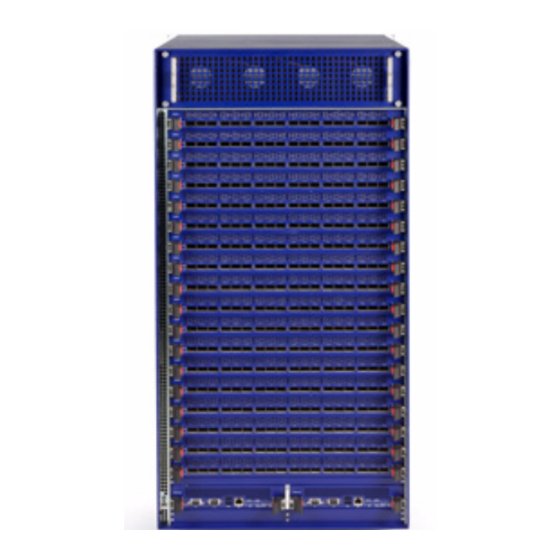
1 Chassis
•
1-18 leafs according to the amount ordered
•
18 - X leaf blanks X = the amount ordered
•
1 leaf fan module
•
1 spine fan module
•
9 spines
•
1- 2 management modules according to the amount ordered. If only 1 management module is ordered
then one MM blank will be in the package.
•
6-8 power cables depending upon your specific order
•
6-8 PSUs depending upon your specific order
•
(8 - X) PSU blanks X = the amount ordered
•
RJ45 to DB9 cable
•
1 Installation kit
•
CD
•
Installation guide
Before you install your new MTS3610 Chassis, unpack the system and check to make sure that all the parts
have been sent, check this against the parts list. Check the parts for visible damages that may have occurred
during shipping.
Note: If anything is damaged or missing, contact your customer representative immediately.
Physical Installation
Note: You will need a mechanical lift, to move and insert the chassis into the rack.
This chassis can be installed in 19" racks with a maximum depth of 81cm.
The switch platform uses 20U of rack space in a standard 19" rack. The switch ships from the factory with
mounting racks on the front side. There are four threaded connectors on the top of the chassis for connecting
eye bolts. The four eye bolts are included in the installation kit. The chassis can be lifted using these four eye
bolts and a mechanical lift. The switch is supported from underneath the unit by a shelf.
Choose a rack which is able to support the mechanical and environmental characteristics of a fully populated
switch chassis as listed in the user manual.
Mellanox Technologies Inc.
350 Oakmead Parkway, Sunnyvale, CA 94085
Document Number
3082
MTS3610 Installation Guide
Warning: This equipment is very heavy. Safety is the first concern. The fully
loaded chassis weighs ~350 lbs (155 kg). Make sure that proper manpower and
equipment are used for transporting and moving the chassis.
Tel: 408-970-3400
Fax: 408-970-3403
www.mellanox.com
Rev 1.2.2
Advertisement
Table of Contents

Subscribe to Our Youtube Channel
Related Manuals for Mellanox Technologies MTS3610


Summary of Contents for Mellanox Technologies MTS3610
- Page 1 Installation guide Before you install your new MTS3610 Chassis, unpack the system and check to make sure that all the parts have been sent, check this against the parts list. Check the parts for visible damages that may have occurred during shipping.
-
Page 2: Esd Connection
Step 2. Plug the other end of the wrist strap to the MTS3610 chassis ESD connector on the front of the switch system or connect it to a valid ground. Make sure that this is a tight fit. - Page 3 MTS3610 Installation Guide Figure 2: Installation Kit Parts Lock down bar Rail slide Eye bolts Caged nuts and bolts Right and Left Cable holders Before starting the procedure, put the ESD strap on and connect it to a valid ground.
- Page 4 MTS3610 Installation Guide Figure 3: Vertical Rails to Cabinet Measurement Note: The side of the chassis with the power supply units will sit flush with the vertical supports of the rack. The side of the chassis with the QSFP connectors will sit at the edge of the shelf closer to the center of the rack.
- Page 5 MTS3610 Installation Guide Figure 6: Shelf Installation Step 8. Tighten all eight bolts into the caged nuts. Inserting the Chassis Step 1. Screw the four Eye bolts to the four corners of the top of the chassis. Step 2. Connect the eye bolts to a Mechanical lifting device.
- Page 6 MTS3610 Installation Guide Figure 8: Face Plate Mounting Bolt Locations Holes in the faceplate for mounting on the rack. Step 8. Slide the chassis onto the shelf until the face plate of the chassis touches the vertical rack support. Step 9.
-
Page 7: Ground Connections
MTS3610 Installation Guide Ground Connections Make sure to connect the ground post to a valid electrical ground. Use a grounding lug and a ground wire of sufficient capacity to safely convey a potential discharge. The chassis is concurrently grounded through each of the PSUs. -
Page 8: Powering Up The Switch Platform
Repeat steps 1 to 3 for each of the remaining power supply units. Note: A fully loaded MTS3610 switch system can draw 5.2 kW of power. Make sure that the outlets and circuits will not be overloaded. Spread out the load over at least two or three circuits. -
Page 9: Configuring The Switch For The First Time
Configuring the Switch for the First Time Step 1. Connect the host PC to the RS-232 port of the MTS3610 switch using the supplied cable. RS-232 port Rev 1.2.2 Mellanox Technologies... - Page 10 MTS3610 Installation Guide Make sure to connect to the RS-232 RJ-45 port of the switch and not to the ETH port. Note: No remote IP connection is available at this stage. Step 2. Configure a serial terminal program (for example, HyperTerminal, minicom, or Tera Term) on your host PC with the settings described in Table 1.
- Page 11 MTS3610 Installation Guide Table 2 - Configuration Wizard Session (Sheet 2 of 2) Wizard Session Display (Example) Comments The wizard displays a summary of your You have entered the following information: choices and then asks you to confirm the 1. Hostname: <hostname>...
-
Page 12: Starting An Ssh Connection To The Switch
MTS3610 Installation Guide TX collisions: switch-1 Starting an SSH Connection to the Switch Step 1. Set up an Ethernet connection between the switch and a local network machine (“the remote machine” henceforth) using a standard RJ-45 connector. Step 2. Connect to the remote machine.
Need help?
Do you have a question about the MTS3610 and is the answer not in the manual?
Questions and answers