
Related Manuals for Mellanox Technologies MTS3600Q-1BNC


Summary of Contents for Mellanox Technologies MTS3600Q-1BNC
- Page 1 InfiniScale® IV 36-Port QSFP 40 Gb/s InfiniBand Switch User Manual P/N: MTS3600Q-1BNC, MTS3600Q-2BNC, MTS3600Q-1UNC, MTS3600Q-2UNC, MTS3600R-1BNC, MTS3600R-2BNC, MTS3600R-1UNC, MTS3600R-2UNC Rev 2.7 www.mellanox.com...
- Page 2 THIS HARDWARE, SOFTWARE OR TEST SUITE PRODUCT (“PRODUCT(S)”) AND ITS RELATED DOCUMENTATION ARE PROVIDED BY MELLANOX TECHNOLOGIES “AS-IS” WITH ALL FAULTS OF ANY KIND AND SOLELY FOR THE PURPOSE OF AIDING THE CUSTOMER IN TESTING APPLICATIONS THAT USE THE PRODUCTS IN DESIGNATED SOLUTIONS. THE CUSTOMER'S MANUFACTURING TEST ENVIRONMENT HAS NOT MET THE STANDARDS SET BY MELLANOX TECHNOLOGIES TO FULLY QUALIFY THE PRODUCTO(S) AND/OR THE SYSTEM USING IT.
-
Page 3: Table Of Contents
4.3 Unmanaged (Externally Managed) Switch 4.3.1 I2C Connector 4.3.2 Updating Firmware 4.3.3 How to Get Mellanox Firmware Tools (MFT) 4.3.4 Open SM Chapter 5 Switch Management Tools 5.1 Chassis Management Chapter 6 FabricIT Management 6.1 Downloading FabricIT Software and Documents Mellanox Technologies... - Page 4 Appendix D Replacement Parts Ordering Numbers Appendix E Avertissements de sécurité d’installation (French) Appendix F Installation - Sicherheitshinweise (German) Appendix G Advertencias de seguridad para la instalación (Spanish) Appendix H Special Regulations Regarding Finland, Sweden, Denmark, and Norway Mellanox Technologies...
-
Page 5: List Of Figures
Figure 16: Two Power Inlets - Electric Caution Notifications Figure 17: Power Supply Unit Extraction Figure 18: Top and Bottom Ports Figure 19: Cable connections to the Switch Figure 20: Host Connection Figure 21: License Key Entitlement Number Figure 22: License Key Generation Form Mellanox Technologies... -
Page 6: List Of Tables
Table 6: PSU Status LED Configurations Table 7: Fan Status LED Configurations Table 8: MTS3600Q Specification Data Table 9: MTS3600R Specification Data Table 10: Switch Certification Status Table 11: InfiniBand QSFP Connector Pinout Table 12: Replacement Parts Ordering Numbers Mellanox Technologies... -
Page 7: Revision History
September 2008 Rev 1.2 Added Reprogramming the MT3600 Through The I2C Port section. Added power cord OPNs to table 11 in Appendix D. September 2008 Rev 1.1 Fixed link to Software package page. September 2008 Rev 1.0 Initial release Mellanox Technologies... -
Page 8: About This Manual
The manual supplied with this package provides an overview of the firm- User’s Manual ware its installation and replacement. The MFT can be downloaded with its Document # 2329 documentation at: http://www.mellanox.com > Support > Download Firmware Tools Mellanox Technologies... -
Page 9: Conventions
QSFP 40Gb/s InfiniBand Switch and the 36-port QSFP 20Gb/s InfiniBand Switch, unless explicitly indicated otherwise. Mellanox Part Numbering Legend Table 3 - Part Numbering Legend Place Field Decoder Mellanox Technologies System Type S = Switch Model 36 = InfiniScale IV Form factor 00 = Rack mounted switch, 10 = Chassis InfiniBand Port Config. -
Page 10: Chapter 1 Overview
The serial number and product version information are found on the label seen in the figure below. Figure 1: Generic Product label Also on this label is the GUID identifier for the switch. There is also a label with the MAC for the management module. Mellanox Technologies... -
Page 11: Figure 2: Management Module Label
QDR InfiniBand Switch Platform User Manual Rev 2.7 Figure 2: Management Module Label Mellanox Technologies... -
Page 12: Chapter 2 Internally Managed Vs. Unmanaged (Externally Managed)
Chassis Management is included with purchase, and an additional fab- ric management option, FabricIT-EFM, can be used with purchase of an additional license. Should your unmanaged switch have CONSOLE, Ethernet, and USB connectors, they will not work. Only the I2C connector will work on unmanaged switches. Mellanox Technologies... -
Page 13: Chapter 3 Basic Operation And Installation
Hot-Swap ability and it is connected to a power source. If two PSUs are installed and only one PSU is connected to a power supply the second PSU LED will be red. If only one PSU is installed in the switch, the second PSU LED will be off. Mellanox Technologies... - Page 14 For more information See “Troubleshooting” on page 43. If the PSU LEDs are not green, this indicates a problem with the power supplies. Only run the switch if at least one of the PSU LEDs is green. Mellanox Technologies...
-
Page 15: Figure 4: Power, Fan, And System Leds
3.1.1.2 Power Supply Status Indicators The MTS3600 36 Port Switch is available with one or two factory installed Power Supply Units. For switches with only one unit installed, a second Power Supply Unit can be added to increase Mellanox Technologies... -
Page 16: Figure 5: Mts3600 Qsfp Power Side Panel
PSU Status LED colors. page 15 3.1.1.3 Fan Status Indicators The indicator labeled “Fans” is located just to the left of the primary power supply unit, next to PSU 1. The following fan status conditions are possible: Mellanox Technologies... -
Page 17: Qsfp Cable Power Budget Classification
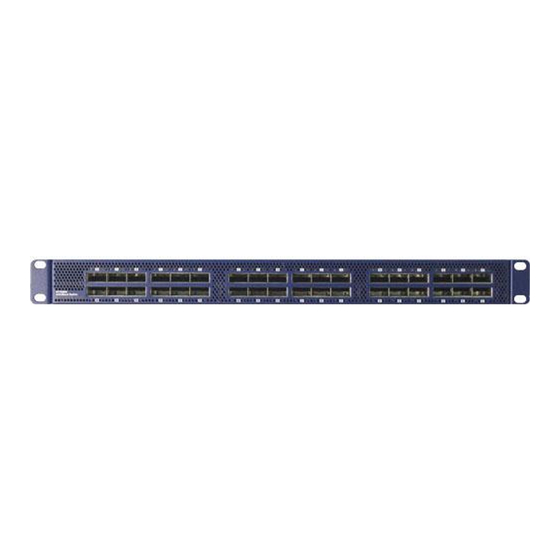
The Connector side of the switch has 36 QSFP ports. These are placed in two rows, 18 ports to a row. The ports are labelled as shown in Figure 7. The bottom row ports are flipped from the top row. See Figure 8 for bottom row - top row port orientation. Mellanox Technologies... -
Page 18: Management And Fw Updating Interfaces
. These connectors do not work in unmanaged switches. • 1 serial CONSOLE port. Use this to connect to a local host PC. This connector does not work in unmanaged switches. Figure 9: Management Interfaces System Fans CONSOLE PSU 1 PSU 2 Mellanox Technologies... -
Page 19: Package Contents
Before you install your new MTS3600 switch, unpack the system and check to make sure that all the parts have been sent, check this against the parts list. Check the parts for visible damage that may have occurred during shipping. Mellanox Technologies... -
Page 20: Switch Platform Installation And Operation
Spanish see Section G,“Advertencias de seguridad para la instalación (Spanish),” on page For special regulations regarding Finland, Sweden, Denmark, and Norway see Section H,“Special Regulations Regarding Finland, Sweden, Denmark, and Norway,” on page 62. 1. Installation Instructions Read all installation instructions before connecting the equipment to the power source. Mellanox Technologies... - Page 21 In general you should fill the rack with equipment starting from the bottom to the top. 8. Equipment Installation This equipment should be installed, replaced, or serviced only by trained and qualified personnel. Mellanox Technologies...
-
Page 22: Mechanical Installation
• grounding wire sufficient to reach a valid ground. • ESD mat Parts included in the installation kit: • 2 rails • 8 recessed flat head screws • 2 rail slides • 4 caged nuts • 8 pan head screws M6 • 2 metal washers Mellanox Technologies... -
Page 23: Figure 10: Rack Installation Kit Parts
IB connectors can be even with the vertical rack support. The other side of the switch will be further inside of the rack. Things to consider before choosing where to mount the rails and rail slides. Mellanox Technologies... -
Page 24: Figure 11: Which Side Of The Rack Do You Want The Connectors
Tighten the screws to 3Nm or 26.5 pound inches. Figure 12: Screwing the Rail Slide onto the switch This side of the switch will be next to the vertical rack support. Mellanox Technologies... -
Page 25: Figure 13: Caged Nut Spacing
Check the Status LEDs and confirm that all of the LEDs show status lights consistent with normal operation. 12. You can start connecting all of the cables to the switch. Make sure that the Rail kit is compatible with your rack. Mellanox Technologies... -
Page 26: Figure 15: Which Side Of The Rack Do You Want The Connectors
… … … … Warning: Any yellow status LEDs is cause for concern and must be dealt with immediately. It can take up to 3 minutes to boot up, during which time the status LED may indicate red. Mellanox Technologies... -
Page 27: Grounding The Switch
Caution: When turning off the switch, make sure ALL LEDS are off to ensure a powered down status. Mellanox Technologies... -
Page 28: Extracting And Inserting The Power Supply Unit
With both power supplies installed in the redundant configuration, either PSU may be extracted without bringing down the system. Make sure that the PSU that you are NOT replacing is showing all green, for both the PSU and status indicators. Mellanox Technologies... -
Page 29: Figure 17: Power Supply Unit Extraction
Insert the other end of the power cord into an outlet of the correct voltage. The green PSU indicator should light and the yellow indicator should remain off. If not, repeat the whole procedure to extract the PSU and re-insert it. Mellanox Technologies... -
Page 30: Infiniband Cable Installation
Care should be taken not to impede the air exhaust flow through the ventilation holes next to the InfiniBand ports. Cable lengths should be used which allow for routing horizontally around to the side of the chassis before bending upward or downward in the rack. Mellanox Technologies... -
Page 31: Extracting And Inserting The Fan Unit
Make sure the mating connector of the new unit is free of any dirt and/or obstacles. Insert the fan unit by sliding it into the opening until slight resistance is felt. Continue press- ing the fan unit until it seats completely. Mellanox Technologies... -
Page 32: Disassembly Of The Switch From The Rack
According to the WEEE Directive 2002/96/EC, all waste electrical and electronic equipment (EEE) should be collected separately and not dis- posed of with regular household waste. Dispose of this product and all of its parts in a responsible and environ- mentally friendly way. Mellanox Technologies... -
Page 33: Chapter 4 Management And Tools Overview
• SNMP agent, 3rd party tool integration • GUI • subnet manager • performance/provisioning manager • congestion and notification manager • QoS manager • adaptive routing manager • cluster diagnostics manager The Subnet management features include: • upgrading drivers Mellanox Technologies... -
Page 34: Configuring The Switch For The First Time
Hook up the supplied harness cable (HAR00040) from the connector labelled CONSOLE to the DB9 connector of the local host PC. Figure 20: Host Connection Connect the host PC to here System Fans CONSOLE PSU 1 PSU 2 Mellanox Technologies... -
Page 35: Starting A Remote Connection To The Switch
=> Downloads => Firmware. For instructions on downloading FW see http://www.mellanox.com => Downloads => Firmware Tools. Be sure to download the user man- ual appropriate to your OS. Read the instructions in the User manual for the FW update procedure. Mellanox Technologies... -
Page 36: Updating Firmware
-W- Topology file is not specified. Reports regarding cluster links will use direct routes. Loading IBDM from: /usr/local/lib/ibdm1.2 -I- Using port 1 as the local port. -I- Discovering ... 3 nodes (2 Switches & 1 CA-s) discovered. -I--------------------------------------------------- -I- Bad Guids/LIDs Info -I--------------------------------------------------- Mellanox Technologies... - Page 37 -I- skip option set. no report will be issued -I--------------------------------------------------- -I- Bad Links Info -I--------------------------------------------------- -I- No bad link were found ---------------------------------------------------------------- -I- Stages Status Report: STAGE Errors Warnings Bad GUIDs/LIDs Check Link State Active Check Performance Counters Report Mellanox Technologies...
- Page 38 MST PCI configuration module loaded Inband devices: ------------------- /dev/mst/CA_MT25418_sw005_HCA-1_lid-0x0001 /dev/mst/SW_MT47396_lid-0x0011 /dev/mst/SW_MT48438_lid-0x0003 [root@mymach]> II. Using the ibnetdiscover tool: Run: [root@mymach]# ibnetdiscover | grep 00000006660abcd0 | grep -w Switch Switch 24 "S-00000006660abcd0" "MT47396 Infiniscale-III Mellanox Technologies" base port 0 lid 17 lmc 0 Mellanox Technologies...
-
Page 39: How To Get Mellanox Firmware Tools (Mft)
4.3.4 Open SM To manage the Mellanox switch system using OFED, download Mellanox Open Fabrics from http://www.mellanox.com > Downloads > InfiniBandSW/Drivers. Be sure to read and follow all of the instructions regarding the installation and use of these tools. Mellanox Technologies... -
Page 40: Chapter 5 Switch Management Tools
The chassis manager will give the user access to: • switch temperatures • power supply voltages • fan unit information • power unit information • Flash memory The manager also has the ability to burn new FW on the switch. Mellanox Technologies... -
Page 41: Chapter 6 Fabricit Management
Mellanox online license tool at http://license.mellanox.com. The Switch Serial Number can be found on the pull-out tab or the box labeling. For the serial number location on the chassis see Section 1.1, “Serial Number and Product Version Information,” on page 10. Mellanox Technologies... -
Page 42: Fabricit Management And Inspection License
Without the license, you will not be able to run a Subnet Manager on the switch nor run advanced fabric diagnostics. For information on installation, please refer to the FabricIT Enterprise Fabric Management Soft- ware CLI User’s Manual. Mellanox Technologies... -
Page 43: Chapter 7 Troubleshooting
If you find dust blocking the holes it is recommended to clean the fan unit and remove the dust from the front and rear panels of the switch using a vacuum cleaner. The green power LED for the fans does not come on: Check that the Power LEDs are on. Mellanox Technologies... - Page 44 The last software update did not succeed: Connect the RS232 connector (CONSOLE) to a laptop. Push the reset button on the switch or management module. You will have ~ 5 seconds to stop the U-Boot by pressing Control-B. Mellanox Technologies...
- Page 45 01 00 15b3 bd34 0c06 00 Net: ppc_4xx_eth0, ppc_4xx_eth1 Hit Ctrl+B to stop autoboot: 0 Mellanox FabricIT Boot Menu: 1. EFM_PPC_M460EX EFM_1.1.1000 2010-06-24 16:32:03 ppc 2. EFM_PPC_M460EX EFM_1.1.1200 2010-06-25 18 :00:03 ppc 3. U-Boot prompt Choice: Select the image to boot. Mellanox Technologies...
-
Page 46: Appendix A Specification
Japan: VCCI, Class A Environmental: EU: IEC 60068-2-64: Ran- dom Vibration EU: IEC 60068-2-29: Shocks, Type I / II EU: IEC 60068-2-32: Fall Test Acoustic: ISO 7779 ETS 300 753 Sound power level: 70.5 dB(A) or 7.1 Bel Mellanox Technologies... -
Page 47: Table 9: Mts3600R Specification Data
Active cables: TBD / TBD TBD / TBD QSFP Max Power per port for active cables: 3.5W Temperature: 10° to 45° Celsius Humidity: 10% - 90% non-condensing Shock and Vibration: ETSI EN 300 019-2-2: 1999-09 Protocol Support Regulatory Compliance Mellanox Technologies... -
Page 48: Table 10: Switch Certification Status
EMC Certification Statements Table 10 lists the approved certification status per switch in different regions of the world. Table 10 - Switch Certification Status ICES VCCI Switch P/N Class Class Class cTUVus (Japan) (USA) (Europe) (Canada) MTS3600Q-1UNC MTS3600R-1BNC MTS3600Q-1BNC Mellanox Technologies... - Page 49 § 15.21 Statement Warning! Changes or modifications to this equipment not expressly approved by the party responsible for compliance (Mellanox Technologies) could void the user's authority to operate the equipment. §15.105(a) Statement NOTE: This equipment has been tested and found to comply with the limits for a Class A digital device, pursuant to Part 15 of the FCC Rules.
- Page 50 Class A Device This device is registered for EMC requirements for industrial use. The seller or buyer should be aware of this. If this type was sold or purchased by mistake, it should be replaced with a residential-use type. Mellanox Technologies...
-
Page 51: Appendix B Switch Hardware Components
QDR InfiniBand Switch Platform User Manual Rev 2.7 Appendix B: Switch Hardware Components Place for Optional Secondary Power Primary Power Supply Unit Fan Unit Supply Unit Mellanox Technologies... -
Page 52: Appendix C Qsfp Interface
+3.3 V Power supply transmitter Vcc 1 +3.3 V Power Supply LPMode Low Power Mode Ground Tx3p Transmitter Non-Inverted Data Input Tx3n Transmitter Inverted Data Input Ground Tx1p Transmitter Non-Inverted Data Input Tx1n Transmitter Inverted Data Input Ground Mellanox Technologies... - Page 53 QDR InfiniBand Switch Platform User Manual Rev 2.7 18.35 View into Rear of Connector 8.50 18.35 View into Front of Cage 8.50 Mellanox Technologies...
-
Page 54: Appendix D Replacement Parts Ordering Numbers
Power cord Type G for UK ACC000208 Power cord Type D for India ACC000209 Power cord Type I for China ACC000210 Power cord Type J for Switzerland ACC000211 Power cord Type B for Japan, ACC000212 Power cord Type I for Australia ACC000213 Mellanox Technologies... -
Page 55: Appendix E Avertissements De Sécurité D'installation (French)
7. Montage et entretien sur baie Lorsque ce produit est monté ou entretenu sur baie, il faut prendre des précaut- ions spéciales pour s’assurer que le système reste stable. En général, il faut remplir la baie avec du matériel de bas en haut. Mellanox Technologies... - Page 56 L’élimination de ce matériel doit s’effectuer dans le respect de toutes les législ- ations et réglementations nationales en vigueur. 10. Codes électriques locaux et nationaux Ce matériel doit être installé dans le respect des codes électriques locaux et nationaux. Mellanox Technologies...
-
Page 57: Appendix F Installation - Sicherheitshinweise (German)
Vorsichtsmaßnahmen zu ergreifen, um die Stabilität des Systems zu gewährleisten. Im Allgemeinen sollten Sie das Gestell von unten nach oben mit Geräten füllen. 8. Geräteinstallation Diese Gerät sollte nur von geschultem und qualifiziertem Personal installiert, ausgetauscht oder gewartet werden. Mellanox Technologies... - Page 58 Rev 2.7 9. Geräteentsorgung Die Entsorgung dieses Geräts sollte unter Beachtung aller nationalen Gesetze Bestimmungen erfolgen. 10. Regionale und nationale elektrische Bestimmungen Dieses Gerät sollte unter Beachtung der regionalen und nationalen elektrischen Bestimmungen installiert werden. Mellanox Technologies...
-
Page 59: Appendix G Advertencias De Seguridad Para La Instalación (Spanish)
Al instalar o realizar el mantenimiento de este aparato en un bastidor, es preciso adoptar precauciones especiales para garantizar que el sistema se mantenga estable. En general, en un bastidor, los equipos se deben insta- lar comenzando desde abajo hacia arriba. Mellanox Technologies... - Page 60 300 voltios nominal, con cobertura protectora aislante de PVC. El cable debe tener un enchufe moldeado con capuchón de 250 voltios nomi- nal, 10 A. ADVERTENCIA: Alta corriente de fuga. Es esencial efectuar la conexión a tierra antes de conectar la alimentación. Mellanox Technologies...
- Page 61 (EEE) se deben recolectar por separado y no se deben eliminar junto con residuos domésticos. Al deshacerse de este producto y de todas sus partes, hágalo de una manera res- ponsable y respetuosa con el medio ambiente. Mellanox Technologies...
-
Page 62: Appendix H Special Regulations Regarding Finland, Sweden, Denmark, And Norway
Do not connect this unit to any outlet that is not fully grounded! • Finland “Laite on liitettävä suojamaadoituskoskettimilla varust- ettuun pistorasiaan” • Norway “Apparatet må tilkoples jordet stikkontakt” Unit is intended for connection to IT power systems for Norway only. • Sweden “Apparaten skall anslutas till jordat uttag.” Mellanox Technologies...
Need help?
Do you have a question about the MTS3600Q-1BNC and is the answer not in the manual?
Questions and answers