
Related Manuals for Mellanox Technologies MIS5600Q-10DNC


Summary of Contents for Mellanox Technologies MIS5600Q-10DNC
- Page 1 Dismantling Guide OPNs: MIS5600Q-10DNC, MIS5300Q-6DNC, MIS5200Q-4DNC, MIS5100Q-3DNC, MSX6536-10R, MSX6536-NR, MSX 6518-NR, MSX 6512-NR Rev 1.1 www.mellanox.com Mellanox Technologies Confidential...
- Page 2 THIS HARDWARE, SOFTWARE OR TEST SUITE PRODUCT (“PRODUCT(S)”) AND ITS RELATED DOCUMENTATION ARE PROVIDED BY MELLANOX TECHNOLOGIES “AS-IS” WITH ALL FAULTS OF ANY KIND AND SOLELY FOR THE PURPOSE OF AIDING THE CUSTOMER IN TESTING APPLICATIONS THAT USE THE PRODUCTS IN DESIGNATED SOLUTIONS. THE CUSTOMER'S MANUFACTURING TEST ENVIRONMENT HAS NOT MET THE STANDARDS SET BY MELLANOX TECHNOLOGIES TO FULLY QUALIFY THE PRODUCTO(S) AND/OR THE SYSTEM USING IT.
-
Page 3: Table Of Contents
Contents Rev 1.1 Contents Revision History ............................ 4 Preface ..............................4 Switch OPNs ............................4 Policy Statement ............................ 5 Chassis Switch Systems - RoHS ......................5 Dismantling Instructions ........................ 6 General Information ........................ 6 Leaf ............................6 Extraction of the Modules ......................7 Extracting the Power Supply Units (PSU) ................ -
Page 4: Revision History
Intended Audience This manual is intended for technicians who dismantle the switch systems as a reference for WEEE recyclers. Mellanox Technologies emphasizes the importance of carefully following all procedures described in this guide to prevent personal injury. Switch OPNs This document is valid for all switch OPNs listed in Table 2. -
Page 5: Policy Statement
Mellanox Technologies recognizes the importance of developing connectivity solutions that not only enable our customers to optimize their data centers performance, but also protect the environment and ensure that future generations enjoy its bounties. Mellanox Technologies is committed, therefore, to meeting the requirements of the European Union’s WEEE (waste electrical and electronic equipment) directive. -
Page 6: Dismantling Instructions
Rev 1.1 Dismantling Instructions Dismantling Instructions This document provides detailed instructions for dismantling the InfiniBand chassis switch systems. Follow the instructions in the order they are presented. General Information The switch system is assembled using screws, and modules with handles, snaps and latches. To disassemble the switch system parts you will need a small Philips screwdriver and a medium slotted screwdriver. -
Page 7: Extraction Of The Modules
Dismantling Document Rev 1.1 Figure 1: Front and Rear View of the MIS5600 Fans Cover to PSUs Management Modules IS5600 Power modules S.Fans L.Fans Master CONSOLE S.Fans L.Fans Master CONSOLE are behind the Mellanox Leafs IS5600 IS5600 IS5600 covers. Mellanox Mellanox Spines 1285mm... -
Page 8: Extracting The Fan Units
Rev 1.1 Extraction of the Modules Figure 3: Power Supply Covers IS5600 Mellanox IS5600 IS5600 IS5600 Mellanox Mellanox 1285mm Figure 4: Power Supply Unit Latch Handle FAIL 3. Grasping the handle with one hand, push the black latch release while pulling the handle outward. -
Page 9: Extracting All Leaf Boards
Dismantling Document Rev 1.1 Figure 5: Fan Module Extracting all Leaf Boards Each leaf board has an ejector that locks the board in place and serves as a lever for seating or extracting. 1. Disconnect all cables connected to the leaf. Figure 6: Leaf Latch Leaf Leaf... -
Page 10: Extracting A Spine Board
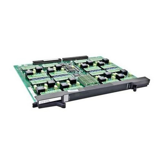
Rev 1.1 Extraction of the Modules Figure 7: Chassis Leaf Heat sink screws Leaf board screw locations 6. After the cover is removed unscrew the 5 Philips screws and remove the board from the casing. 7. Turn the board over and remove the heat sink from the board by unscrewing the 4 slotted screws and remove the heat sink from the board. -
Page 11: Extracting The Management Modules
Dismantling Document Rev 1.1 Figure 8: Ejector Latch Management Module /Spine Management Module /Spine Figure 9: Spine Board Spine Fans 4. Remove the bottom cover. 5. After the spine board is removed unscrew the 4 Philips screws and remove the board from the casing. -
Page 12: Battery Extraction
Rev 1.1 Extraction of the Modules Figure 10: Ejector Latch Management Module /Spine Management Module /Spine 4. Remove the bottom cover. 5. After the cover is removed unscrew the 4 Philips screws and remove the board from the casing. 6. Remove the heat sink from the board by unscrewing the 4 slotted screws and remove the heat sink from the board. -
Page 13: Board Extraction From The Chassis Body
Dismantling Document Rev 1.1 Board Extraction from the Chassis Body The chassis body contains the following PC boards: midplane power backplanes; the 648 port has 4, other chassis have less power backplanes fan boards; the 648 port has 2, other chassis 1 fan board 1. - Page 14 Rev 1.1 Board Extraction from the Chassis Body 13. Once the spine framework is removed, unscrew the 4 power backplanes. 14. Unscrew the Midplane. 15. For the 648 port only unscrew and remove the lower fan board.
Need help?
Do you have a question about the MIS5600Q-10DNC and is the answer not in the manual?
Questions and answers