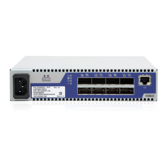
Mellanox Technologies InfiniScale MIS5022Q-1BRR User Manual
Iv 8-port qsfp 40 gb/s infiniband switch
Hide thumbs
Also See for InfiniScale MIS5022Q-1BRR:
- User manual (51 pages) ,
- Dismantling manual (13 pages)

Related Manuals for Mellanox Technologies InfiniScale MIS5022Q-1BRR


Summary of Contents for Mellanox Technologies InfiniScale MIS5022Q-1BRR
- Page 1 InfiniScale® IV 8-Port QSFP 40 Gb/s InfiniBand Switch User Manual P/N:MIS5022Q-1BRR, MIS5022Q-1BFR, MIS5022Q-1BFR, MIS5022Q-1BRR, MIS5022Q-1BFC, MIS5022Q-1BRC Rev 1.4 www.mellanox.com...
- Page 2 THIS HARDWARE, SOFTWARE OR TEST SUITE PRODUCT (“PRODUCT(S)”) AND ITS RELATED DOCUMENTATION ARE PROVIDED BY MELLANOX TECHNOLOGIES “AS-IS” WITH ALL FAULTS OF ANY KIND AND SOLELY FOR THE PURPOSE OF AIDING THE CUSTOMER IN TESTING APPLICATIONS THAT USE THE PRODUCTS IN DESIGNATED SOLUTIONS. THE CUSTOMER'S MANUFACTURING TEST ENVIRONMENT HAS NOT MET THE STANDARDS SET BY MELLANOX TECHNOLOGIES TO FULLY QUALIFY THE PRODUCT(S) AND/OR THE SYSTEM USING IT.
-
Page 3: Table Of Contents
5.3.2 Disassembly Procedure — Side by Side Installation 5.4 Disposal 5.5 Updating Firmware 5.5.1 Current Firmware Revision 5.5.2 Open SM Chapter 6 Troubleshooting Appendix A Specification Approved Cables EMC Certifications Appendix B SFP+ Interface Appendix C QSFP Interface Mellanox Technologies... - Page 4 Appendix D Replacement Parts Ordering Numbers Appendix E Avertissements de sécurité d’installation (French) Appendix F Installation - Sicherheitshinweise (German) Appendix G Advertencias de seguridad para la instalación (Spanish) Appendix H Special Regulations Regarding Finland, Sweden, Denmark, and Norway Mellanox Technologies...
-
Page 5: List Of Figures
Figure 11: Screw on the Switch Mounted Rails Figure 12: Caged Nut Placement Figure 13: Front Panel Orientation Figure 14: Top and Bottom Ports Figure 15: MTUSB-1 with Cables Figure 16: I2C Cable Connected to IS5022 Figure 17: QSFP Male and Female Connections Mellanox Technologies... -
Page 6: List Of Tables
Port Connector Physical and Logical Link Indications Table 7: Installation Kit Options Table 8: Installation Kit According to Rack Size Table 9: IS5022 Specification Data Table 10: SFP+ Pinout Table 11: InfiniBand QSFP Connector Pinout Table 12: Replacement Parts Ordering Numbers Mellanox Technologies... -
Page 7: Revision History
Added note and figure to blank panel installtion step. Made changes to the installation process for the two switch frame. Made changes to FW burning sections. Feb. 2011 Rev 1.1 Removed UID LED support Jan. 2011 Rev 1.0 Initial Release Mellanox Technologies... -
Page 8: About This Manual
The following icons are used throughout this document to indicate information that is important to the user. This symbol signals recommendations to the user. This symbol indicates information that is helpful to the user. This symbol indicates a situation that can potentially cause damage to hardware or software. Mellanox Technologies... -
Page 9: Mellanox Part Numbering Legend
Rev 1.4 BEWARE! This symbol indicates a situation that can potentially cause personal injury or damage to hardware or software. Mellanox Part Numbering Legend Place Field Decoder Mellanox Technologies System Type InfiniScale Switch Model Family Form factor 22 = 8 Ports... -
Page 10: Chapter 1 Overview
Serial Number and Product Version Information The serial number and GUID for the switch are found on the Mellanox logo. The serial number and product version information are found on the label seen in the figure below. Mellanox Technologies... - Page 11 InfiniScale® IV 8-Port QSFP 40 Gb/s InfiniBand Switch User Manual Rev 1.4 Also on this label is the GUID identifier for the switch. Generic Product label Figure 1: Management MAC Label Management MAC: 0002C902004C Mellanox Technologies...
-
Page 12: Chapter 2 Installation Safety Warnings
During periods of lightning activity, do not work on the equipment or connect or dis- connect cables. 6. Copper Cable Connecting/Disconnecting Copper cables are heavy and not flexible, as such they should be carefully attached to or detached from the connectors. Refer to the cable manufacturer for special warnings/ instructions. Mellanox Technologies... - Page 13 This device must be installed according to the latest version of the country national electrical codes. For North America, equipment must be installed in accordance to the applicable requirements in the US National Electrical Code and the Canadian Electrical Code. Mellanox Technologies...
- Page 14 According to the WEEE Directive 2002/96/EC, all waste electrical and electronic equipment (EEE) should be collected separately and not disposed of with regular household waste. Dispose of this product and all of its parts in a responsible and environmentally friendly way. Mellanox Technologies...
-
Page 15: Chapter 3 Externally Managed Switches
Externally managed switches must be managed by management software installed on a node or on another managed switch that can be anywhere in the fabric. This can be OpenSM, MLNX-OS, Mellanox FabricIT™ EFM, Mellanox UFM™, or a third party Subnet Manager. Mellanox Technologies... -
Page 16: Chapter 4 Hardware Basic Operation And Installation
When the switch is plugged in, within three seconds • The Status LED should light up green. • The Fan LED should light up green. • The Bad Port LED should be off. • The Unit ID LED should be off. Mellanox Technologies... -
Page 17: Table 3: Switch Status Led Configurations
The status indicator is located on the left side of the front panel (connector side) of the unit. The following status conditions are possible: Table 3 - Switch Status LED Configurations LED Configuration LED Description No power to the switch. Solid Green OK – the switch is running. All OK. Blinking Green Switch is booting up. Mellanox Technologies... -
Page 18: Table 4: Fan Led Configurations
OK – all ports are up and running. Flashing Orange Error – one or possibly more ports has just received a symbol error. This LED shows symbol errors. Possible causes for this are: • bad cable • bad connection • bad connector Mellanox Technologies... -
Page 19: Port Connector Led Assignment
4.1.1.5 UID LED Switch Identifier The UID LED is a debug feature that will become available to customers in the near future. For details please contact Mellanox Technologies support. 4.1.1.6 Port Connector LED The port LEDs are assigned to the ports as in figure: 4.1.2 Port Connector LED Assignment... -
Page 20: Qsfp Cable Power Budget Classification
There is one interface to connect to the switch. It is an I2C RJ45 interface labelled “I2C”. Use this connector to update firmware (as a last resort) and for advanced debug. Update firmware inband only. 4.5.1 RJ-45 Connector (I2C) There is an “I2C” interface on the front panel. Mellanox Technologies... - Page 21 Warning: Any red status LED is cause for concern and must be dealt with immediately. It can take up to 30 seconds to boot up, during which time the status LED may indicate red. Mellanox Technologies...
-
Page 22: Chapter 5 Installation
8cm (3”) of space to the front and rear of the switch. This will ensure proper airflow through the chassis. This is crucial for maintaining good airflow at ambient temperature. In particular, route cables so that they do not impede the air into or out of the chassis. Mellanox Technologies... -
Page 23: Installing The Switch In The Rack
Peel and stick the four rubber bumpers into the bottom of the switch. Place them in the round circles. Figure 7: Placing the Bumpers Bottom of the switch Place on a flat surface. Make sure the switch sits solid on the surface. Connect the power cord. Mellanox Technologies... -
Page 24: Installation Procedure For A Single Switch Center-Of-Rack Installation
ESD strap is touching your skin and that the other end is connected to a verified ground. Screw the two front brackets to the front side of the switch using 4 flat head screws for each bracket. Figure 8: Installation Kit for a Single Centered Installation Mellanox Technologies... -
Page 25: Installation Procedure For A Side By Side Installation
• 4 switch mounted rails • 8 pairs of caged nuts and bolts • 24 flat head screws • 1 blank cover The installation kits come with enough switch mounted rails and flat head screws to install two switches. Mellanox Technologies... - Page 26 ESD strap is touching your skin and that the other end is connected to a verified ground. Screw the two switch mounted rails to the switch using six flat head screws per rail. Figure 11: Screw on the Switch Mounted Rails Mellanox Technologies...
- Page 27 Install the blank panel into the frame opposite the switch, or install a second switch. The front panel is not symetrical. The large radius always goes ot the center of the frame. Figure 13: Front Panel Orientation Large radius Small radius Small radius Mellanox Technologies...
-
Page 28: Power Connections And Initial Power On
If the fan status indicator is not green then unplug the power connection and check that the fan module is inserted properly and that the mating connector of the fan unit is free of any dirt and/or obstacles. Mellanox Technologies... -
Page 29: Grounding The Switch
Figure 14: Top and Bottom Ports To remove, disengage the locks and slowly pull the connector away from the port receptacle. The LED indicator will turn off when the cable is unseated. Mellanox Technologies... -
Page 30: Supported Approved Cables
Unplug the power cord. Remove the ground wire. Unscrew the 2 center bolts from the connector side of switch. Slide the switch from the rack. Remove the rail slides rails from the rack. Remove the 10 caged nuts. Mellanox Technologies... -
Page 31: Disposal
Make sure all subnet ports are in the active state. One way to check this is to run opensm, the Subnet Manager. [root@mymach]> /etc/init.d/opensmd start opensm start [ OK ] Mellanox Technologies... - Page 32 Query the switch to determine the current firmware version: [root@mymach]> flint -d /dev/mst/SW_MT48438_lid-0x0003 q Image type: FW Version: 7.3.0 Device ID: 48438 Chip Revision: Description: Node Sys image GUIDs: 0002c902004177d8 0002c902004177db Board ID: n/a (MT_0D00110012) Mellanox Technologies...
- Page 33 RJ45 male. Use the cable that matches your switch. The other is a USB cable with one type A host connection to be connected to the server or PC and a type B connection to be connected to the MTUSB adapter. Mellanox Technologies...
-
Page 34: Open Sm
To manage the Mellanox switch system using OFED, download Mellanox OpenFabrics from http://www.mellanox.com > Support > InfiniBand Software and Drivers. Be sure to read and follow all of the instructions regarding the installation and use of these tools. Mellanox Technologies... -
Page 35: Chapter 6 Troubleshooting
Check that the connections are good (no cable weight on the connector, no twists in the cable at the connector, etc.). Check the port connectors at both ends. The switch is off: Unplug the switch. Wait 5 minutes. Plug in the switch. If the switch does not come on, check the power supply. Mellanox Technologies... - Page 36 Wait 5 minutes. Plug in the switch. If the switch does not come on, check the power supplies. If the switch comes on, use the management software to determine the cause of the shut- down. Reset the switch. Mellanox Technologies...
-
Page 37: Appendix A Specification
Max: 8 port QDR Optical Cable Passive Cables Max Length: Active Cables Port Types: QSFP QSFP Max Power per port for active cables: 2.0W Temperature: 0 to 45 Celsius Humidity: 10% - 90% non-condensing Protocol Support Regulatory Compliance Mellanox Technologies... -
Page 38: Approved Cables
For a list of all approved cables see: www.mellanox.com/related-docs/user_manuals/Mellanox_approved_cables.pdf EMC Certifications The list of approved certifications per switch in different regions of the world is located on the Mellanox website at: www.mellanox.com/related-docs/user_manuals/Regulatory_and_Compliance_Guide.pdf EMC statements are also in the Regulatory and Compliance Guide. Mellanox Technologies... -
Page 39: Appendix B Sfp+ Interface
InfiniScale® IV 8-Port QSFP 40 Gb/s InfiniBand Switch User Manual Rev 1.4 Appendix B: SFP+ Interface 13.90 11.85 1.55 0.50 8.50 0.60 2.55 1.80 44.95 56.50 Mellanox Technologies 13.60 14.80 13.70 MTSFPP-SR Module Mellanox Technologies... -
Page 40: Table 10: Sfp+ Pinout
Loss of Signal indication. Logic 0 indicates normal operation. No connection required VeeR Receiver Ground (Common with Transmitter Ground) VeeR Receiver Ground (Common with Transmitter Ground) Receiver Inverted DATA out. AC Coupled Receiver Non-inverted DATA out. AC Coupled Mellanox Technologies... - Page 41 MOD_ABS pulls line low to indicate module is plugged in. e. LOS is open collector output. Should be pulled up with 4.7kΩ – 10kΩ on host board to a voltage between 2.0V and 3.6V. Logic 0 indicates normal operation; logic 1 indicates loss of signal. Mellanox Technologies...
-
Page 42: Appendix C Qsfp Interface
+3.3 V Power supply transmitter Vcc 1 +3.3 V Power Supply LPMode Low Power Mode Ground Tx3p Transmitter Non-Inverted Data Input Tx3n Transmitter Inverted Data Input Ground Tx1p Transmitter Non-Inverted Data Input Tx1n Transmitter Inverted Data Input Ground Mellanox Technologies... - Page 43 InfiniScale® IV 8-Port QSFP 40 Gb/s InfiniBand Switch User Manual Rev 1.4 Figure 17: QSFP Male and Female Connections 18.35 View into Rear of Connector 8.50 18.35 View into Front of Cage 8.50 Mellanox Technologies...
-
Page 44: Table 12: Replacement Parts Ordering Numbers
Power cord Type G for UK ACC000208 Power cord Type D for India ACC000209 Power cord Type I for China ACC000210 Power cord Type J for Switzerland ACC000211 Power cord Type B for Japan, ACC000212 Power cord Type I for Australia ACC000213 Mellanox Technologies... - Page 45 6. Orages – dangers électriques Pendant un orage, il ne faut pas utiliser le matériel et il ne faut pas brancher ou débrancher les câbles. Mellanox Technologies...
- Page 46 L’élimination de ce matériel doit s’effectuer dans le respect de toutes les législations et réglementations nationales en vigueur. 13. Codes électriques locaux et nationaux Ce matériel doit être installé dans le respect des codes électriques locaux et nationaux. Mellanox Technologies...
- Page 47 Conformément à la Directive WEEE 2002/96/EC, les déchets d'équipements élec- triques et électroniques (EEE) doivent être triés et ne peuvent être éliminés avec les déchets ménagers. Veuillez disposer de ce produit et de tous ses composants de manière responsable et respectueuse de l’environnement. Mellanox Technologies...
- Page 48 Anschlüsse angebracht bzw. davon getrennt werden. Lesen Sie die speziellen Warnungen und Anleitungen des Kabelherstellers. 7. Gafahr des elektrischen Schocks. Gafahr des elektrischen Schocks. Entferrnen des Netzsteckers elnes Netzteils spannungs- frei. Um alle Einhieten spannungsfrei zu machen sind die Netzstecker aller Netzteile zu entfernen Mellanox Technologies...
- Page 49 Achtung – Nutzung von Steuerungen oder Einstellungen oder Ausführung von Proze- duren, die hier nicht spezifiziert sind, kann zu gefährlichem Strahlenkontakt führen.. Klasse 1 Laserprodukt und Referenzen zu den aktuellsten Lasterstandards : ICE 60 825-1:1993 + A1:1997 + A2:2001 und EN 60825-1:1994+A1:1996+ A2:2001 Mellanox Technologies...
- Page 50 19. Zweipolige bzw. Neutralleiter-Sicherung im Netzteil Achtung: Zweipolige bzw. Neutralleiter-Sicherung im Netzteil. Netzstecker ziehen, um sicher- zustellen, daß keine Spannung am Gerät anliegt. Entfernen Sie alle Netzkabel vor dem Öffnen der Abdeckung dieses Produkts oder dem Berühren der Innenteile. Mellanox Technologies...
- Page 51 >55 kgs 18 - 32 kgs Use enough people to safely lift this product. <40 lbs 70 - 121 lbs >121 lbs 40 - 70 lbs <18 kgs 32 - 55 kgs >55 kgs 18 - 32 kgs Mellanox Technologies...
- Page 52 6. Dos fusibles, uno en el polo y otro en el neutro Dos fusibles, uno en el polo y otro en el neutro. Quitar los cables de corriente antes de abrir la tapa de este producto o tocar cualquier componente interno. Mellanox Technologies...
- Page 53 12. Eliminación de equipos La eliminación definitiva de este equipo se debe efectuar conforme a todas las leyes y reglamentaciones nacionales. 13. Códigos eléctricos locales y nacionales Este equipo se debe instalar conforme a los códigos eléctricos locales y nacio- nales. Mellanox Technologies...
- Page 54 (EEE) se deben recolectar por separado y no se deben eliminar junto con residuos domésticos. Al deshacerse de este producto y de todas sus partes, hágalo de una manera respon- sable y respetuosa con el medio ambiente. Mellanox Technologies...
- Page 55 Do not connect this unit to any outlet that is not fully grounded! • Finland “Laite on liitettävä suojamaadoituskoskettimilla varustettuun pistorasiaan” • Norway “Apparatet må tilkoples jordet stikkontakt” Unit is intended for connection to IT power systems for Norway only. • Sweden “Apparaten skall anslutas till jordat uttag.” Mellanox Technologies...
Need help?
Do you have a question about the InfiniScale MIS5022Q-1BRR and is the answer not in the manual?
Questions and answers