
Related Manuals for Mellanox Technologies MetroDX MTX6000-2SFS


Summary of Contents for Mellanox Technologies MetroDX MTX6000-2SFS
- Page 1 Mellanox 1036/6018/6015/6025/6036 ® ® SwitchX and Metrox Switch Systems Dismantling Guide Rev 1.1 www.mellanox.com Mellanox Technologies Confidential...
- Page 2 KIND AND SOLELY FOR THE PURPOSE OF AIDING THE CUSTOMER IN TESTING APPLICATIONS THAT USE THE PRODUCTS IN DESIGNATED SOLUTIONS. THE CUSTOMER'S MANUFACTURING TEST ENVIRONMENT HAS NOT MET THE STANDARDS SET BY MELLANOX TECHNOLOGIES TO FULLY QUALIFY THE PRODUCTO(S) AND/OR THE SYSTEM USING IT. THEREFORE, MELLANOX TECHNOLOGIES CANNOT AND DOES NOT GUARANTEE OR WARRANT THAT THE PRODUCTS WILL OPERATE WITH THE HIGHEST QUALITY.
-
Page 3: Table Of Contents
Fan Unit Extraction ....................... 12 Cover Extraction ........................12 Battery Extraction –– Managed Switches Only ..............13 Front Panel Extraction ......................13 Harness Extraction ....................... 14 Secondary Boards Extraction ....................14 2.10 CPU and Main Board Extraction ................... 15 Mellanox Technologies Confidential... - Page 4 Figure 8 – Remove Battery ........................13 Figure 9 - Front Panel ..........................13 Figure 10 - Harness Connections ......................14 Figure 11 – Secondary Boards ......................14 Figure 12 - Remove Heat Sink and Board .................... 15 Mellanox Technologies Confidential...
- Page 5 Contents Rev 1.1 List of Tables Table 1 - Revision History ........................6 Table 2 – Mellanox Switch OPNs ......................7 Mellanox Technologies Confidential...
- Page 6 Rev 1.1 Contents Revision History Table 1 - Revision History Revision Date Description January 2014 Added MetroX, SX6018 systems 2011 Initial revision Mellanox Technologies Confidential...
-
Page 7: Preface
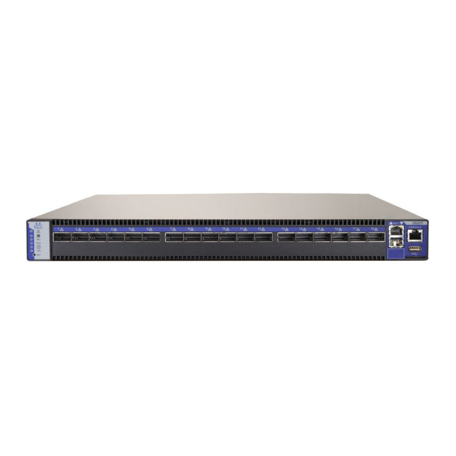
This manual is intended as a reference for technicians who dismantle Mellanox 1U top of the rack switch systems for WEEE recyclers. Mellanox Technologies emphasizes the importance of carefully following all procedures described in this guide to prevent personal injury. - Page 8 Supply, Short depth, Managed, Connector side to PSU side airflow, Rail Kit and RoHS6 MSX6018F-1SFS SwitchX®-2 based 18-port QSFP FDR 1U managed InfiniBand switch system with a non-blocking switching capacity of 2Tb/s. 1PS, standard depth, forward airflow, RoHS6 Mellanox Technologies Confidential...
-
Page 9: Policy Statement
Mellanox Technologies recognizes the importance of developing connectivity solutions that not only enable our customers to optimize their data centers performance, but also protect the environment and ensure that future generations enjoy its bounties. Mellanox Technologies is committed, therefore, to meeting the requirements of the European Union’s WEEE (waste electrical and electronic equipment) directive. -
Page 10: Dismantling Instructions
Switch systems are comprised of: 1. Main board 2. CPU board with battery –– Not found on unmanaged switches 3. Fan unit 4. Harnesses 5. Power Supply Unit (PSU) 6. Cover 7. Secondary boards Figure 2 – Switch Main Components Mellanox Technologies Confidential... -
Page 11: General Preparations
3. Remove the PSU. 4. Repeat the procedure for the second PSU if there is one. 5. If there is only one PSU, remove the blank cover. Figure 5 - Switch with 1 PSU/ 2 PSUs Removed Mellanox Technologies Confidential... -
Page 12: Fan Unit Extraction
These two latches must be pushed towards each other at the same time while the module is pulled out. Cover Extraction Unscrew all of the screws from the top and sides of the cover. Slide the cover to the power side and remove the cover. Figure 7 – Remove Cover Mellanox Technologies Confidential... -
Page 13: Battery Extraction -- Managed Switches Only
Figure 8 – Remove Battery Battery Front Panel Extraction Unscrew the 6 Philips screws attaching the panel itself to the switch, and the additional two screws connecting the LED board. Disconnect the LED board connector. Figure 9 - Front Panel Mellanox Technologies Confidential... -
Page 14: Harness Extraction
Disconnect the harness connections and remove harnesses from the base. Figure 10 - Harness Connections Secondary Boards Extraction Unscrew the Philips screws and remove screws and spacers to extract the secondary boards. Figure 11 – Secondary Boards Secondary Boards Mellanox Technologies Confidential... -
Page 15: Cpu And Main Board Extraction
Unscrew the Heat-sink screws to extract the Heat-sink. Unscrew the Philips screws and remove spacers to extract the CPU Board. Unscrew the Philips screws and remove spacers to extract the Main board. Figure 12 - Remove Heat Sink and Board Mellanox Technologies Confidential...
Need help?
Do you have a question about the MetroDX MTX6000-2SFS and is the answer not in the manual?
Questions and answers