Table of Contents
Advertisement
Quick Links
Advertisement
Table of Contents

Related Manuals for Grundig GU-RN-AC8104P


Summary of Contents for Grundig GU-RN-AC8104P
- Page 1 1 English...
-
Page 2: Table Of Contents
CONTENT 1 PRODUCT OVERVIEW .......................... 8 ............................ 8 ANEL 2 NVR INSTALLATION & CONNECTION ....................9 2.1 HDD I ..........................9 NSTALLATION 2.2 C .......................... 10 ONNECTION IAGRAM 2.3 P ........................10 OWER UPPLY ONNECTION 3 NVR COMMON OPERATIONS ......................11 3.1 U ........................ - Page 3 5.1.1.4 POE Power ............................32 5.1.2 Live ............................33 5.1.3 Image Control ..........................34 5.1.4 PTZ ............................. 35 5.1.5 Video Cover ..........................35 5.1.6 Motion ............................36 5.1.7 PIR ............................. 37 5.1.8 Deterrence ..........................38 5.1.9 Intelligent Analysis ........................39 5.1.9.1 PID (Perimeter Intrusion Detection) ....................
- Page 4 5.4.1.7 CD (Crowd Density Detection) ......................70 5.4.1.8 QD (Queue Length Detection) ......................71 5.4.1.9 Schedule ............................. 73 5.4.2 Recognition ..........................73 5.4.2.1 Model Configuration .......................... 73 5.4.2.2 Database Management ........................74 5.4.3 Alarm ............................76 5.4.3.1 Face Recognition ..........................76 5.4.3.2 AD (Attribute Detection) ........................
- Page 5 5.7.2 Multi-user ..........................117 5.7.2.1 Changing Password ........................... 118 5.7.2.2 Add New Users ..........................119 5.7.2.3 Setting User Permissions ........................119 5.7.3 Maintenance ........................... 120 5.7.3.1 Log ..............................121 5.7.3.2 Load Default ............................. 122 5.7.3.3 Upgrade ............................123 5.7.3.4 Parameter Management ........................123 5.7.3.5 Auto Reboot .............................
- Page 6 6.10.2 Human & Vehicle ........................157 6.10.3 PID &LCD ..........................158 6.10.4 Repeat Visitors ........................159 6.10.5 Face Attendance ........................161 7 REMOTE ACCESS VIA WEB CLIENT ....................162 7.1 B ..................162 ASIC YSTEM NVIRONMENT EQUIREMENTS 7.2 W ................... 162 LUGIN OWNLOAD AND NSTALLATION...
- Page 7 Introduction Thank you for purchasing a Grundig product. Before installing or connecting the product, please read first the following documents which you can find in printed form in the product package: - Legal Disclaimer - Safety Instructions - Installation Manual and/or Quick Guide for the respective product model Further information about the product like Data Sheets, CE Documents, etc.
-
Page 8: Product Overview
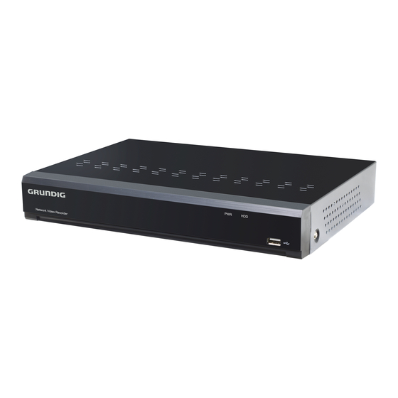
1 Product Overview 1.1 Rear Panel Item Physical Port Connection Method Power Switch Startup and shutdown Power Port Connect the attached power supply AUDIO OUTPUT Optional. Audio signal output, RCA interface VGA Port Connect to VGA monitor, such as PC monitor HDMI Port HDMI high-definition port USB Port... -
Page 9: Nvr Installation & Connection
2 NVR Installation & Connection 2.1 HDD Installation This NVR supports two 3.5” or 2.5” SATA hard disk drives. Note: DO NOT install or remove the hard disk drive while the device power is turned ON HDD Installation: b) Carefully flip the NVR case and secure the hard disk drives a) Connect the data and power cables to the two hard disk to the NVR with the eight (8) screws drives and place the hard disk drives on the NVR case. -
Page 10: Connection Diagram
2.2 Connection Diagram Speaker Note: Above diagram is for reference only. The practical connection may be different depending on the NVR you purchased. 2.3 Power Supply Connection Note: Use only the supplied power adapter that came with the NVR. Connect one end of the power adapter to the power connector on the back of the NVR. Plug the other end of the power adapter into the wall outlet. -
Page 11: Nvr Common Operations
3 NVR Common Operations 3.1 Using the Supplied Mouse Left Button: Click to select menu options. During live viewing in split-screen view, double-click on a channel to view it in full-screen. Double-click the channel again to return to split-screen viewing. Click upon a channel on Live Viewing screen to open Camera Quick Toolbar. -
Page 12: Password
3.3 Password For the first time when you run the NVR, you must be required to set your own password immediately in order to protect your privacy. Please be sure to record your username and password and save them in a secure place. Language: Choose an OSD language Device ID: Input the device ID in the parentheses. -
Page 13: Nvr Starting Up
4 NVR Starting up 4.1 Start Wizard Startup Wizard will help to configure the system and get the NVR works quickly. 4.1.1 Start Wizard Click the Start Wizard to proceed to the next step 4.1.2 Network Configuration If you connect to a router allows to use DHCP, please check the DHCP box. The router will assign automatically all the network parameters for your NVR. -
Page 14: Date/Time
Gateway: This address allows the NVR to access the Internet. The format of the Gateway address is the same as the IP Address. For example, “192.168.001.001”. IPv6 Address: Input the IPv6 address you got from your ISP. DNS1/DNS2: DNS1 is the primary DNS server and DNS2 is a backup DNS server. Usually should be enough just to enter the DNS1 server address. -
Page 15: Ip Camera
Date and Time Click on the calendar icon to set the current system date. Date: Click on the calendar icon to set the system date. Time: Click to set the system time. Date Format: Choose from the dropdown menu to set preferred date format. Time Format: Choose time format between 24Hour and 12Hour. - Page 16 For PoE NVR, the IP camera will get online automatically if the IP camera is connected to the PoE port on the NVR rear panel. Check more in 5.1.3.1 PoE NVR Connection For Non-PoE NVR, you need to add the IP cameras from LAN and/or Internet manually. Check more in 5.1.3.2 Non-PoE NVR Connection.
-
Page 17: Disk
4.1.5 Disk If the HDD is installed in the NVR for the first time, it must be formatted. Select the HDD and then click Format HDD button to format the HDD. Overwrite: Use this option to overwrite the old recordings on the HDD when the HDD is full. For example, if you choose the option 7 days then only the last 7 days recordings are kept on the HDD. -
Page 18: Summary
4.1.8 Summary You can check the system summary information you had set in the start wizard and finish the wizard. Tick “Don't show this window next time" if you don’t want to display Start Wizard when system reboot next time. Click Finish button to save & exit. 18 English... -
Page 19: Live View Screen Overview
4.2 Live View Screen Overview Status Icons This indicates that the NVR is currently recording. This icon appears when the camera has detected motion. The icon indicates that the external I/O alarm device is triggered This icon indicates that the HDD is in error to work This icon indicates the HDD is unformatted This icon indicates the HDD is full. - Page 20 Click to manually record the channel immediately. If the manually recording is in process, the icon will be in red color. Click one more time to stop manual record. Click to save a snapshot of the current camera image. Manual Capture must be enabled to use this feature.
-
Page 21: Taskbar
4.2.2 Taskbar Click to open the Start Menu Click to choose different layout for live view Click to choose more layouts for live view Click to start viewing channels in a sequence. You’re able to set the sequence display mode on 5.7.1.3 Output Configuration Quick playback. -
Page 22: Unlock And Lock Screen
4.2.3.1 Unlock and Lock Screen The screen will be locked to protect unauthorized OSD operation while the NVR is not in menu operation 1 minute. If necessary, you can also lock the screen operation manually. To do so, go to Star Menu, and then click the Lock Screen icon to lock the system immediately. -
Page 23: Nvr System Setup
5 NVR System Setup You are able to configure the NVR for Channel, Record, Alarm, Network, Device & System from Start Menu → Setup. 5.1 Channel In this section, you are allowed to configure the camera connection, live view display, manage IP cameras, adjust IP camera’s image, PTZ setup, Video Cover, Motion, and more. -
Page 24: Channel
5.1.1 Channel 5.1.1.1 Channel Config This menu doesn’t appear in all NVRs, which only appears when your NVR supports to connect wireless cameras. Maximum 4 wireless IP cameras are allowed to connected to the NVR. Click the drop-down arrow next to the channel ID and choose the mode. Choose “Digital” if you’re using a wired IP camera, chose “Wireless”... -
Page 25: Ip Channels
5.1.1.3 IP Channels In this section, you are able to configure the connection of your wired IP cameras. If your NVR comes with PoE ports, please go to 5.1.3.1 PoE NVR Connection, if your NVR comes without PoE port, please go to 5.1.3.2. - Page 26 Switch Mode: Auto mode limits the maximum bandwidth to 100Mbps, EPOE mode limits the maximum bandwidth to 10Mbps. If you have a connection problem with Auto mode when the IP camera is powered by PoE via a RJ45 cable longer than 100 meters, then change to EPOE mode for a stable connection.
-
Page 27: Steps To Connect Plug & Play Poe Cameras
Icon with green grey color: failed to connect camera. Click the icon to show the failure reason. If the failure reason is “User name or password error”, it means the camera user name and password is different from the default user name and password. If the failure reason is “Failed to connect to camera, please check the network connection”, it means the network parameter might be incorrect or incompatible ONVIF-protocol. -
Page 28: Steps To Connect External Cameras In The Lan
5.1.1.3.1.2 Steps to Connect External Cameras in the LAN If you want to connect to an IP camera from LAN, please make sure your NVR is well-connected to the LAN and the IP camera you want to add is in the same network segment with your NVR. If you want to all channels manually, click the drop-down arrow next to Switch Mode, and then select “Manual”. - Page 29 Or click the Add icon in the channel list to add a camera to an individual channel. Click Search button, all available cameras in the LAN will be displayed. 2. Select the camera you want to connect and then click button.
- Page 30 Or click Add All button, the NVR will search & add all available cameras in the LAN. 2. Select the cameras from the search result, and then click “Add”. You would need to input the user name and password of the cameras. Please make sure all the cameras you want to add use the same user name and password.
- Page 31 2. Click the edit icon and select the camera channels one by one or check the box to select all cameras. Click icon to go back to search list. 3. Select the NVR in the search list, and then click Add button. 4.
-
Page 32: Add Cameras From Internet
5.1.1.3.1.3 Add Cameras from Internet If your NVR is connected to internet, you’re able to add cameras from internet with WAN IP address. 1. Click Add button in the search page. 2. Input the IP address or domain name, port, protocol, user name & password of the IP camera. Click Add button to add the camera. -
Page 33: Live
5.1.2 Live To configure camera parameters, including channel name, color, date/time format, refresh rate, etc. Convert: To hide the camera images in live view. If the covert is opened, only live view images will be hidden. Recording image won’t be affected. Channel Name: Give a name to the camera Show Name: To display the channel name in the images. -
Page 34: Image Control
5.1.3 Image Control This menu allows you to control image settings for supported IP cameras. ONVIF IP camera might be not supported to configure. Setup: Click icon into the setup page. Choose a channel to Select the desired built-in IR cut filter mode to configure ensure the camera works properly both in the day and night. -
Page 35: Ptz
period, then choose “Schedule(B/W)”, and then set the start and end time. WDR/DWDR: Enable to allow automatically adjust the brightness and contrast of the video when shooting in the darkness with bright light sources. IR-LED / Supplement Light: Set the IR/Supplement lights on/off. 5.1.4 PTZ This menu allows to configure the PTZ (Pan-Tilt-Zoom) settings for the speed dome cameras. -
Page 36: Motion
Note: The area of privacy zones you had set will be invisible in both live view & recording video. 5.1.6 Motion This menu allows you to configure motion parameters. When motion has been detected by one or more cameras, your NVR will alert you to a potential threat at your home. It does this by sending you an email alert with an attached image from the camera to use as a reference (if this option is enabled) and/or sending push notifications via the mobile app. -
Page 37: Pir
Motion Detection Area: The whole screen is marked for motion detection (red blocks) as default. If you want to disable the motion detection on a certain area, click the grid cursor and then drag the mouse to highlight the scope to unmark the area into transparent blocks. -
Page 38: Deterrence
PIR Detection Area: The whole screen is marked for PIR detection (red blocks) as default. If you want to disable the PIR detection on a certain area, click the grid cursor and then drag the mouse to highlight the scope to unmark the area into transparent blocks. -
Page 39: Intelligent Analysis
When the time slot is marked light blue, this indicates the channel triggers deterrence alarm for that time slot. 5.1.9 Intelligent Analysis The optional intelligent Analysis functions, including PID (Perimeter Intrusion Detection), LCD (Line Crossing Detection), SOD (Stationary Object Detection), PD (Pedestrian Detection), FD (Face Detection), and CC (Cross Counting), SOD (Sound Detection) and Video Tampering. - Page 40 Channel: Select the channel you want to configure Rule Number: Max. 4 rules available. Rule Switch: Activate or inactivate the rule 1. Choose one of the Rule Number. It is the number of PID area. Maximum 4 areas you can set for PID function.
-
Page 41: Alarm Setup
5.1.9.1.1 Alarm Setup Click icon to configure alarm settings. In the page, you can configure the alarm action when an alert is triggered. Buzzer: Disable or to active the buzzer to emit an alarm tone in 10, 20, 40 or 60 seconds when the detection is triggered. -
Page 42: Lcd (Line Crossing Detection)
Picture to Cloud: To upload alarm images to cloud server when motion is detected. To enable Cloud, please view 5.6.2 Cloud. Video to Cloud: To upload alarm video to Cloud server when motion is detected. To enable Cloud, please view 5.6.2 Cloud. -
Page 43: Sod (Stationary Object Detection)
Rule Number: Max. 4 rules available. Rule Switch: Activate or inactivate the rule 1. Choose one of the Rule Number. It is the number of LCD lines. Maximum 4 lines you can draw. 2. To enable the detection in Rule Switch. 3. - Page 44 Switch: Check the box to enable SOD function. Sensitivity: Set the sensitivity level. Level 1 the lowest sensitivity level while level 4 is the highest sensitivity level. Click Setup icon to draw a virtual region in the camera image. Channel: Select the channel you want to configure Rule Number: Max.
-
Page 45: Fd (Face Detection)
For Alarm setup, please refer to 5.1.9.1.1 Alarm Setup 5.1.9.4 FD (Face Detection) Face Detection function detects the faces of moving people appear in a pre-defined region. Switch: Check the box to enable FD function. Click Setup icon to draw a virtual region in the camera image. Channel: Select the channel you want to configure Rule Switch: Activate or inactivate the rule... -
Page 46: Cc (Cross Counting Detection)
or drag the corners to resize the region. 5. If you want to remove one of the regions from the camera picture, click the red box in the region and then click Remove button. Click Remove All will delete all regions. For Alarm setup, please refer to 5.1.9.1.1 Alarm Setup 5.1.9.5 CC (Cross Counting Detection) -
Page 47: Sd (Sound Detection)
number. 3. Use your mouse to click 2 points in the camera picture to draw a virtual line. 4. Click Save to save your settings. 5. If you want to modify the position or length of the line, click the red box in the line, the color of the line will be changed to red color. -
Page 48: Video Tampering
5.1.9.7 Video Tampering Video Tampering detects the occlusion of the live view screen, and some certain actions can be taken when the alarm is triggered. Switch: Enable or disable the VD function Sensitivity: The sensitivity level is from 1 to 6, with a default value of 3. Higher sensitivity will be easier to trigger the detection. -
Page 49: Cross Counting Statistics
5.1.9.9 Cross Counting Statistics The statistical result can be queried by Daily / Weekly / Monthly / Annual for Cross in & Cross Out. 5.2 Record This menu allows you to configure the recording parameters. 5.2.1 Encode This menu allows you to configure the recording video or network transmission picture quality. Generally, Mainstream defines the recording video quality which will be saved in the HDD;... -
Page 50: Record
FPS: This parameter defines the number of frames per second the NVR will record. Video Encode Type: H264/H.265. Some cameras might be supported MJPEG. Bitrate Control: Select the bitrate level. For a simple scene, such as a gray wall is suitable constant bitrate (CBR). -
Page 51: Capture
the cursor to mark the slots. The recording schedule is valid only for one channel. If you want to use the same recording schedule for other channels, use Copy function. Channel: Select the channel to set its recording parameters. Normal: When the time slot is marked green, this indicates the channel performs normal recording for that time slot. -
Page 52: Capture
5.2.3.1 Capture Enable Capture: Enable or disable automatic capturing on the channel. Stream Type: Select the image resolution by mainstream or substream. Normal Interval: Time interval to capture an image in normal recording. Alarm Interval: Time interval to capture an image when motion, IO alarm or PIR is triggered Manual Capture: Enable or disable manual capture in the channel 5.2.3.2 Capture Schedule Channel: Select the channel to set its capture parameters. -
Page 53: Alarm
Motion: When the time slot is marked yellow, this indicates the channel capture images when a motion is detected during that time slot. IO: When the time slot is marked red, this indicates the channel capture images when the sensor is triggered during that time slot. -
Page 54: Pir
Video to Cloud: To upload alarm video to Cloud server when an alarm is triggered. To enable Cloud, please view 5.6.2 Cloud. Full Screen: If this function is enabled and an alarm is triggered in a channel, you will see its full screen images in live view. -
Page 55: I/O
Video to Cloud: To upload alarm video to Cloud server when an alarm is triggered. To enable Cloud, please view 5.5.2 Cloud. Full Screen: If this function is enabled and an alarm is triggered in a channel, you will see its full screen images in live view. -
Page 56: Intelligent
Send Email: Set to send email to specified email when sensor is triggered. Full Screen: When sensor is triggered, the corresponding channel will be switched to the full screen mode. FTP Picture Upload: To upload alarm images to FTP server when an alarm is triggered. To enable FTP, please view 5.4.4 FTP. -
Page 57: Ptz Linkage
Alarm Out: Optional function. If your NVR support to connect to external alarm device, you can set to emit an alarm tone. Latch Time: To configure the external alarm time when an alarm is triggered. Record: Click icon and choose which channel(s) you want to record when an alarm is triggered. Post Recording: You can set how long after an event occurs that the NVR will continue to record. -
Page 58: Exception
Switch: Enable or disable the PTZ linkage function. Motion: Motion detection alarm will trigger the PTZ linkage function it is checked. IO: IO alarm will trigger the PTZ linkage function it is checked. PIR: PIR alarm will trigger the PTZ linkage function it is checked. 5.3.6 Exception This menu allows you to set the type of events that you want the NVR to inform you. -
Page 59: Alarm Schedule
5.3.7 Alarm Schedule In this menu, you can set several schedules, including Alarm out, Push, FTP Upload, Cloud Upload and Buzzer. Channel: Select the channel to set its capture parameters. To set the schedule, choose one channel and one of the alarm types then drag the cursor to mark the slots. - Page 60 Local Conversion: The system supports to convert your plain text into audio file by local algorithm. Choose Local Conversion Models, and then input the name of the file & plain text. Click Import button, the system will convert the text you input into a voice file and save to the NVR storage. Internet Server Conversion:The system supports to convert your plain text into multi-language audio file by internet server.
-
Page 61: Setup
It is recommended to operate with webpage for multi-language input except for English. 5.4 AI You will see this section if your NVR has capacity for AI. The NVR will support to realize AI functions including FD (Face Detection), PD & VD (Human & Vehicle Detection), PID (Perimeter Intrusion Detection), LCD (Line Crossing Detection), CC (Cross Counting), HM (Heat Map), CD (Crowd Density Detection) and QD (Queue Length Detection) with AI powered IP cameras. - Page 62 Channel: Channel selection Snap Mode: There are “Optimal Mode” (automatically select & push the best image from all face images of the same person whose faces were captured during his/her duration of stay), “Realtime Mode” (push the first captured face image and push again the last captured face image from the same person) and “Interval Mode”...
-
Page 63: Pd & Vd (Human & Vehicle Detection)
Max Pixel: Set the maximum detection pixel box. The face can be recognized only when it is smaller than the pixel box. Face Enhance: Face enhancement makes it easier to recognize the moving faces, but it may lower the whole picture quality. Face Attribute: Enable this function to detect mask, glasses and facial expression. - Page 64 Switch:To enable or disable the Human & Vehicle detection. Click to configure the detection conditions. Channel: Channel selection Snap Mode: There are “Optimal Mode” (automatically select & push the best image from all captured images of the same vehicle during its duration of stay), “Realtime Mode” (push the first captured image and push again the last captured image from the same vehicle) and “Interval Mode”...
-
Page 65: Pid (Perimeter Intrusion Detection)
5.4.1.3 PID (Perimeter Intrusion Detection) Perimeter Intrusion Detection function detects people, vehicle or other objects which enter and loiter in a pre-defined virtual region, and some certain actions can be taken when the alarm is triggered. Switch:To enable or disable the Perimeter Intrusion Detection. Click to configure the detection conditions. -
Page 66: Lcd (Line Crossing Detection)
6. Click Save to save your settings. 7. If you want to modify the position or sharp of region, click the red box in the region, the borders of the region will be changed to red color. Click and hold the left button of your mouse to move the position of the region, or drag the corners to resize the region. - Page 67 Channel: Select the channel you want to configure Detection Type: Choose the detection target objects. Rule Number: Max. 4 rules available. Rule Switch: Activate or inactivate the rule Dynamic Marking:If you enable this option, the border of the detection zone will be displayed in both live view images and recording files.
-
Page 68: Cc (Cross Counting)
5.4.1.5 CC (Cross Counting) Cross Counting function counts the times for moving objects or people across the virtual lines. Switch: Check the box to enable the function. Sensitivity: Set the sensitivity level. Level 1 the lowest sensitivity level while level 4 is the highest sensitivity level. -
Page 69: Hm (Heat Map)
Start Time: Set the detection start time. End Time: Set the detection end time. Reset Count: Clear the counting number. Rule Number: Only 1 rule available. Rule Switch: Activate or inactivate the rule. 1. Choose the detection target type. 2. Set the Alarm Number, Start Time and End Time. 3. -
Page 70: Cd (Crowd Density Detection)
1. To enable the detection in Rule Switch. 2. Use your mouse to click 4 points in the camera picture to draw a virtual region. The sharp of the region should be a convex polygon. Concave polygon will be not able to save. 3. -
Page 71: Qd (Queue Length Detection)
Min Pixel: Set the minimum detection pixel box. The people can be recognized only when he/she is larger than the pixel box. Max Pixel: Set the maximum detection pixel box. The people can be recognized only when he/she is smaller than the pixel box. Max Detection: The NVR will send an alert if the number of people inside the detection area exceeds the Max Detection number. - Page 72 Switch: Check the box to enable the QD function. Sensitivity: Set the sensitivity level. Level 1 the lowest sensitivity level while level 4 is the highest sensitivity level. Click Setup icon to configure the detection conditions. Min Pixel: Set the minimum detection pixel box. The people can be recognized only when he/she is larger than the pixel box.
-
Page 73: Schedule
camera picture to draw a virtual region. 7. Click Save to save your settings. 8. If you want to modify the position or sharp of region, click the red box in the region, the borders of the region will be changed to red color. Click and hold the left button of your mouse to move the position of the region, or drag the corners to resize the region. -
Page 74: Database Management
5.4.2.2 Database Management You’re able to create the face database to classify different faces. There are 3 default groups: Allow List, Block List and Stranger. You can use add icon and delete icon to add or delete customized groups. Import Database: Import database from USB memory. Backup Database: Export database to USB memory. - Page 75 Choose the start time and end time manually. Or you can select the time interval from 1 day, 2 days, 3 days, 4 days, 5 days, 6 days, 1 week and 1 month, and then click the button to move to left or right period.
-
Page 76: Alarm
Use the same method to add face images from external USB storage devices. 5.4.3 Alarm To configure the alarm action when an AI alert happens. 5.4.3.1 Face Recognition To configure alarm actions for different face groups when faces detected. Enable Alarm: To enable or disable the alarm function. Policy: To set the group to be Allow list or Deny list. - Page 77 Buzzer: The NVR can use its internal buzzer to emit an alarm tone. You can set the buzzer duration in seconds when an alarm is triggered. Alarm Out: Optional function. If your NVR support to connect to external alarm device, you can set to emit an alarm tone.
-
Page 78: Ad (Attribute Detection)
Channel: Select the channel to set its capture parameters. To set the schedule, choose one channel then drag the cursor to mark the slots. The blue blocks in the time slots will be active for alarm. The schedule is valid only for the selected channel each time when you set. -
Page 79: Pd & Vd (Human & Vehicle Detection)
Post Recording: You can set how long after an event occurs that the NVR will continue to record. The recommended recording length is 30 seconds but it can be set higher up to 5 minutes. Show Message: Check the box to display “S” icon on the live view screen when the alarm is triggered. Send Email: You can let the NVR to send you an auto-email when an alarm is triggered. -
Page 80: Pid (Perimeter Intrusion Detection)
Picture to Cloud: To upload alarm images to Cloud server when an alarm is triggered. To enable Cloud, please view 5.5.2 Cloud. Full Screen: If this function is enabled and an alarm is triggered in a channel, you will see that channel in full screen. -
Page 81: Lcd (Line Crossing Detection)
Full Screen: If this function is enabled and an alarm is triggered in a channel, you will see that channel in full screen. Voice Prompts: If your NVR or IP camera connects with a speaker, you can select an customized alert voice when the alarm happens for different time period. -
Page 82: Cc (Cross Counting)
Voice Prompts: If your NVR or IP camera connects with a speaker, you can select an customized alert voice when the alarm happens for different time period. See how to add customized alert voice on 5.3.8 Voice Prompts. 5.4.3.6 CC (Cross Counting) To configure alarm actions for CC alarms. -
Page 83: Cd (Crowd Density Detection)
5.4.3.7 CD (Crowd Density Detection) To configure alarm actions for CD alarms. Buzzer: The NVR can use its internal buzzer to emit an alarm tone. You can set the buzzer duration in seconds when an alarm is triggered. Alarm Out: Optional function. If your NVR support to connect to external alarm device, you can set to emit an alarm tone. -
Page 84: Qd (Queue Length Detection)
5.4.3.8 QD (Queue Length Detection) To configure alarm actions for QD alarms. Buzzer: The NVR can use its internal buzzer to emit an alarm tone. You can set the buzzer duration in seconds when an alarm is triggered. Alarm Out: Optional function. If your NVR support to connect to external alarm device, you can set to emit an alarm tone. -
Page 85: Statistics
5.4.4 Statistics You are able to check and manage the statistics of AI functions in this section. 5.4.4.1 FD (Face Recognition) You can check the face recognition statistics in a certain period. 1 . Choose the group(s) and channel(s). 2. Select the period from day, week, month, quarter and year. 3. -
Page 86: Cc (Cross Counting)
1. Choose the detection type in Intelligent. 2. Choose the channel(s). 3. Select the period from day, week, month, quarter and year. 4. Click the calendar icon to choose the date, and click button to move to last or next period. 4. -
Page 87: Network
1. Choose the channel & date. 2. Choose the Report Type: Daily, Weekly, Monthly or Annually. 3. Choose the Cross Type: Cross In or Cross Out. 4. Click Search button, the result will be displayed in either Column Chart or Line Chart. 5. -
Page 88: Pppoe
If you connect to a router allows to use DHCP, please check the DHCP box. The router will assign automatically all the network parameters for your NVR. Unless the network is manually addressed below parameters: IP Address: The IP address identifies the NVR in the network. It consists of four groups of numbers between 0 to 255, separated by periods. -
Page 89: Port Configuration
5.5.1.3 Port Configuration Web Port: This is the port that you will use to log in remotely to the NVR (e.g. using the Web Client). If the default port 80 is already taken by other applications, please change it. Client Port: This is the port that the NVR will use to send information through. If the default port 9000 is already taken by other applications, please change it. -
Page 90: Email
Domain: Enter the domain name you created on the DDNS service provider’s web page. This will be the address you type in the URL box when you want to connect remotely to the NVR via PC. Fox example: NVR.no-ip.org. User/Password: Enter the user name and password you obtained when creating an account on the DDNS service provider’s web page. -
Page 91: Email Schedule
Encryption: Enable if your email server requires the SSL or TLS verification. If you are not sure, set to be Auto. SMTP Port: Enter the SMTP port of your email server. SMTP Server: Enter the SMTP server address of your email. User Name: Enter your email address. -
Page 92: Ip Filter
FTP Enable: Click to enable FTP function. Server IP: Enter your FTP server IP address or domain name. Port: Enter the FTP port for file exchanges. Name/ Password: Enter your FTP server user name and password. Directory Name: Enter the default directory name for the FTP file exchanges. Test FTP: Click to test the FTP settings. -
Page 93: Voice Assistant
If you want to activate this function, check the Enable box. Choose either Enable Allow List or Enable Block List. Allow List will only allow those IP address in the list to visit the NVR. Block List will block those IP address in the list to visit the NVR. Choose one of the Restricted Types you want to set. - Page 94 2. Go to Channel – Live menu, and give a Channel Name which is easy to call to the channel(s) you want to cast to your TV monitor. 3. Connect the Fire TV Stick to your TV monitor, and power on it. Connect the Fire TV Stick to the Wi- Fi which is in the same LAN with your NVR.
- Page 95 6. Search cand install Amazon Alexa to your mobile phone from app store, and then login with the Amazon account which is same as the one you bind to the NVR. 6. Touch “More”, and then touch “Skills & Games”. 95 English...
- Page 96 7. Touch the search icon on the right top corner. 8. Input the keyword: smart camera view, and search. 96 English...
- Page 97 Touch the “Smart Camera View” in the search result list. Touch “ENABLE TO USE”. 97 English...
- Page 98 9. You would need to link your Amazon account. Sign in the Amazon account which is same as the one you bind to the NVR. Touch “Done” after the skill is successfully linked. 10. Touch “DISCOVER DEVICES” and wait a moment for the app to search the cameras. Touch Next when the devices were found and connected.
- Page 99 11. Choose one of the devices and then touch SET UP DEVICE. You can add the camera to a group or skip. 12. Repeat setup 11 to add all cameras and then touch Done to finish. 99 English...
- Page 100 13. All added cameras will be listed in the Devices. Touch the Cameras icon to check all added cameras. 14. Press and hold on the voice button on the remote controller of the fire TV stick, and speak the command clearly. The command could be like: Show the XXX camera / Show XXX. XXX is the camera channel name.
-
Page 101: Voice Assistant With Google Chromecast
15. Wait for a while, you will see the real time images from the Office camera in your TV monitor. 16. If you want to quit the camera live view, speak “Stop”. 17. If you have changed the channel name, you would need to discover and add the camera again. 5.5.6.2 Voice Assistant with Google Chromecast 1. - Page 102 3. Connect the ChromeCast to your TV monitor, and power it on. 4. Search and install Google Home app to your mobile phone from app store. Run the installed Google Home app, touch OK to allow the app to use your local network and Bluetooth and then touch Get Started.
- Page 103 To allow location access for the app. 7. The app will automatically try to search devices from your local network. Choose Chromecast / Google TV. Make sure your Chromecast is turned on already, then touch Next. 103 English...
- Page 104 8. Your Chromecast will be found. Touch Next to connect. Confirm the code by touching Yes. 9. Choose a location for your Chromecast, then touch Next. 104 English...
- Page 105 10. Choose the Wi-Fi network for your Chromecast and input the Wi-Fi password to connect. Make sure the Wi-Fi you choose is the same one with your mobile phone and is in the same local network with your NVR. Touch Continue to next step. 11.
- Page 106 12. Now the Chromecast has been added to your Google Home. Touch the + icon on the left top corner. Indoor, then choose Set up device. Choose “Work with Google”, touch the search icon on the right top corner and then input “smart camera view”.
- Page 107 Touch on “Smart Camera View” in the search result. You would need to sign in your google account and allow the Google to access to your device. Wait for a while, the Smart Camera View application will be linked to the Google Home. 13.
- Page 108 14. Repeat step 13 to add all cameras. 13. Search and install Google Assistant app to your mobile phone from app store. 14. Run the Google Assistant, login your google account which is same as the one you bind to the NVR.
-
Page 109: Platform Access
5.5.7 Platform Access This function is mainly used to connect 3 party platform, like ECMS/NVMS via ONVIF protocol. Enable:Check to enable this function. Authentication:Login authentication type, options including Digest_sha256, Digest, Digest/WSSE, WSSE and None. Choose one of them to match to your 3 party platform. -
Page 110: Disk
5.6.1 Disk This menu allows you to check & configure the internal HDD(s). You need to format the HDD only at the first startup and if you replace a new HDD. Format HDD: Select the HDD you want to format and then click Format HDD. To start formatting, you need to enter your user name and password and then click OK to confirm to continue formatting. -
Page 111: 111
5.6.1.1 S.M.A.R.T This function can be used to display technical information on the hard drive installed inside your NVR. You can also perform a test (there are three types available) to evaluate and detect potential drive errors. Whole Evaluation not passed, continue to use the disk: If for some reason the hard drive has developed a fault (such as one or more bad sectors), you can instruct your NVR to continue saving to the drive. - Page 112 Cloud Type: To choose Dropbox or Google Drive. Cloud Overwrite: Use this option to overwrite the old recordings on the storage when it is full. For example, if you choose the option 7 days then only the last 7 days recordings are kept on the storage. To prevent overwriting any old recordings, select OFF.
- Page 113 Input the DVR local IP address and web port, and then click Authorize. Input the DVR user name and password and then click OK. 10. Authorization finished; the webpage will turn to your Dropbox. 113 English...
-
Page 114: System
11. The Cloud has completed the setup if you find a new folder named by your NVR device name and MAC address in the Dropbox storage. Your alarm pictures and videos will be upload to this folder. 5.7 System Change general system information such as date, time and region, edit passwords and permissions, and more. -
Page 115: Date And Time
Menu Timeouts: Click the drop-down menu to select the time your NVR will exit the Main Menu when idle. You can also disable this by selecting “OFF” (password protection will be temporarily disabled). Show Wizard: Click the checkbox if you would like to display the Startup Wizard each time you turn on or reboot your NVR. - Page 116 Check to enable the NTP, and select a Server Address, click Update Now to manually sync the date & time. Click Apply to save your settings. When NTP function is enabled, system will update the system time at 00:07:50 per day, or every time when the system is starting up.
-
Page 117: Output Configuration
Date: Select the start date (click the calendar icon), end date and time when Daylight Saving starts and ends. Start Time / End Time: Set the start time and end time for Daylight Saving. 5.7.1.3 Output Configuration This menu allows you to configure video output parameters. Video Output: To choose the output options: SEQ Mode: To choose the display layout when you display the live view cameras in sequence. -
Page 118: Changing Password
The system supports the following account types: • ADMIN — System Administrator: The administrator has full control of the system, and can change both administrator and user passwords and enable/disable password protection. • USER — Normal User: Users only have access to live viewing, search, playback, and other functions. -
Page 119: Add New Users
5.7.2.2 Add New Users Select one of the user accounts that is currently disabled, click the User Edit icon Select Enable from the drop-down next to User Enable. Click the field next to User Name to change the user name for the account. Select Enable from the drop-down next to Password Enable. -
Page 120: Maintenance
1. Click the edit icon under Permission tab. 2. Check the boxes next to any system menus or capabilities you would like the user to access. Click All to check all boxes. Click Clear to check none of the boxes. 3. -
Page 121: Log
5.7.3.1 Log The system log shows you important system events, such as motion alarms and system warnings. You can easily create a backup file of the system log for a set time period to a USB flash drive. Log Searching and Backing Up: 1. -
Page 122: Load Default
3. Select the type of events you would like to search for from the dropdown next to Log Type, or select All to see the entire system log for the selected time period. 4. Click Search. 5. Browse system log events from your search period: Video events can be played back instantly by clicking in the Playback column. -
Page 123: Upgrade
5.7.3.3 Upgrade 1. Copy the firmware file (.sw file) to your USB drive, and insert the USB flash drive into the NVR’s USB port. 2. Click Select File button to choose the firmware file in your USB flash drive, then Click OK. 3. -
Page 124: Auto Reboot
5.7.3.5 Auto Reboot This menu allows the system to auto reboot the NVR regularly. It is recommended to leave this function enabled, as it maintains the operational integrity of your NVR. Auto Reboot: Check to enable. Time: You can set the NVR to reboot by day, week or month. 5.7.3.6 Developer Mode This menu will allow to collect some debug information for professionals to analyze the system situation. -
Page 125: Upgrade Ip Camera
5.7.4.1 Upgrade IP Camera This menu allows you to upgrade the IP camera’s firmware. 1. Choose one of the IP cameras you want to upgrade firmware. 2. Click Select File select the update file from your USB flash drive, then click OK. 3. -
Page 126: Load Default Settings For Ip Camera
5.7.4.2 Load Default Settings for IP Camera 1. Choose the IP cameras you want to restore. 2. Click Load Default to restore settings. You will be required to input the Admin password to authenticate. 5.7.4.3 Reboot IPC To reboot the IP camera you select. 126 English... -
Page 127: Parameter Management
5.7.4.4 Parameter Management Select the IP camera, click Save Settings to export its setting values to your USB memory. Select the IP camera, click Load Settings to import setting values from your USB memory. 5.7.5 System Information This menu allows you to view the system information, channel information, record information & network status. -
Page 128: Channel Information
5.7.5.2 Channel Information View channel information for each connected camera such as alias, mainstream and substream recording specifications, motion detection status & privacy zone. 5.7.5.3 Record Information View recording information for each connected camera such as bitrate, stream type, recording resolution and frame rate (FPS). -
Page 129: Ai Scenario
5.8 AI Scenario AI Scenario function provides AI applications for different specific scenarios. Click the submenu title in the main setup page to get into the individual function setup page. 5.8.1 Cross Counting This is an AI application based on cross counting function, which helps to control the attendance number of customers/visitors/vehicles in public places, like restaurants, parks, zoos, theaters, museums, car parks, etc. - Page 130 1. Navigation bar on the left side: Channel View Mode: To count and view the real-time result by individual camera(s). Mostly used for small place with single entrance & exit. Group View Mode: To count and view the real-time result by group(s). Mostly used for big place with multiplex entrances &...
- Page 131 Available: Remaining allowed attendance number Inside: Current attendance number inside the control area Enter: Recorded number of the total entrants Exit: Recorded number of the total leaving attendance. If the available number is more than 0, the carton figure will be in green color. If the available number is 0, the carton figure will be in red color.
-
Page 132: Channel View Setup
The all-day counting statistical data of all activated channels will be displayed here. Use the mouse wheel to move the timeline toward left or right. 5.8.1.1 Channel View Setup Click the add icon or setup icon to get to the configuration page. To enable the channel(s) you want to realize the counting function in the Channel list. - Page 133 Click one of the Setup icons to configure the detection conditions. Switch: Activate or inactivate the detection. Type: Choose the detection target objects. Motion will detect all moving objects, Person will detect human beings only, Vehicle will detect vehicles only. Sensitivity: Set the sensitivity level.
-
Page 134: Group View Setup
to move the line, or drag the terminals to modify the length or position of the line. ix. If you want to remove one of the lines from the camera picture, click the red box in the line and then click Remove button. x. - Page 135 will be not allowed to add to any group. Check the Enable box to activate the group. Set the Capacity number, Start Time, End Time of each group. Choose the detection target Type from Person, Vehicle and Motion. Click one of the Alarm icons to configure the alarm actions when the Available number is 0.
-
Page 136: Advertise Mode
You can choose which group you want to view the real-time live images and counting data. 10. Furthermore, it supports to display the counting data in Map mode. Click the Map button to configure the settings. 11. Click the icon to add a map image from your USB memory. 12. - Page 137 Check the Advertise mode in the Click Image button to load advising pictures from your USB memory. It supports to add maximum 16 pictures with jpg, png and bmp format, and the maximum resolution should be no more than 2560x1600. Click the add icon to add new picture(s) and click delete icon to delete the added picture one by one.
-
Page 138: Search Counting Data
5.8.1.4 Search Counting Data Click the Search icon to search the counting data. It is allowed to search separately for Channels and Groups. Choose the channel(s) or group(s) you want to search, set the search duration by day, by week, by month or by year and choose the target type you want to search. -
Page 139: Face Attendance
5.8.2 Face Attendance Face Attendance is an AI application based on Face Detection. You’re able to view and check the real- time statistical data of attendance management visually. 1. Custom title. 2. Overall attendance statistical data of all selected groups. 3. - Page 140 5. Push notifications of latest persons who have checked the attendance, including the Name/ID of the person, captured face image, group, clock in time and clock out time. Normal clock in & clock out time will be displayed in green color. Abnormal clock in & clock out time will be displayed in red color. Click the screen split icons to change the display layout.
- Page 141 141 English...
-
Page 142: Search, Playback & Backup
6 Search, Playback & Backup The Search function gives you the ability to search for and play previously recorded videos as well as snapshots that are stored on your NVR’s hard drive. You have the choice of playing video that matches your recording schedule, manual recordings or motion events only. - Page 143 Fast Forward, x2, x4, x8 and x16 Digital Zoom: Click to zoom in then click-and-drag on a camera image during playback to zoom in on the selected area. Right-click to return to regular playback. Video Clip. Quickly save a section of video to a USB flash drive. View more on 6.1.1.1 Video Clip Backup Save Video Clip.
-
Page 144: Search & Play Video In General
6.2 Search & Play Video in General This menu gives an option to search & play recording for a selected date. 1. Select a date to search for video recording from the calendar. 2. Choose a search type. 3. Check channels you would like to search, or check Channel to search all connected channels. 4. -
Page 145: Event Search, Playback & Backup
5. Move the mouse cursor to the timeline where you want to start the video clip. 6. Press and hold the left button of your mouse, and drag the drag the cursor to the timeline where you want to end the video clip. 7. - Page 146 To search, play & back up for events: 1. Choose the date & time you want to search. 2. Check the recording types you want to search, or check Search Type to choose all. 3. Choose the channels you want to search, or check Channel to choose all channels. 4.
- Page 147 7. You can switch the view of list form in by clicking below icons which is show at the right bottom corner of the screen: Thumbnail view. You can view the snapshots of the events. List view. The events will be displayed in list. Detailed view.
-
Page 148: Event Playback Control
6.3.1 Event Playback Control 1. Event List, you can select the events here. 2. Click icon to save your selected event videos to USB flash drive. Click icon to play video. 3. Control the playback with buttons on Video Playback Controls. You can click icon or click right button of your mouse to exit the playback and return to event search window. -
Page 149: Sub-Periods Playback
6.4 Sub-periods Playback Sub-periods playback allows you to play multiple normal recordings and motion events simultaneously from a single channel. With normal and event recordings, the video is divided evenly depending on the split-screen mode that has been selected. For example, if the video is an hour long and you have selected Split-screens x 4, each split-screen will play for 15 minutes. -
Page 150: Smart Search
9. Add Tag function: click to add customized tag, click to add default tag, enable to make mark in the current channel current time point. After adding, in tag playback page it will be able to jump to the “Tag” point playin g. 6.5 Smart Search With Smart search function, you will be able to quickly search and play the motion recording videos which were triggered by human beings. -
Page 151: Tag Search
: select whole image. : clear your selection. : go back to playback interface. : search. Click button to clear all selection, and then use your mouse to select the certain areas you want to search in the image. Click button, the system will search the display the smart search result for the selected areas. -
Page 152: Picture Search & View
Insert your USB memory into the USB port, find out the folder where the video files are saved, and then click the play icon to play the video. 6.8 Picture Search & View This function can be used to search, play and copy snapshots to a USB flash drive. To search, play &... - Page 153 5. Pictures fitting your search criteria are displayed in list form. You can double click one of the pictures to get a larger view. 6. Click icons in the bottom-right corner of the menu to browse between pages of pictures, or input the page you want to browse. 7.
-
Page 154: Picture Preview Control
6.8.1 Picture Preview Control 1. Picture List: to select pictures here. 2. Click button to save your selected pictures to a USB flash drive. 3. Press button to exit preview control window and go back to picture search window. Press button to pause, press to resume slideshow. -
Page 155: Ai Search
Choose the video stream type, channel, date and hour. The system will display 60 thumbnail images of each minute on the screen. Click on any one of the thumbnail images, the video will be played on the left bottom corner. 6.10 AI Search 6.10.1 Face Choose date, time, channel, groups to search all captures faces. - Page 156 Click Load Map button to load a map image from your USB memory. Check the Edit box. Click and hold the channel icon and move one by one to adjust the site of your IP cameras on the map. Uncheck the Edit box to quit the edition. Click icon to select one face image from local storage or external USB storage.
-
Page 157: Human & Vehicle
Click upon one of the sites, it will display the captured date & time. Click the Play button, the recorded video will be played on the left bottom corner. Click the play button on the play control, the system will automatically demonstrate the moving track. -
Page 158: Pid &Lcd
Select the date & time, channel(s). Choose the detection type: Human and/or Vehicle. Click Search, the result will be displayed on the right side of the window. Click one of the images, the system will show its basic information on the left side of the window, and the video will be played on the left bottom side. -
Page 159: Repeat Visitors
Select the date & time, channel(s). Select PID and/or LCD in Vigilance. Choose the detection type: Human and/or Vehicle. Click Search, the result will be displayed on the right side of the window. Click one of the images, the system will show its basic information on the left side of the window, and the video will be played on the left bottom side. - Page 160 Select the date & time, group(s) & channel(s). Set the Attributes. Set the Min. Interval time (second). Click Search, the result will be displayed on the right side of the window. You can sort the result by Time and Frequency. You can narrow the result by setting the Minimum Occurrence number.
-
Page 161: Face Attendance
6.10.5 Face Attendance Face Attendance is used to assist in attendance checking by faces. It will help to analyze the absenteeism, coming late and leaving early. Note: In case of failure, do NOT take the face attendance function as your only measure to check attendance. -
Page 162: Remote Access Via Web Client
7 Remote Access via Web Client Use the Web Client to remotely access your NVR at any time via a PC. Before you access the Web Client, you need to ensure that the internet settings of the NVR are configured properly. 7.1 Basic System Environment Requirements The minimum requirements for hardware and OS required to run Web Client are given as below. - Page 163 3. After installing the plug-in, close & launch again your browser and repeat step 1 to open the login page. Input your user name and password to login the web client. Note: For Microsoft Edge, Firefox, Google Chrome, Mac Safari, you don’t need to install the plug-in, but some functions might be limited.
-
Page 164: Web Client Manager
7.3 Web Client Manager The web client supports to fully control the NVR with administrator account. Please make sure to protect your user name & password for preventing illegal login. 7.3.1 Live Interface This is the first screen that opens after you have logged in to the Web Client. Here you can open or close live preview, record video to local computer manually, take snapshots of the screens, PTZ control, color adjustment, etc. - Page 165 2- Live Video Stream Options: Mainstream: View all live videos using high-quality mainstream video settings. Substream: View all live videos using middle-quality substream video settings. Mobile Stream: View all live video using lower-quality mobile stream video settings to conserve bandwidth. Available for IP channels only. 3- Main Menus: Live: View live video from cameras.
- Page 166 PTZ Controls Directional Arrows: Click to move the PTZ camera Automatic line scan. PTZ Speed: Click to set the speed of the PTZ camera’s movement. Zoom: Click –/+ to zoom in or out. Focus: Click –/+ to adjust focus. Iris: Click –/+ to adjust iris. Preset Point: Add, remove, or go to preset point.
-
Page 167: Playback
7.3.2 Playback You can search & play recording videos stored in the HDD inside the NVR, and download the videos to your computer. To search recordings: 1. Click Playback in the top-right corner of the window. 2. Select a day on the calendar to search for recordings from. Days with recordings appear with a red underline. -
Page 168: Playback Control Buttons
7.3.2.1 Playback Control Buttons Play the recordings Pause Stop Go Forward One Frame: Move frame-by-frame through playback. Only available when the Synchronous playback option is not checked. Click upon one of the channels which is being played and then click record button to record current video to your computer. -
Page 169: Remote Setting
Choose the files you want to download, press Start Download button to begin, you will see the download status. Press Stop Download button to stop. Playback Speed. Click to choose the playing speed. Play All Channels: Click to play all channels you have chosen to searched. Only available when the Synchronous playback option is not checked. - Page 170 Record Path: Click to browse for and select the folder where you would like the manual video recordings to be saved on your computer. Download Path: Click to browse for and select the folder where you would like to save the download video recordings to your computer.
-
Page 171: Viewing Backed Up Video On Pc
256MB RAM • 16MB video memory Install the Grundig Video Player software and run. 2. Copy the backup files to your computer. 3. Click Open File button or click button on the Play List to load single or multiple video files. It supports to add &... - Page 172 Video Player Control 1. Play List Add files Remove files To choose play mode: play a single file and stop; play all listed files by sequence; repeat one file; repeat all files. Filter by file name Hide/Show Playlist Click to open files or load a folder. 3.
- Page 173 Take snapshot To save a video clip to your computer. Press once to start, press again to end the video clip. Keep the video player on top Enlarge the video play screen to full screen Advanced Setup Menu allows to choose the OSD language of the video player, and configure the setting of video player.
-
Page 174: Remote Access Via Mobile Devices
9 Remote Access via Mobile Devices The NVR supports to remote access via mobile devices based on Android & iOS operating system. Search XCMS from Google Play Store for android devices or App Store for iOS devices and install. Run the app, and create an account. Log in with your credentials the GUI is displayed as below: Touch the icon in the middle to add a device. - Page 175 Enter a name for the device, now it is listed in your device list. Click onto the camera or NVR icon to get the live view. Click onto the icon which will open the settings for the device. 175 English...
- Page 176 If your device has an SD-card or HDD installed you can start the playback of events by pressing the playback button. If you click onto the icon you can filter between the event sources. A list of event sequences will be displayed then. To share a device with another user you can do this on the page Account in the option Share.
-
Page 177: Appendix
10 Appendix 10.1 Troubleshooting Q: What can I do if the system does not detect the HDD? A: Check if the power supply system is properly connected and data cord and power cables are securely connected, and if something wrong with the HDD interface. Or you may check if your HDD is supported by referring to the specifications or descriptions. -
Page 178: Usage Maintenance
A: Please check if: a) PTZ in the front side is malfunctioned. b) Setting, connection and installation of PTZ decoder are not correct. c) NVR’s PTZ setting is not correct. d) Protocol of PTZ decoder does not match that of NVR. e) Address of PTZ decoder does not match that of NVR. -
Page 179: Accessories
the network cable is frequently plugged, it is suggested to replace connecting line regularly, or the input signal may be unstable. 7. This is a class A product. It maybe brings wireless interference in life. Under this situation, it need user to make measures. - Page 180 180 English...
Need help?
Do you have a question about the GU-RN-AC8104P and is the answer not in the manual?
Questions and answers