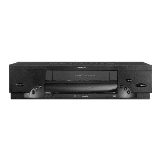
Page 1
VIDEO SERVICE MANUAL 32700 # Service Service Zusätzlich erforderli- GV 26 …, GV 46 … Manual Manual che Unterlagen für den Komplettservice: GV 6000 …, GV 6001 V+ Sicherheit Safety Additionally required Service Manuals for Palermo / GV 6066 Sach-Nr./Part No. Sach-Nr./Part No.
Digital multimeter Stabilized power supply Millivoltmeter Frequenzzähler Millivoltmeter Frequency counter Beachten Sie bitte das Grundig Meßtechnik-Programm, das Sie unter Please note the Grundig Catalog "Test and Measuring Equipment" folgender Adresse erhalten: obtainable from: Grundig electronics GmbH Grundig electronics GmbH Würzburger Str. 150 Würzburger Str.
Bildsuchlauf rückwärts (bei Wiedergabe); Reverse picture search (on playback); Rücklauf bei Stop rewind (on stop) Automatischer Sender Suchlauf Automatic station search Netzanschluß Mains socket & & EURO-AV1-Buchse EURO-AV1-socket EURO-AV2-Buchse (Option) EURO-AV2-socket (Option) Antennenbuchsen Aerial sockets GRUNDIG Service 1 - 5...
Page 6
(on timer programming) Forward picture search (on playback); Bildsuchlauf vorwärts (bei Wiedergabe); fast forward (from stop) Vorlauf (bei Stop) Standbild bei Wiedergabe freeze-frame on playback & & Starts playback function Startet die Wiedergabe 1 - 6 GRUNDIG Service...
Hebel in die Führung (Fig. 4) der Cassetten- with the guide (Fig. 4) of the cassette lid. klappe eintaucht. Fig. 1 Fig. 2 Fig. 3 Fig. 4 GRUNDIG Service 1 - 7...
– Masseverbindung zwischen Chassisplatte und Laufwerk durch Ein- drehen der Masseschraube (Fig. 2) herstellen. – Reestablish the chassis connection between the Family Board and the Drive Mechanism by turning in screw (Fig. 2). 1941 Fig. 6 Fig. 5 Fig. 7 Fig. 8 1 - 8 GRUNDIG Service...
Page 9
5. Meßwerte und Oszillogramme 5. Measured Values and Oscillograms Bei den in den Schaltplänen und Oszillogrammen angegebenen The measured values given in the circuit diagrams and oscillograms Meßwerten handelt es sich um Näherungswerte! are approximates! GRUNDIG Service 1 - 9...
Page 10
(figure following the point). Platinenbezeichnung / Name of PCB Sach-Nummer / Part number PSM1 27599-003.15 52741 KW621 VN05 123456 Fabrikcode / Factory code number Seriennummer / Serial number Produktionsdatum / Production date Produktionscode / Production code 1 - 10 GRUNDIG Service...
Rechts) werden auf dem Display die Betriebszustände mit einer impulse (FTA) wichtig. Diese Impulse erzeugt der Fädeltachogeber Digitalstelle angezeigt. Mit jeder Betätigung der Sensoren ändern (Flügelrad), der mechanisch mit dem Fädelmotor verbunden ist. sich die Werte der Anzeige. GRUNDIG Service 1 - 11...
Page 12
– Testcassette wiedergeben. Nach der Anwahl dieser Ebene ist das Display dunkel und keine Funktion am Gerät möglich. Das Verlassen dieser Ebene und des Servicetestprogrammes ist nur durch das Trennen des Gerätes vom Netz möglich. 1 - 12 GRUNDIG Service...
Page 13
Geräte-Optionscodes und die Abgleichwerte bleiben er- halten. Tausch des EEPROM´s IC7890 Achtung: Nach dem Tausch des EEPROMs, IC7890, muß das Gerät mit den Abgleich-Ebenen 51, 52 (optional) und 53 neu abgeglichen und der Geräte-Optionscode Ebene 40 einge- geben werden. GRUNDIG Service 1 - 13...
For this, the number of the threading tacho pulses (FTA) is important. These signals are generated by the threading tacho generator (butterfly sensor) which is mechanically connected with the threading motor. 1 - 14 GRUNDIG Service...
Page 15
On selection of this level, the display is dark and no function of the VCR Preparation before calling up this level: is active. This level and the service test programme can be terminated – Play the test cassette. only by disconnecting the VCR from the mains. GRUNDIG Service 1 - 15...
Page 16
Replacement of the EEPROM IC7890 Attention: On replacement of the EEPROM, IC7890, the machine must be readjusted according to the Levels 51, 52 (op- tional), and 53, and the VCR option code Level 40 must be entered. 1 - 16 GRUNDIG Service...
IC7020-(3) zu reduzieren. Dieser Punkt wird als Umkehr- in den Trafo übertragen. Die im Trafo gespeicherte Energie baut sich punkt bezeichnet. Die IC-Versorgungsspannung V verhält sich wie nun über die Sekundärwicklungen ab. Durch die Umkehrung der GRUNDIG Service 2 - 1...
Kopfscheibensteuerung. Des weiteren steuert dieser die Aufnahme-/ An IC7400-(24) gibt der µC ein impulsbreitenmoduliertes Rechteck- Wiedergabeumschaltung, sowie die Freigabe der Aufsprechströme. signal (REEL) aus, das sowohl Drehzahl- als auch Phaseninformationen enthält. Dieses wird dem Kopfscheibenmotortreiber IC7300-(13) als Regelspannung zugeführt. 2 - 2 GRUNDIG Service...
Pin 13 und Pin 14 des IC7720 einen Ton-Trap F1740, wo der ohne Umstecken vom Fernsehgerät und vom Videorecorder man den Tonanteil im FBAS-Signal absenkt. Anschließend wird es benutzt werden. verstärkt und über IC7720-(7) sowie der Verstärkerstufe T7725 dem "IN/OUT"-Schaltungsteil (als "VFV"-Signal) zugeführt. GRUNDIG Service 2 - 3...
Page 20
Bei Wiedergabe gelangt das Signal vom Band (FMPV) über den IC7051-(23) und IC7060-(4) an das Kammfilter im IC7060 weitergelei- Kopfverstärker zu einigen Anpaßstufen für Frequenzgang und Lauf- tet. zeit (R3034…T7014). Anschließend führt man es über den Emitterfol- ger T7013 zum Pin 1 des IC7051. 2 - 4 GRUNDIG Service...
Steuersignal "SWIN" den entsprechenden Kopf aus. diesem wird es mit dem Y-Signal addiert. Das Summenprodukt (FMRV) Das Synchronsignal CSYNC läßt die Kopfumschaltung nur am Zeilen- führt man über die Verstärkerstufe T7018 / T7019 dem Kopfverstärker ende zu. GRUNDIG Service 2 - 5...
Hintergrund sowie Einblendungen (Superimpose) in das Wiedergabe- bzw. Durchschleif (EE)-Signal möglich. Dazu beinhaltet der IC7800 einen programmierten Character-ROM mit 128 Zeichen. Der Quarzos- zillator Q1820 für den Hintergrund der Ganzbilddarstellung einschließ- lich der Synchronsignalerzeugung (ohne Zeilensprung) schwingt auf der 4-fachen PAL-Farbträgerfrequenz. 2 - 6 GRUNDIG Service...
This voltage decreases also along with the fact that the polarities of the voltages are reversed by the transformer increasing load. current flows through the secondary windings of the transformer, through the diodes, electrolytic capacitors into the load. GRUNDIG Service 2 - 7...
On IC7400-(24) the µC feeds out a pulse-width-modulated square- wave signal (REEL) containing information on the speed and the phase. This signal is fed to the headwheel motor driver IC7300-(13) and is used as a control voltage. 2 - 8 GRUNDIG Service...
Page 25
"IN/OUT" circuit stage (as a "VFV"-signal) via IC7720-(7) and the taken via the EURO-AV2 socket to the Pay-TV-Decoder. The Decoder amplifier T7725. descrambles the signals and feeds them back to the video recorder. This signal path must be released for the individual programmes when GRUNDIG Service 2 - 9...
Page 26
At pin 23, the comb filter IC7060 feeds produces a defined period pulse corresponding to the loss of level, to out the chroma signal and passes it on via pin 26 to IC7051. In this IC, 2 - 10 GRUNDIG Service...
Page 27
T7105. This transistor works like a diode, turns on and applies approximately 1.3V to IC7110-(23). From this level, the follow- ing detection stage can identify the recording mode and switches all in- circuit switches to record position. GRUNDIG Service 2 - 11...
Each character consists of a 12x18 dot matrix the vertical size of which is determined by the line scanning pattern. The width of the character is determined by the LC 2 - 12 GRUNDIG Service...
Page 29
Servicetestprogramm beenden (siehe Seite 1-11). 3. Automatic Contour Servicetestprogramm aufrufen (siehe Seite 1-11). Hinweise zu der Ebene 52 beachten (siehe Seite 1-12). Control (Option) Ebene 52 aufrufen (siehe Seite 1-11). Servicetestprogramm beenden (siehe Seite 1-11). GRUNDIG Service 3 - 1...
Page 30
1. OSD, C2820 IC7800-(23) mit Masse (Pin 22) verbinden. Frequenz mit C2820 auf 17.734,475kHz 100Hz einstellen. (nur bei bestücktem PAL-Weißtestbild (UHF-Bereich, Kanal 27, Antennenpegel C2820) 67dBµV) einspeisen. EE-Betrieb. Verbindung von IC7800-(23) mit Masse auftrennen. Frequenzzähler: ..........IC7800-(5) 3 - 2 GRUNDIG Service...
Call up the Service Test Programme (see page 1-14). Observe the instrucitons for Level 52 (siehe Seite 1-15). Control (Option) Call up Level 52 (see page 1-14). Terminate the Service Test Programme (see page 1-14). GRUNDIG Service 3 - 3...
Page 32
Connect IC7800-(23) to ground (pin 22). Set the frequency with C2820 to 17,734.475kHz 100Hz. (only with C2820 Feed in a PAL white test pattern (UHF-range, Ch27, 67dBµV fitted) aerial signal). EE mode. Disconnect IC7800-(23) from ground. Frequency counter: ..........IC7800-(5) 3 - 4 GRUNDIG Service...
Page 33
CLKD1 Serieller Bus (Clock) Serial bus (clock) DC DE CREV Capstan "Reverse" Capstan reverse CROT Farbphasenrotation "Ein/Aus" Colour rotation "on/off" Farbsystem Information Colour system information Chroma-Wiedergabesignal "SECAM" Chrominance playback "SECAM" Chroma-Aufnahmesignal "SECAM" Chrominance record "SECAM" GRUNDIG Service 4 - 1...
Longplay video MEH1/2 Hauptlöschkopf Main erase head MESECAM (Mittel Ost Secam) MESECAM (Middle East secam) Monitor Durchschleifsignal Scart1/2 Monitor loop-through scart 1/2 MOT0-3 Kopfmotor Steuerleitungen Head motor Control lines Audio-Stummschaltung Audio mute Nicht verwendet Not connected 4 - 2 GRUNDIG Service...
Wind tacho left WTLD Tachosignal vom linken Wickelteller (Digital) Wind tacho left (Digital) Tachosignal vom rechten Wickelteller Wind tacho right WTRD Tachosignal vom rechten Wickelteller (Digital) Wind tacho right (Digital) GRUNDIG Service 4 - 3 GRUNDIG Service 4 - 4...
Page 36
Platinenabbildungen und Schaltpläne / Layout of PCBs and Circuit Diagrams GV 26 …, GV 46 …, GV 6000 …, GV 6001 V+, GV 6066, GV 6300 … Blockschaltplan / Block Circuit Diagram (Analog) for Megalogic Automatic Contour Control 4 - 5 GRUNDIG Service 4 - 6 GRUNDIG Service...
Page 43
– – 8352 – NOTE ON THE COMPONENTS: 8354 – – "X" components are not used ...Discharge Pos. 2070 before repairing "Y" components are optional Voltages measured in STOP-Mode PSM(30760) GRUNDIG Service 4 - 15 GRUNDIG Service 4 - 16...
Page 48
...V MEASURED IN PLAYBACK MODE VIDOUT L = SEC L L = BG AMLP from DE from IO to DE ...V MEASURED IN RECORD MODE 5ASW from AL from DE 4 - 25 GRUNDIG Service 4 - 26 GRUNDIG Service...
Page 49
SCCONI SCCONI 3535 GNDA GNDA GNDA OCLK/H_2 IPBV IPBV 3534 OCS/OFP -28V ...V MEASURED IN PLAYBACK MODE VIDOUT VIDOUT OCLK ODAT/SACO ...V MEASURED IN RECORD MODE to OS IO(39620) OSCILLOGRAMS GRUNDIG Service 4 - 27 GRUNDIG Service 4 - 28...
Page 50
2.5V for ACC only Basic & ACC 180p 560E 2.5V Standard good 1.5V 2.5V OSCILLOGRAMS for ACC only ...V MEASURED IN PLAYBACK MODE ...V MEASURED IN RECORD MODE VS(39620) 4 - 29 GRUNDIG Service 4 - 30 GRUNDIG Service...
(Pos. 127, Fig. 5) entgegen dem Uhrzeigersinn bewegt and the driving gear alternately until the tape is completely wound up werden, bis das Band komplett in der Cassette aufgewickelt ist. in the cassette. Einfädeln / thread Ausfädeln / unthread Fig. 3 5 - 2 GRUNDIG Service...
– 4 Befestigungsschrauben (Fig. 5) des Cassettenschachtes an – Unscrew the 4 screws (Fig. 5) on the underside of the cassette der Unterseite entfernen. compartment. – Cassettenschacht abheben. – Raise the cassette compartment to remove it. GRUNDIG Service 5 - 3...
Page 63
Klemmscheibe abnehmen (Fig. 10). – Turn the lever by 90° in the direction of the arrow "OPEN" and remove the headwheel together with the lower clamping element (Fig. 10). Klemmscheibe Clamping element Fig. 8 Fig. 9 Fig. 10 GRUNDIG Service 5 - 5...
Page 64
– Aufsprechstrom einstellen (siehe Abgleich Kap. 3). – Check the tape transport (see para 3.1). – Bandlauf kontrollieren (siehe Punkt 3.1). Mylar-Abstandsfolien Mylar distance films Schutzkappe Fig. 11 Protecting cap Klemmscheibe Clamping element Fig. 12 Fig. 13 5 - 6 GRUNDIG Service...
Page 65
– Von unten die vier Sicherungsbolzen (A, Fig. 16) herausdrücken – Push out the four securing bolts (A) from the bottom and remove the und Motorhalter abnehmen. motor holder (Fig. 16). Einbau in umgekehrter Rehenfolge. Reassemble in reverse order. Fig. 15 Fig. 16 GRUNDIG Service 5 - 7...
Page 66
(Pos. 41S) can be released and removed (Fig. 18). Achtung: Kein Fett auf die Capstanwelle bringen. Der Einbau erfolgt Attention: Take care that the capstan does not come into contact with in umgekehrter Reihenfolge. grease. Reassemble in reverse order. Fig. 18 5 - 8 GRUNDIG Service...
Page 67
– Remove the erase head assembly in vertical direction (Fig. 21). Hinweis zum Einbau: Die Löschkopfeinheit muß beim Einbau gera- Note: The erase head assembly must be locked in when refitting it. stet sein. Pos. 9 Pos. 16 Fig. 21 GRUNDIG Service 5 - 9...
– Taste "Standby" drücken. Videokopf Video head Band Tape Ansicht von der Bandoberseite Videospur View to foil side Video track SWIN Spurbild Video Track Diagram TRIV TRIV SYNC SWIN ∆t = -8ms 20ms Fig. 23 Fig. 24 5 - 10 GRUNDIG Service...
Page 69
– Taste "Standby" drücken oder durch Trennen des Gerätes vom – Press the "Standby" button or disconnect the mains. Netz. Bandzug-Einstellstift Tape tension adjustment pin Bremsbandeinstellung Brake Band Adjustment Bandzugeinstellung Tape Tension Adjustment Fig. 26 GRUNDIG Service 5 - 11...
Page 70
Uhrzeigersinn so lange drehen, bis der Wickelteller leicht durchrutscht (Fig. 28). – Wert am Drehmomentmesser muß 7mNm ±3mNm (70gf-cm Pos. 17R Pos. 19R Pos. 18R ±30gf-cm) betragen. Pos. 41S Pos. 45S Fig. 29 Fig. 30 Fig. 31 5 - 12 GRUNDIG Service...
Ersatzteilliste Ersatzteilliste Spare Parts List Spare Parts List 32700 # 32700 # 7 / 96 GV 26 7 / 96 GV 26 VPS SACH-NR. / PART NO.: 77400-765.51 SACH-NR. / PART NO.: 77400-767.51 BESTELL-NR. / ORDER NO.: BESTELL-NR. / ORDER NO.: G.MF 0200 G.MF 0100 POS.
Page 75
Ersatzteilliste Ersatzteilliste Spare Parts List Spare Parts List 32700 # 32700 # 7 / 96 GV 46 7 / 96 GV 46 VPS SACH-NR. / PART NO.: 77400-769.51 SACH-NR. / PART NO.: 77400-770.51 BESTELL-NR. / ORDER NO.: G.MF1500 BESTELL-NR. / ORDER NO.: G.MF 1400 POS.
Page 76
Ersatzteilliste Ersatzteilliste Spare Parts List Spare Parts List 32700 # 32700 # 7 / 96 GV 6000 SV 7 / 96 GV 6000 SV/1 SACH-NR. / PART NO.: SACH-NR. / PART NO.: 77400-716.51 77400-715.51 BESTELL-NR. / ORDER NO.: BESTELL-NR. / ORDER NO.: G.MF 0700 G.MF 0600 POS.
Page 77
Ersatzteilliste Ersatzteilliste Spare Parts List Spare Parts List 32700 # 32700 # 7 / 96 GV 6066 PALERMO 8 / 96 GV 6300 SV GV 6300 SV/1 * SACH-NR. / PART NO.: SACH-NR. / PART NO.: 77400-722.51 77400-776.51 77400-777.51 BESTELL-NR. / ORDER NO.: BESTELL-NR.
Page 78
Ersatzteilliste Ersatzteilliste Spare Parts List Spare Parts List 32700 # 32700 # 6 / 96 LAUFWERK 8 / 96 GV 6001 V+ TAPE DRIVE BESTELL-NR. / ORDER NO.: G.MF 0500 SACH-NR. / PART NO.: 75988-025.50 POS. ABB. SACHNUMMER ANZ. POS. ABB.
Page 79
POS. ABB. SACHNUMMER ANZ. Ersatzteilliste DESCRIPTION BEZEICHNUNG POS. NO. FIG. PART NUMBER QTY. Spare Parts List 0114.000 75988-001.16 KUPPLUNGSHEBEL CLUTCH LEVER 0115.000 75988-001.17 KUPPLUNG CLUTCH 32700 # 0116.000 75988-001.30 WECHSELZAHNRAD CHANGING GEAR 0117.000 75988-001.30 DOPPELRAD DOUBLE GEAR 8 / 96 CHASSISPLATTE MB-DCG161031 0118.000 75988-025.39...
Page 80
POS. SACHNUMMER BEZEICHNUNG POS. SACHNUMMER BEZEICHNUNG ALLE NICHT AUFGEFÜHRTEN E-TEILE SIEHE E-LISTE CHASSISPL. 27599-010.01 POS. PART NUMBER DESCRIPTION POS. PART NUMBER DESCRIPTION 7 / 96 CHASSISPLATTE MB-DCG165011 ALL PARTS NOT LISTED REFER TO FAMILY BOARD MB-DCG165011 T 7402 75988-000.35 SMD-TRANS. DTA 124 EK PARTS-LIST FAMILY BOARD 27599-010.01 L 5802 75988-000.23...
Page 81
Ersatzteilliste Ersatzteilliste Spare Parts List Spare Parts List 32700 # 32700 # ALLE NICHT AUFGEFÜHRTEN E-TEILE SIEHE E-LISTE CHASSISPL. 27599-010.01 7 / 96 7 / 96 CHASSISPLATTE MB-DCDI165051 NETZTEILPLATTE PSM2 ALL PARTS NOT LISTED REFER TO FAMILY BOARD MB-DCDI165051 POWER SUPPLY BOARD PSM2 PARTS-LIST FAMILY BOARD 27599-010.01 SACH-NR.
Page 82
Ersatzteilliste Ersatzteilliste Spare Parts List Spare Parts List 32700 # 32700 # 6 / 96 6 / 96 BEDIENPLATTE PDCG1/2P30 M BEDIENPLATTE PKG11M/12M CONTROL BOARD PDCG1/2P30 M CONTROL BOARD PKG11M/12M SACH-NR. / PART NO.: 27599-002.62 SACH-NR. / PART NO.: 75988-037.18 POS.
Need help?
Do you have a question about the GV 26 Series and is the answer not in the manual?
Questions and answers