Victron energy Venus GX Manual
Hide thumbs
Also See for Venus GX:
- Installation manual ,
- Manual (12 pages) ,
- Preliminary manual (5 pages)
Table of Contents
Advertisement
Quick Links
Venus GX (VGX) manual
1. Introduction
1.1 Description
In many ways the Venus GX (VGX) and the Color Control GX (CCGX) are the same device. They
share a lot of hardware, and they run on identical software - our 'Venus OS' - therefore firmware
numbering is the same; and new version releases always apply to both devices at the same time.
As many of the functions of the two devices are identical, the CCGX Manual should also be consulted
if something is not specifically covered in this VGX manual.
This manual refers to the latest firmware version. A device connected to the internet will perform
new-version updates automatically. Check the latest firmware version here.
Venus GX/CCGX comparison table
See the Victron GX product range page.
1.2 What's in the Box?
Venus GX (VGX)
VE.Can terminator (2 pcs).
Power cable with inline fuse and M8 terminal eyes for battery- or DC busbar-attachment.
Terminal Blocks for all the connectors on each side.
Label showing WiFi key and product details.
Venus GX (VGX) manual
Advertisement
Table of Contents
Troubleshooting

Related Manuals for Victron energy Venus GX


Summary of Contents for Victron energy Venus GX
- Page 1 1. Introduction 1.1 Description In many ways the Venus GX (VGX) and the Color Control GX (CCGX) are the same device. They share a lot of hardware, and they run on identical software - our 'Venus OS' - therefore firmware numbering is the same;...
-
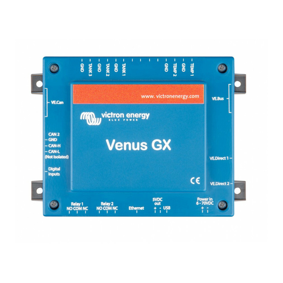
Page 2: Overview Of Connections
1.3 Overview of connections 2. Accessing the device Because the Venus GX has no visual display or buttons, you need either a smartphone, tablet or laptop to access it. This access is called Remote Console. There are three ways to access the Remote Console: Through the online VRM Portal, which requires internet, see chapter 2.1;... - Page 3 Step by step instructions: First, connect the Venus GX to the internet by plugging it into a working Ethernet network which has a DHCP server, as most networks do, and which is connected to the internet. The Venus GX will immediately connect to VRM.
- Page 4 Open VictronConnect, it will start scanning the WiFi network automatically. Once found, select the GX device from the list. Open the Remote Console Notes: If you cannot use VictronConnect, you can use a web browser and navigate to the IP address 172.24.24.1 For added security it is possible to disable the WiFi Access Point.
- Page 5 This video shows how its done: Video 2.3.2 Alternative methods to find the IP Address In case VictronConnect can't be used, here are a few other methods to find the Venus GX, ie. its IP Address. IP Address on VRM On the VRM Portal, you'll find the IP address on the Device List page of the installation.
- Page 6 Network (on Microsoft Windows) In a local network, for example at home, you can also find the Venus GX in the Windows 'Network' overview: Double-clicking the icon will open up Remote Console on LAN. Open the 'Properties' window to see the IP address.
- Page 7 3.1 LEDs Boot-up On the side of the Venus GX, there is a LED. During power-up it it goes through these states: Stage 1: Both green and red illuminate briefly and faintly (it's hard to see the green) for approximately 1 second.
-
Page 8: Digital Inputs
The same button is available on the Octo GX, button is marked SD_BOOT and available under the lid at the top. 4. Digital Inputs The Venus GX has five digital inputs. The channels are accessible via the RJ-12 socket on the side. This is available for self-wiring by the user/installer. 4.1. Wiring details The inputs are non-isolated. - Page 9 Venus GX (VGX) manual RJ12 pinout Input pin1 input1 pin2 input2 pin3 input3 pin4 input4 pin5 pin6 input5 4.2. Configuration Each of the digital inputs can be configured as a pulse meter, or as one of a number of predefined sensors that can also be configured as alarms.
- Page 10 Once the input is configured for its intended purpose, it will show up with other devices. Other parameters related to that function can be configured by entering the device menu and selecting Setup. For pulse meters, you can configure the unit, the multiplier (the volume represented by each pulse) and reset the counter.
-
Page 11: Factory Reset
Venus GX (VGX) manual For other sensors and alarms, you can decide whether the input should be treated as an alarm condition, whether the labels should be inverted, and whether the logical levels should be inverted. To swap the labels attached to the alarm, set Inverted to on. - Page 12 AC-coupled PV with Fronius PV Inverters AC-coupled PV with Fronius PV Inverters This document describes how to setup Energy-storage, Off-grid/Micro-grid and Backup systems with AC-coupled PV, using Fronius PV Inverters. For Fronius information on the same subject, see their MicroGrid flyer. The Victron system monitor, the Color Control GX includes built-in Fronius monitoring.
- Page 13 Fronius / Victron specifics This is a very easy setup. The Fronius Setup Microgrid has been developed in close cooperation with Victron. During commissioning, set the PV Inverter to Setup MG50 (or Setup MG60 for 60 Hz systems). Everything is then pre-configured. The Setup MG settings match the default Victron Assistant settings. Compatible ROW inverters (for “European type AC grid”) are: Fronius Primo (1~, 3 kW up to 8.2 kW) →...
- Page 14 AC-coupled PV with Fronius PV Inverters Ready to start up. Setting up the Victron Multi or Quattro After connecting the MultiPlus or Quattro with the battery, you can now connect a computer through the VE.Bus (in combination with the Victron interface MK2USB) to configure the system with the latest version of the software VE.Configure.
-
Page 15: Remote System Monitoring
Minimum 52.7 62.7 Disconnect 53.0 63.0 More information on adding Assistants is here. Remote system monitoring The Victron system can be monitored through Victron VRM Portal if a Color Control GX is present at the site. The Fronius PV inverter data can be integrated into the Color Control GX and therefore also in the VRM portal. - Page 16 AC-coupled PV with Fronius PV Inverters Q4 Can I use the Fronius Smart Meter? That depends on the type of system and software configuration. A Fronius Smart Meter can be used in these two situations: when used only for reporting to Solarweb when used for limiting export, in a system where the Victron system is not configured as an ESS system.
- Page 17 Option 1: GX device like CCGX or Venus GX When there is a GX device (CCGX, Venus GX, or other) in the system, the best option is to use its Generator Start Stop mechanism. Its the most feature-rich generator start/stop system that we have to offer.
- Page 18 To start such a genset, the open/close contact needs to be converted into a start and stop pulse. Below solution, using standard available timing relays, does exactly that: when the open/close contact closes it generates the start pulse, and when the open/close contact opens again it generates the stop pulse.
- Page 19 Automatic Generator start/stop and k2 relais and relai programmable assistant first to close k1 if voltage under 24v (for exemple) segond to open k1 if ac1 avalable third to close k2 if voltage uper 27v (for exemple) last to open k2 if ac1 not avalable in this case you have a three-wire system with out any think more needed ! i have some systeme using this solution and all looks ok...
- Page 20 Color Control GX manual Color Control GX manual The Color Control GX (CCGX) sits at the heart of your energy installation. All the other system- components - such as inverter/chargers, solar chargers, and batteries - are connected to it. The CCGX ensures that they all work in harmony.
-
Page 21: Installation
All the information in this manual refers to the latest software. Your device will update itself to the latest version automatically. 1. Installation 1.1 Overview of connections 1.2 Snap-on ferrite beads for class B EMI compliance In order to reduce Electromagnetic emissions in compliance with class B EMI you should place the provided snap-on ferrite beads around every connection cable as close as possible to the Color Control. - Page 22 Color Control GX manual around the power leads like this: HQ1654 and earlier For serial numbers HQ1654 and earlier, mount the snap-on ferrite beads as below:...
- Page 23 1.3 Power Power the device using the Power in V+ connector. It accepts 8 to 70 V DC. The device will not power itself from any of the network connections. Be sure to use a 1A slow blow fuse. Powering in systems with VE.Bus BMS When the CCGX is used in an installation with a VE.Bus BMS, connect the Power in V+ on the CCGX to the terminal labelled 'Load disconnect' on the VE.Bus BMS.
- Page 24 Color Control GX manual for any reason (after any operational fault or during a black start). The VE.Bus devices will not boot-up until the CCGX has power …but the CCGX will not boot-up until it has power. This deadlock can be rectified by briefly unplugging the CCGX VE.Bus cable at which point you will observe the VE.Bus products will immediately begin to boot-up.
- Page 25 Only the system connected to the built-in VE.Bus ports is used for the Generator start/stop logic The CCGX will not send proper data to VRM any more. The Venus GX does send information of both systems to VRM: its therefor better to use a Venus GX for systems like this.
- Page 26 USB or via CAN, does not change the maximum. See here for the Venus GX, Octo GX, and other limits. Option 1: Use the VE.Direct to USB interface. The CCGX has two USB ports. Use a USB-hub when more than two USB ports are required.
- Page 27 Other notes: In order to work with the CCGX an MPPT 150/70 needs run firmware v2.00 or newer. You can combine a Skylla-i control panel with a CCGX. You can combine a Ion Control panel with a CCGX. The Skylla-i, Lynx Shunt VE.Can, Lynx Ion + Shunt and the MPPTs with a VE.Can port all power the VE.Can network …so it won't be necessary to power the VE.Can network separately in these circumstances.
-
Page 28: Internet Connectivity
Color Control GX manual For some tank senders it is also possible to configure the capacity and the fluid type from the CCGX - for example the Maretron TLA100. This facility may be available with other senders made by other manufacturers - it's well-worth trying. - Page 29 To monitor this data from your smartphone or tablet download the iOS or Android VRM App. In addition to remote monitoring, an active internet connection allows the CCGX to regularly check for a new firmware versions - which will be automatically downloaded and installed. There are several ways to connect a CCGX to the internet: Run a network cable between a router and the CCGX Ethernet LAN port Connect to a router wirelessly using a USB Wi-Fi dongle plugged into the CCGX...
- Page 30 Using a Wi-Fi dongle it is possible to connect to WEP, WPA and WPA2 secured networks. There are four supported USB Wi-Fi dongles. Two of them are also available from stock at Victron Energy: Partno. BPP900100200 - CCGX WiFi module simple (Nano USB), small, low cost.
- Page 31 …but not on: iPhone 5s with iOS 8.1.1 1.6.5 IP Configuration Almost no installations will need the IP address configuration to be inserted manually as most systems support automatic IP configuration (DHCP) - and that is also the CCGX default setting. If you do need to configure the address manually, select the following template: Complete details of IP requirements, as well as used port numbers will be found in the VRM FAQ -ports and connections used by the CCGX.
- Page 32 Color Control GX manual some mobile companies will report the data used via a website. The amount of data used is also very dependent on the system: More products connected to the CCGX will generate more data. A state change (from inverter to charger for example) will trigger a data transmission, so a system with very frequent state changes will also tend to generate more data.
- Page 33 1.8 Connecting a Fischer Panda Generator See GX - Fischer Panda generators. 1.9 Connecting NMEA-2000 tank senders A thrid party NMEA2000 tank sender must meet the following requirements to be visible on the GX Device: Transmit the NMEA2000 Fluid Level PGN, 127505 The NMEA2000 device class needs to either General (80) in combination with function code Transducer (190), or Sensor (170).
-
Page 34: Operation
Color Control GX manual Optional/additional external sensors are either connected to the solar irradiance sensor with pre-installed plugs or pre-wired to the solar irradiance sensor (external module and ambient temperature only). When external sensors are connected via an appropriate solar irradiance sensor, all measurement data is transmitted to the Victron GX device with the single interface cable. -
Page 35: Installation Notes
The table below describes the colour and function of each wire in the installation. IMT Si-RS485 Series Irradiance Victron RS485 to USB Description Sensor Interface Brown Orange RS485 Data + Orange Yellow RS485 Data - Power Pos - 12 to 28 VDC Black Power Neg/Gnd - 0 VDC Black Thick... - Page 36 Color Control GX manual 2- For detailed wiring/installation notes and specifications refer to the IMT Si-RS485 series solar irradiance sensor 'Quick Reference Guide' and Victron RS485 to USB interface cable ‘Datasheet’. To ensure signal integrity and robust operation, particularly ensure that; Extension cabling complies with the minimum cross-sectional area specifications in the related table - dependent on DC supply voltage and cable length Extension cabling has appropriate shielding and twisted pair cores...
- Page 37 MODBUS Address: 1 Baud Rate: 9600 Data Format: 8N1 (10 Bit) For further support related to configuration of the IMT Si-RS485 Series irradiance sensors please contact IMT Solar directly. 1.10.7 User Interface - GX Device Upon connection to the Victron GX device and power up the IMT Si-RS485 Series irradiance sensor will be automatically detected within a few minutes and appear in the 'Device List' menu.
- Page 38 Color Control GX manual 1.10.8 Data Visualisation - VRM To review logged historical data on the VRM portal, expand the ‘Meteorological Sensor’ widget list and select the ‘Meteorological Sensor’ widget. Data from all available sensor types will be automatically displayed in the graph. Individual sensors/parameters can also be disabled/enabled by clicking on the sensor name/legend.
-
Page 39: Configurable Parameters
2 Configuration 2.1 Configurable parameters After completing the installation and setting up the internet connection (if required), go through the menu from top to bottom to configure the CCGX: Item Default Description General Remote Off Enable this to allow Victron engineers to access your system in case there is a problem. support User and Access level... - Page 40 Color Control GX manual Item Default Description Enabling on VRM will allow connection to the CCGX from anywhere via the VRM portal. Trouble shooting Remote Console Enable on VRM No on VRM Enabling will allow direct connection to the CCGX by typing its IP address or Venus.local into a web browser, or in Enable on LAN No VictronConnect when connected to the same network.
- Page 41 Item Default Description Normally Select the polarity of the relay on the back of the CCGX. 'Normally open' or 'Normally closed'. (Note that setting it to Polarity open normally closed increases the CCGX power draw.) Services This setting enables the ModbusTCP service. ModbusTCP Off...
- Page 42 Color Control GX manual No battery monitor is required: the Multi or Quattro is the only product connected to the battery and has full control over all charge and discharge currents. Therefore it can calculate the correct SOC itself. Configuration: Enable and configure the Battery Monitor in VEConfigure.
- Page 43 In case a battery with built-in monitor is used, such as explained in (C), then that is the dedicated battery Monitor. Refer to section (C). Otherwise, install a BMV or Lynx Shunt VE.Can. Configuration: Configure the battery monitor as per its documentation. In the CCGX, in Settings →...
- Page 44 Color Control GX manual In the image above we have chosen the Automatic setting. When automatic is selected the System setup screen will be as shown in the image below. The 'Automatic' function uses the following logic: When available, it will use a dedicated Battery Monitor, such as the BMV or a Lynx Shunt, or a battery with built-in battery monitor.
- Page 45 situation. As it will not take the discharge and charge currents by those other DC Loads, and also unmonitored chargers, into account. 2.2.5 Details on VE.Bus SOC While the Inverter/Charger is in bulk, the SOC will not rise above the value as set in VEConfigure3 for the “State of charge when Bulk finished“...
- Page 46 Color Control GX manual The limit as set by the user in the CCGX will be applied to all inputs where 'Overruled by remote', configured with VEConfigure, is enabled: Using the example of a boat with two AC inputs and a Quattro where: A Genset capable of delivering 50A is connected to input 1;...
- Page 47 Also the on/off/charger only switch in the CCGX will be disabled in the case. In installation with a VE.Bus BMS, use the rocker switch instead - or add a Digital Multi Control to the installation. Minimum input current limit values When PowerAssist is enabled in VEConfigure, there is a minimum input current limit.
- Page 48 Color Control GX manual 3.2 Phase rotation warning The AC supply, either Generator or Grid, to a three phase inverter/charger system needs to be in the correct rotation, also known as sequence. If not, then the Inverter/chargers will not accept the AC supply and remain in Inverter mode.
- Page 49 And also it will be listed in the Alarm Log on VRM, and an email will be sent; using the VRM Alarm Monitoring system. 3.3 Grid failure monitoring When this feature is enabled, an alarm is raised when the system hasn't been connected to the AC input configured to be Grid or Shore for more than 5 seconds.
-
Page 50: Advanced Menu
Color Control GX manual available, it will report a grid failure. 3.4 Advanced menu Equalisation Starts equalisation. See Multi or Quattro documentation for details. Redetect system Redetects the type of inverter/charger and its features & configuration. Use this feature when, for example, a VE.Bus BMS used to be part of a system, and is no longer. -
Page 51: Introduction And Features
4.1 Introduction and features Enabling DVCC changes a GX device from a passive monitor into an active controller. The available features and effects of enabling DVCC depend on the type of battery used. The effect also depends on the installed Victron components and their configuration. Example 1 - Managed CAN-bus batteries For example, in systems with an Managed CAN-bus BMS battery connected, the GX receives a Charge Voltage Limit (CVL), Charge Current Limit (CCL), Discharge Current Limit (DCL) from that battery and relays that to the connected inverter/chargers... - Page 52 For Gel, AGM, OPzS and other lead batteries, DVCC can be used without any problem. The same is true for Victron Energy lithium batteries with the VE.Bus BMS, the Lynx Ion + Shunt BMS or the Lynx Ion BMS. DVCC is the preferred operating mode for Redflow ZBM2/ZCell batteries using the Redflow CANBus BMS.
- Page 53 firmware' when one of the devices has an incompatible firmware while using DVCC. In case of an ESS System, the ESS Assistant needs to be version 164 or later (Released in November 2017). 4.3 DVCC effects on the charge algorithm Our inverter/chargers and MPPT Solar Chargers use their own internal charge algorithm when in stand-alone mode.
- Page 54 Color Control GX manual Internal The internal charge algorithm (bulk → absorption → float → re-bulk), and the configured charge voltages are active. Inverter/charger indicated charge state: bulk, absorption, float, and-so-forth. MPPT indicated charge state: bulk, absorption, float and-so-forth. (firmware version v1.42 onwards. Earlier versions have a bug that make the MPPT say “Ext.
- Page 55 This setting is available in the “Settings → “System Setup” menu on the GX device. Particulars: 1) In case a CANBUS-BMS is connected and the BMS requests a maximum charge current that is different from the user-configurable setting, the lower of the two will be used. 2) this mechanism only works for Victron inverter/chargers and Solar chargers.
- Page 56 Selectable sources for the battery temperature are: BMV-702 battery monitor BMV-712 battery monitor Lynx Shunt VE.Can battery monitors Temperature inputs on a Venus GX (and same for other GX devices that have a temperature input) Multi/Quattro inverter/charger Solar Chargers (if fitted with a temperature sensor) 4.4.4 Shared Current Sense (SCS)
- Page 57 For such batteries, there is no need to wire allow-to-charge and allow-to-discharge connections to the AUX inputs on a Multi or a Quattro. When inverting, ie in Island mode, Multis and Quattros will shut down when the max discharge current is zero.
- Page 58 Color Control GX manual 5. VRM Portal 5.1 VRM Portal Introduction When connected to the internet, a GX device can be used in combination with the Victron Remote Management (VRM) portal, which enables: Easy remote access to all statistics and systems status online Remote Console on VRM: access and configure your system as if you were standing besides it Remote Firmware updates of connected Solar Chargers and other Victron products.
- Page 59 The transmission of the data logs has been designed to work also on bad internet connections. Lines of up to 70% permenant packet loss are still sufficient to get the data out, even if delayed in some cases. Adding an external storage device When unable to transmit the logs, then the GX device will store them to non-volatile storage (ie.
- Page 60 Color Control GX manual SDXC type microSD cards which have greater than 32 GB capacity are often formatted with exFAT, and therefore cannot be used with the CCGX without reformatting and possibly re- partitioning. Manually transferring datalogs to VRM For devices permanently without Internet, it is possible to take the data out, and then upload it manually from a laptop.
- Page 61 Please be careful with enabling this feature on ESS systems: when grid connection is lost, and the GX device reboots, the system can loose power when rebooting takes too long (when grid is present, the Multi's or Quattro's will enter passthru) 5.4 Trouble shooting data logging This chapter explains what to do when the GX Device cannot transmit data to the VRM Portal.
- Page 62 Color Control GX manual When using Ethernet and State shows 'Unplugged', verify that the Ethernet network cable is not faulty: try another one. The two lights at the back of the CCGX, where the Ethernet RJ45 cable plugs in, should be lit or blinking. Two dead lights indicate a connection problem. WiFi When using Wi-Fi and the menu shows 'No Wi-Fi adapter connected' check the USB connection to the Wi-Fi dongle.
- Page 63 If a Connection error is shown, the CCGX is not able to contact the VRM database. The connection error will show an error code that indicates the nature of the connectivity problem. Also, details of the error message are shown, to facilitate on site IT experts to diagnose the problem. Error #150 Unexpected response text: A connection succeeded, but the result was incorrect.
- Page 64 Color Control GX manual Error #154 DNS Failure: Make sure that a valid DNS server is configured in the Ethernet or WiFi menu. Typically this is assigned automatically by a DHCP server in a network. Error #155 Routing error: VRM is unreachable. This error occurs if an ICMP error is received indicating that no route exists to the VRM server.
- Page 65 Insert the storage device containing the log file(s) In VictronConnect, use the GX Log Converter feature to convert them to Excel sheets. 5.6 Remote Console on VRM - Setup This feature allows full remote control of a GX Device, over the internet: Remote Console on VRM is disabled by default.
- Page 66 Color Control GX manual 5.7 Remote Console on VRM - Trouble shooting Follow these steps to trouble shoot Remote Console on VRM 1. Make sure that Logging to the VRM portal works, see chapter 5.4. Without this; Remote Console on VRM will not work. 2.
-
Page 67: Introduction & Requirements
Last update: 2020-02-12 16:23 ccgx:start https://www.victronenergy.com/live/ccgx:start remote areas. When Remote Console on VRM is enabled, the GX Device will open and maintain a connection to any of the servers pointed to by supporthosts.victronenergy.com. Which currently resolves to two IP addresses (84.22.107.120 and 84.22.108.49), and likely more in the future. The technology used is ssh, and it will try to connect using port 22, 80 and 443, only one of them needs to work. - Page 68 Battery Monitors: BMV-700, BMV-702, BMV-712 and newer, Lynx Shunt VE.Can, Lynx Ion BMS. All Victron MPPT Solar Charge Controllers Required components: Battery system. Victron inverter/charger. Victron Battery monitor. Network cable connection between MFD and a GX device such as a Color Control GX, Venus GX or an Octo GX. UTP network cable.
- Page 69 6.2 Compatible MFDs and instructions Instructions for Garmin MFDs Instructions for Navico MFDs (Simrad, B&D, Lowrance) Instructions for Raymarine Furuno: support on Furuno MFDs is in the pipeline. There is no expected date of availability. 7. Marine MFD integration by NMEA 2000 Since Venus OS v2.40, our GX Devices feature an NMEA 2000-out function.
-
Page 70: Error Codes
Color Control GX manual connected via VE.Direct), and nor is data from solar chargers. 8 Error Codes Different origins of errors On your GX device, some error codes shown will be from the GX device itself, in that case see below list. - Page 71 minimum firmware, and raises Error #48 in case the firmware of one or more connected devices is too old. 9 More information resources CCGX Basic Training Video and Exam CCGX Frequently asked questions CCGX Firmware upgrade to v2.00 or later CCGX Manually updating firmware CCGX Datasheet GX - Generator start/stop...
- Page 72 GX ModbusTCP Manual 1. Introduction ModbusTCP is a feature on our GX devices eg Color Control GX, and also the Venus GX. ModbusTCP is an industry standard protocol, that can be used to interface PLCs or other third party equipment with Victron products. Through the ModbusTCP interface you can read and write date to the chargers, battery monitors, inverter/chargers and other products connected to the GX device.
- Page 73 Additionally this information is also documented on the ‘Unit ID mapping’ tab in the Modbus-TCP excel sheet. For the overall system data, look for com.victronenergy.system in the excel sheet, and use Unit-ID 100. Note that both Unit-ID 0 and Unit-ID 100 map to the same internal address. We recommend to use ID 100, since many ModbusTCP clients and PLCs do not work with ID 0.
-
Page 74: Error Codes And Troubleshooting
IMT solar irradiation sensors 3600 to 3603 (1): These are the auxiliary temperature sensors built-in to our GX devices, such as the Venus GX. For details, see the GX devices datasheet. Battery temperatures as measured by an Inverter/charger, Charger or Solar Charger are available together with the rest of that device's data, not under com.victronenergy.temperature. - Page 75 Besides double checking the mapping, there are two ways to see where the error lies. One is to check the last error as shown in the GX Device menus. And secondly you can look at the error code as is visible on (most but not all) PLCs.
- Page 76 GX ModbusTCP Manual The recommended method for report on ModbusTCP questions is to use the Modifications section on Victron Community. Its frequently visited by many people using ModbusTCP and other methods of integrating with Victron products. Direct company support is only offered on a limited basis. For such support, contact our Victron representative.
- Page 77 Follow these steps: 1. Obtain root access 2. Login with SSH (use for example Putty in Windows - or simply type ssh root@[ip address here] on a Linux or Mac terminal console. 3. List the latest log file: cat /log/dbus-modbustcp/current | tai64nlocal In case of any errors, the output will look like this: 2016-01-08 16:34:24.658248500 INFO 2016-01-08T16:34:24.657 [Server] New...
- Page 78 How to update a GX device How to update a GX device These instructions apply to all GX Devices, such as the Color Control GX (CCGX) and Venus GX (VGX). 1. Changelog The change log is available in Victron Professional.
- Page 79 Step 1. Download Get the latest swu file: Color Control GX: venus-swu.ccgx.swu Venus GX & Octo GX: venus-swu-beaglebone.swu GX Card in the MultiPlus-II or EasySolar GX: venus-swu-nanopi.swu CANvu GX: venus-swu-canvu500.swu Note that the same files, and the change log, is available on Victron Professional. That also features a dropbox connection, so you can always have the latest file available on your laptop.
- Page 80 How to update a GX device Step 4. Initiate the update Navigate to Settings → Firmware → Offline updates. Press Check for updates If the firmware in the microSD-card or USB-stick is newer than the running one, “Update available” item will appear, press it to start the update process.
-
Page 81: Open Source
1. Venus OS: the software on our GX product range and also for the Raspberry Pi Venus OS is the Victron Energy Unix like distro with a linux kernel. Its the software that runs on our of our GX Product range: central and remote monitoring systems. - Page 82 3. Signal K Signal K is a modern and open data format for marine use. Built on standard web technologies including JSON, WebSockets and HTTP, Signal K provides a method for sharing information independently of the underlying communications protocol (e.g. NMEA0183, NMEA2000, SeaTalk, I2C, 1-Wire, ZigBee, etc) in a way that is friendly to WiFi, cellphones, tablets, and the Internet.
- Page 83 Open source Open Source BASIC programs on github want to list your project here? Please go ahead and change this page yourself! 4.2 VE.Direct (MPPT Solar Chargers and BMV Battery Monitors) Arduino: Victron on Arduino - Caravaners Forum VE.Direct reading library for Arduino Other: Use VE.Direct compatible Victron equipment with EMON (Open Energy Monitor) PvMonit : small real-time web interface and export to emonCMS for history (Brick from...
- Page 84 VE.Can tank sender adapter (no updates available) Color Control GX (update via internet or with an sdcard) Venus GX (update via internet or with an sdcard) Notes: Remotely updating firmware in VE.Bus products (Inverters, Multis and Quattros) is not possible and will also not become possible.
- Page 85 2. Updating a VE.Can product via USB 2.1 VE.Can USB update: Instructions 1. Download and install VE Power Setup from our Software downloads page. 2. Obtain the necessary firmware file on the Victron Professional portal. 3. Connect the VE.Can product to the computer, using the CAN-USB Adapter. 4.
- Page 86 Remotely changing Assistant configuration is possible. VE.Bus firmware versions 416 and 417 can not be configured remotely Remote configuring firmware version 418 or later requires the CCGX or Venus GX to run v2.10 or later The firmware version of the VE.Bus system must stay the same, in between downloading, changing and uploading settings.
- Page 87 Choose “Get settings”. Save the settings file with an appropriate name. Choose “Open location of saved settings”. Double click on the settings file. Depending on the system configuration “VE.Bus System Configurator” or “VEConfig” will open. Make the required changes. Close the configuration tool. The settings file will automatically be saved. Go back to VE Power Setup, and choose “Send Settings”.
- Page 88 So even though the unit restarts, the writing process should not be effected. It important that the router starts itself when the AC power returns of course. And it is important that the CCGX (or Venus GX) is powered from DC: it should not lose power during this process.
- Page 89 Two-way communication status encircled in red: 5.2 Two way communication: Troubleshooting As a first step, carefully go through above steps of configuring Two-way communication. Error "VRM API not responding" This error indicates a network or firewall issue between the computer running VE Power Setup and the backend.
-
Page 90: Windows Xp
VE Power Setup manual Error "Problem communicating with two-way communication relay server" This indicates a problem between your current location and the two-way communication relay server. The relay server, https://pubsub.pubnub.com/, is used to connect to the Color Control, despite it being behind a firewall. -
Page 91: Available Accessories
Cerbo GX - Our newly released GX product. Color Control GX - Our first released GX product, the CCGX has a display and buttons. Venus GX - The Venus GX has more analog and digital IO, no LCD and is more cost effective than the CCGX. - Page 92 MultiPlus-II GX and User interface Cerbo GX CCGX Venus GX Octo GX CANvu GX Maxi GX EasySolar-II Appearance GX Touch 50 LCD Display & 4.3“ touch- optional touch Display no display no display 2×16 character display 7 buttons screen (16)
- Page 93 Victron GX product range MultiPlus-II GX and User interface Cerbo GX CCGX Venus GX Octo GX CANvu GX Maxi GX EasySolar-II MultiPlus-II Third party GX and Cerbo GX CCGX Venus GX Octo GX CANvu GX Maxi GX compatibility EasySolar-II Canbus-BMS Many battery brands.
- Page 94 GUI and/or ModbusTCP. 8. In the Venus GX hardware there are two relays - at present only one of them is available for use. 9. The tank level inputs are resistive and should be connected to a resistive tank sender. Victron does not supply tank senders.
- Page 95 The Bluetooth feature of the Cerbo GX allows to configure its WiFi and Ethernet settings from within VictronConnect. The secondary CAN port, available on some GX devices as per table above, can be configured to be used as a BMS-Can port, as well as other profiles. For details, see manual. DIN rail mounting requires additional accessory - DIN35 Adapter.
- Page 96 VRM: Remote firmware update 1. Introduction This manual describes how to remotely update firmware. This functionality requires the device to be updated connected to a GX device (CCGX, Venus GX, or other). Features: 1. Remotely update internet-connected products straight from the VRM Portal 2.
-
Page 97: How Does It Work
MPPT Solar Charge Controllers (1) BMV Battery Monitors Phoenix Inverters Products connected via VE.Can communication port: MPPT Solar Charge Controllers Skylla-i battery chargers 2.3 How does it work? 1. The new firmware file is first uploaded to the system. 2. Once received and verified, the GX device starts updating the firmware of the connected device. - Page 98 VRM: Remote firmware update BMVs Updating firmware on a BMV that is connected via a canbus interface is not possible. VE.Bus Products (Multis, Quattros, high power Inverters) Remotely updating firmware in VE.Bus products (Inverters, Multis and Quattros) is not possible and will also not become possible.
- Page 99 There, any device for which a new firmware version is available will show a green Update button. Press that button to initiate the update. Step 2. Update process Step 3. Finished...
-
Page 100: Uploading A Firmware File
VRM: Remote firmware update 4. Uploading a firmware file In most situations the system will already have a firmware file available; no need to upload anything yourself. Sometimes however it is necessary to upload a file from your computer; and this chapter explains how that's done. -
Page 101: Troubleshooting
VRM: Remote firmware update Advanced VRM Widgets VRM: Remote VEConfigure VRM World Two-step verification VRM Portal change log VRM JSON API v2 Linking to a dealer in VRM Looking for dependable RV batteries? Rely on Victron Energy for quality and long-lasting products.
Need help?
Do you have a question about the Venus GX and is the answer not in the manual?
Questions and answers