Table of Contents
Advertisement
Quick Links
A l l t e s t I n s t r u me n t s , I n c .
5 0 0 C e n t r a l A v e .
F a r mi n g d a l e , N J 0 7 7 2 7
P : ( 7 3 2 ) 9 1 9 - 3 3 3 9
F : ( 7 3 2 ) 9 1 9 - 3 3 3 2
a l l t e s t . n e t
s s a l e s @ a l l t e s t . n e t
T h e t e s t & me a s u r e me n t
e q u i p me n t y o u n e e d a t
t h e p r i c e y o u w a n t .
A l l t e s t c a r r i e s t h e w o r l d ' s l a r g e s t s e l e c t i o n o f
u s e d / r e f u r b i s h e d b e n c h t o p t e s t & me a s u r e me n t
e q u i p me n t a t 5 0 % t h e p r i c e o f n e w .
O O u r e q u i p me n t i s g u a r a n t e e d w o r k i n g , w a r r a n t i e d , a n d
a v a i l a b l e w i t h c e r t i f i e d c a l i b r a t i o n f r o m o u r i n - h o u s e s t a f f
o f t e c h n i c i a n s a n d e n g i n e e r s .
• 1 0 + f u l l t i me t e c h n i c i a n s w i t h o v e r 1 5 0 y e a r s o f
s p e c i a l i z a t i o n
• 9 0 d a y w a r r a n t y & 5 d a y r i g h t o f r e t u r n o n a l l
e q u i p me n t
• • 1 - 3 y e a r w a r r a n t i e s f o r n e w a n d
p r e mi u m- r e f u r b i s h e d e q u i p me n t
• E v e r y u n i t t e s t e d t o O E M s p e c i f i c a t i o n s
• S a t i s f a c t i o n g u a r a n t e e d
Y o u h a v e p l a n s , w e w i l l h e l p y o u a c h i e v e t h e m.
A n y p r o j e c t . A n y b u d g e t .
t
G e t a q u o t e t o d a y !
C C a l l ( 7 3 2 ) 9 1 9 - 3 3 3 9 o r e ma i l s a l e s @a l l t e s t . n e t .
Advertisement
Chapters
Table of Contents

Related Manuals for HP E1419A


Summary of Contents for HP E1419A
- Page 1 T h e t e s t & me a s u r e me n t e q u i p me n t y o u n e e d a t t h e p r i c e y o u w a n t . A l l t e s t I n s t r u me n t s , I n c .
-
Page 2: Table Of Contents
About this Chapter ........13 Configuring the HP E1419A ....... 13 Setting the Logical Address Switch . - Page 3 Reading Status Groups Directly ......95 HP E1419A Background Operation ......96 Updating the Status System and VXIbus Interrupts .
- Page 4 How Your Algorithms Fit In ......112 Accessing the E1419A’s Resources ......113 Accessing I/O Channels .
- Page 5 Firmware-Update Download ....... 175 Chapter 6. HP E1419 Command Reference ......177 Using This Chapter .
- Page 6 CALibration:SETup? ........214 CALibration:STORe ........215 CALibration:TARE .
- Page 7 OUTPut:CURRent:AMPLitude ......249 OUTPut:CURRent:AMPLitude? ......250 OUTPut:CURRent[:STATe] .
- Page 8 [SENSe:]STRain:GFACtor ......285 [SENSe:]STRain:GFACtor? ......286 [SENSe:]STRain:POISson .
- Page 9 Noise Due to Inadequate Card Grounding ......377 HP E1419 Noise Rejection ....... . 378 Normal Mode Noise (Enm) .
-
Page 10: Warranty
For warranty service or repair, this product must be returned to a service facility designated by Hewlett-Packard (HP). Buyer shall pre- pay shipping charges to HP and HP shall pay shipping charges to return the product to Buyer. However, Buyer shall pay all shipping charges, duties, and taxes for products returned to HP from another country. -
Page 11: Safety Symbols
Documentation History All Editions and Updates of this manual and their creation date are listed below. The first Edition of the manual is Edition 1. The Edi- tion number increments by 1 whenever the manual is revised. Updates, which are issued between Editions, contain replacement pages to correct or add additional information to the current Edition of the manual. -
Page 12: Declaration Of Conformity
Supplementary Information: The product herewith complies with the requirements of the Low Voltage Directive 73/23/EEC and the EMC Directive 89/336/EEC (inclusive 93/68/EEC) and carries the "CE" mark accordingly. Tested in a typical configuration in an HP C-Size VXI mainframe. March, 1997... - Page 13 Notes...
-
Page 14: Chapter 1. Getting Started
• Configuring the HP E1419A ......13 • Instrument Drivers ....... . 21 •... -
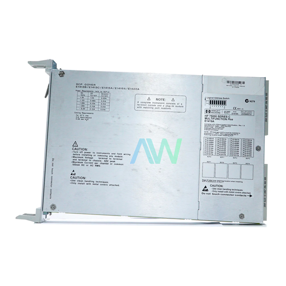
Page 15: Setting The Logical Address Switch
Setting the Logical Follow the next figure and ignore any switch numbering printed on the Logical Address switch. When installing more than one HP E1419A in a Address Switch single VXIbus Mainframe, set each instrument to a different Logical Address. -
Page 16: Installing Signal Conditioning Plug-Ons
SCP positions 4 through 7. CAUTION Use approved Static Discharge Safe handling procedures anytime you have the covers removed from the HP E1419A or are handling SCPs. 1 Installing SCPs: Removing the Cover E1419A Chapter 1 Getting Started 15... - Page 17 The only SCPs supported in SCP positions 0 through 3 are: HP E1501 HP E1513 HP E1502 HP E1514 HP E1508 HP E1515 HP E1509 HP E1516 HP E1512 HP E1517 2 Installing SCPs E1419A 16 Getting Started Chapter 1...
- Page 18 3 Installing SCPs: Reinstalling the Cover E1419A Chapter 1 Getting Started 17...
- Page 19 4 Installing SCPs: Labeling E1419A 18 Getting Started Chapter 1...
-
Page 20: Disabling The Input Protect Feature (Optional)
Disabling the Input Disabling the Input Protect feature voids the HP E1419A’s warranty. The Input Protect feature allows the HP E1419A to open all channel input relays Protect Feature if any input’s voltage exceeds ±19 volts (±6 volts for non-isolated digital (optional) I/O SCPs). - Page 21 Accessing and Locating JM2201 and JM2202 E1419A 20 Getting Started Chapter 1...
-
Page 22: Instrument Drivers
Examples on CD All example programs mentioned by file name in this manual are available on the "Driver CD ROM" supplied with your HP E1419A. See the HP VEE Program Examples Chapter, page 147 for specific location of files on the... - Page 23 22 Getting Started Chapter 1...
-
Page 24: Chapter 2. Field Wiring
Manuals" section. Chapter contents include: • Planning Wiring Layout for the HP E1419 ....23 • Faceplate Connector Pin-Signal List ....27 •... -
Page 25: Scp Types And Signal Paths
Figure 2-1 Channel Numbers at SCP Positions SCP Types and Different SCP types (analog sense, analog source, digital I/O) use different signal paths in the HP E1419A. We’ll discuss each of these basic types. Signal Paths Analog Sense SCPs Analog sense SCPs connect signals at the faceplate connector and pass these signals (most with signal amplification and/or filtering) to the analog multiplexer and thus to the A/D for measurement. -
Page 26: Pairing Sense And Source Scps For Resistance Measurements
With digital SCPs, the signal path to and from the face plate connectors and the SCP is as always, the Hi and Lo signal paths. The HP E1534, HP E1536, and HP E1538 digital SCPs provide one digial bit per Hi and Lo pair while... -
Page 27: Planning For Thermocouple Measurements
Figure 2-2 Pairing Source and Sense SCP Channels Planning for You can wire your thermocouples and your thermocouple reference temperature sensor to any of the HP E1419’s channels. When you execute Thermocouple your scan list, you only have to make sure that the reference temperature... -
Page 28: Faceplate Connector Pin-Signal Lists
Faceplate Connector Pin-Signal Lists Figure 2-3 shows the Faceplate Connector Pin Signal List for the HP E1419A. Figure 2-3 HP E1419A Faceplate Connector Pin Signals Chapter 2 Field Wiring 27... -
Page 29: Optional Terminal Modules
The HP E1419A Option A3F Terminal Module is available to interface the HP E1419A to an HP E1586A rack mount terminal panel (see Page 44). The SCPs and The same Terminal is used for all field wiring regardless of which Signal Conditioning Plug-on (SCP) is used. -
Page 30: Option 11 Terminal Module Layout
Option 11 Terminal Figure 2-4 shows the Option 11 Screw Terminal Module feature and connector locations. Module Layout Figure 2-4 The Option 11 Screw Terminal Module Chapter 2 Field Wiring 29... -
Page 31: Option 12 Terminal Module Layout
Option 12 Terminal Figure 2-5 shows the Option 12 Spring Terminal Module features and connector locations. Module Layout Figure 2-5 The Option 12 Spring Terminal Module 30 Field Wiring Chapter 2... -
Page 32: Reference Temperature Sensing With The Hp E1419A
The Terminal Modules provide an on-board thermistor for sensing isothermal reference temperature of the terminal blocks. Also provided is a jumper set (JM1 in Figures 2-5 and 2-4) to route the HP E1419A’s on-board current source to a thermistor or RTD on a remote isothermal reference block. -
Page 33: Configuring The On-Board/Remote Reference Jumpers
Option 11 Terminal Module. The Thermistor is used for reference junction temperature sensing for thermocouple measurements. See figure on page 37 to remove the cover Figure 2-8 Temperature Sensing for HP E1419 Terminal Module 32 Field Wiring Chapter 2... - Page 34 Terminal Module. 6. HP recommends that the cooling fan switch on the back of the of an HP E1401 Mainframe is in the "High" position. The normal variable...
-
Page 35: Preferred Measurement Connections
For any A/D Module to scan channels at high speeds, it must use a very short sample period (<10µsecond for the HP E1419). If significant normal mode noise is presented to its inputs, that noise will be part of the measurement. -
Page 36: Preferred Measurement Connections
Figure 2-9 Preferred Signal Connections Chapter 2 Field Wiring 35... - Page 37 Figure 2-10 GRD/GND Circuitry Opt. 12 Terminal Module Figure 2-11 Grounding Option 12 Guard Terminals 36 Field Wiring Chapter 2...
- Page 38 Figure 2-12 Wiring and Connecting the E1419 Terminal Module Chapter 2 Field Wiring 37...
- Page 39 Figure 2-13 Wiring and Connecting the E1419 Terminal Module (Cont.) 38 Field Wiring Chapter 2...
- Page 40 Figure 2-14 Attaching the HP E1419 Terminal Module Chapter 2 Field Wiring 39...
- Page 41 Figure 2-15 Removing the HP E1419 Terminal Module 40 Field Wiring Chapter 2...
-
Page 42: Wiring And Attaching The Terminal Module
Wiring and Attaching the Terminal Module Figures 2-12 and 2-13 show how to open, wire, and attach the terminal module to an HP E1419. Figure 2-16 Additional Component Location Information Figure 2-17 Series & Parallel Component Examples Chapter 2 Field Wiring 41... -
Page 43: Option 11 Terminal Module Wiring Map
Figure 2-18 HP E1419A Option 11 Terminal Module Map 42 Field Wiring Chapter 2... -
Page 44: Attaching/Removing The Hp E1419 Terminal Module
Attaching/Removing the HP E1419 Terminal Module Figure 2-14 shows how to attach the terminal module to the HP E1419 and Figure 2-19 HP E1419A Option 12 Terminal Module Map Figure 2-15 shows how to remove it. Chapter 2 Field Wiring 43... -
Page 45: Adding Components To The Option 12 Terminal Module
Adding Components to the Option 12 Terminal Module The back of the terminal module P.C. board provides surface mount pads which you can use to add serial and parallel components to any channel’s Figure 2-20 Option A3F signal path. Figure 2-16 shows additional component locator information (see the schematic and pad layout information on the back of the teminal module P.C. -
Page 46: Option 11 Terminal Module Wiring Map
Figure 2-19 shows the Terminal Module map for the HP E1419. The Option A3F Option A3F allows an HP E1419 to be connected to an HP E1586 Rack Mount Terminal Panel. The option provides 4 SCSI plugs on a Terminal Module to make connections to the Rack Mount Terminal Panel using 4 separately ordered SCSI cables. - Page 47 46 Field Wiring Chapter 2...
-
Page 48: Chapter 3. Programming The Hp E1419A Multifunction Plus
Using the Status System ......90 • HP E1419A Background Operation ....96 •... -
Page 49: Overview Of The Hp E1419 Multifunction Plus
Plus Multifunction The HP E1419 is a complete data acqusition and control system on a single VXI card. It is multifunction because it uses the Signal Conditioning Plug-on(SCP) concept whereby you can mix and match your analog... - Page 50 ’C’ functions). Declared global variables can be shared by any algorithm. HP VEE can read or write any local or global variable in any algorithm by using SCPI syntax that actually identifies the variable by name, but a more efficient means of reading data is available through the E1419’s FIFO and...
- Page 51 Figure 3-2 HP E1419A Cycle Phases FIFO/CVT to characterize what’s happening inside the E1419 and to provide an operator view of any input/output channel, variable, or constant. Output SCP’s derive their channel values from O-variables that are written by the algorithms. O100-O163 are read/write global variables that are read after all algorithms have finished executing.
- Page 52 And, programming the card has been made very easy to understand. HP chose C as the language used to write user programs since that language is already considered the industry standard. Choosing C allows you to write algorithms on PC’s or UNIX workstations that have C...
-
Page 53: Operating Model
The HP E1419’s design allows the user to specify when output signals begin relative to the start of the trigger cycle. Outputs then always occur at the same time, every time. The programming task is further made easy with this design because all the difficult structure of handling input and output channels is done automatically. -
Page 54: Executing The Programming Model
Executing The Programming Model This section shows the sequence of programming steps that should be used for the HP E1419. Within each step, most of the available choices are shown using example command sequences. Further details about various SCPI commands can be found in the Command Reference Chapter 6. A "command sequence"... - Page 55 *RST. Figure 3-5 shows a block diagram of the HP E1419A with the numbered programming steps and various SCPI commands associated with those steps.
- Page 56 Figure 3-4 Programming Sequence Chapter 3 Programming the HP E1419A 55...
-
Page 57: Programming Overview Diagram
Figure 3-5 Programming Model Block Diagram 56 Programming the HP E1419A Chapter 3... -
Page 58: Setting Up Analog Input And Output Channels
Programmable Current Source SCP, the HP E1518 Resistance Measurement SCP, the HP Analog SCP E1510 Sample and Hold SCP, and the HP E1511 Transient Strain SCP. See Parameters the particular SCP’s User’s manual to determine the gain, filter cutoff frequency, or excitation amplitude selections that it may provide. -
Page 59: Setting Filter Cutoff Frequency
The Current Source SCP supplies excitation current for resistance type and HP E1518 Current measurements. These include resistance, and temperature measurements using resistance temperature sensors. The commands to control the Source SCPs HP E1505 Current Source and HP E1518 Resistance Measurement SCPs are: OUTPut:CURRent:AMPLitude <amplitude>,(@<ch_list>) and OUTPut:CURRent[:STATe] <enable>. •... -
Page 60: Linking Channels To Eu Conversion
HP E1532. 2. The HP E1518 Current Measurement SCP is a combinaation of 4 channels of current source (same as the HP E1505), and 4 channels of amplified analog input (same as the HP E1508). The current source channels are on the lower four channels of the HP E1518. - Page 61 However, it is up to you to choose range values that will provide good measurement performance (avoiding over-ranges and select ranges that provide good resolution based on the input signal). In general, measurements can be made at full speed using auto-range. 60 Programming the HP E1419A Chapter 3...
- Page 62 The excite_current parameter is used only to tell the EU conversion what the Current Source SCP channel is now set to. Excite_current is specified in Amps DC and the choices for the HP E1505 SCP are 30e-6 (or MIN) and 488e-6 (or MAX). Select 488µA for measuring resistances of less than 8,000 Ohms.
- Page 63 1. Resistance temperature measurements (RTDs and THERmistors) require the use of Current Source Signal Conditioning Plug-Ons. The following table shows the Current Source setting that must be used for the following RTDs and Thermistors: 62 Programming the HP E1419A Chapter 3...
- Page 64 7 to temperature EU conversion for 100Ω RTDs with .00385 TC. Thermocouple Measurements Thermocouple measurements are voltage measurements that the EU conversion changes into temperature values based on the sub_type parameter and latest reference temperature value. Chapter 3 Programming the HP E1419A 63...
- Page 65 The sub_type parameter must specify: For RTDs; "85" or "92" (for 100 Ohm RTDs with 0.00385 or – 0.00392 Ohms/Ohm/Degree C temperature coefficients respectively) For Thermistors; only "5000" (See previous note on page 3-63) – 64 Programming the HP E1419A Chapter 3...
- Page 66 <ref_chan> channel in the scan list before the related thermocouple measuring channels. Now when analog channels are scanned, the HP E1419A will include the reference channel in the scan list and will scan it before the specified thermocouples are scanned. The reference measurement will be stored in the Reference Temperature Register.
- Page 67 <bridge_type> is not a parameter but is part of the command syntax. The following table relates the command syntax to bridge type. See the HP E1506 and HP E1507, and HP E1511 SCPs’ user’s manual for bridge schematics and field wiring information.
-
Page 68: Linking Output Channels To Functions
• The <ch_list> parameter specifies the channels to configure. The HP E1533 has 2 channels of 8 bits each. All 8 bits in a channel take on the configuration specified for the channel. The HP E1534 has 8 I/O bits that are individually configured as channels. -
Page 69: Setting Up Digital Outputs
To set the lower 8 bit channel of an HP E1533 in SCP position 4 to input SENS:FUNC:COND (@132) To set the upper 4 channels (bits) of an HP E1534 in SCP pos 5 to input states SENS:FUNC:COND (@144:147) Frequency Function The frequency function uses two commands. - Page 70 • The <ch_list> parameter specifies the channels to configure. The HP E1533 has 2 channels of 8 bits each. All 8 bits in a channel take on the configuration specified for the channel. The HP E1534 has 8 I/O bits that are individually configured as channels.
- Page 71 To set the upper 8 bit channel of an HP E1533 in SCP position 7 to output SOUR:FUNC:COND (@157) To set the lower 4 channels (bits) of an HP E1534 in SCP pos 6 to output states SOUR:FUNC:COND (@156:159) Variable Width Pulse Per Trigger This function sets up one or more HP E1534 channels to output a single pulse per trigger (per algorithm execution).
- Page 72 O150 = 0.1e-3; Fixed Width Pulses at Variable Frequency (FM) This function sets up one or more HP E1534 channels to output a train of pulses. A companion command sets the width (↑ edge to ↓ edge) of the pulses. The frequency of the pulse train from these channels is controlled by Algorithm Language statements.
-
Page 73: Performing Channel Calibration (Important!)
SCPs to different SCP locations. How to Use *CAL? When you turn power on to the HP E1419A after you have first installed your SCPs (or after you have moved SCPs), the module will use approximate values for calibration constants. This means that input and output channels will function although the values will not be very accurate relative to the HP E1419A’s specified capability. - Page 74 When you change the channel gain and/or filter cut-off frequency on programmable SCPs (using INPut:GAIN, or INPut:FILTer ... ) • When you change output current amplitude on the HP E1505 or HP E1518 SCPs. • When you re-configure SCPs to different locations. This is true even if you replace an SCP with an identical model SCP because the calibration constants are specific to each SCP channel’s individual...
-
Page 75: Defining C Language Algorithms
ALG:DEF ’globals’,’static float output_max = 1, coefficients[ 10 ];’ If the global definition exceeds 256 characters, you need to download an indefinite block header, the definitions, and terminated by a LF/EOI sequence: 74 Programming the HP E1419A Chapter 3... -
Page 76: Algorithm Definition
Chapter 4). Algorithms are removed from memory only by issueing a *RST or power-ON condition. HP VEE text boxes are the best tool for storing the algorithm code and will be used extensively by this manual. See the "temp1419.vee" example program in Chapter 5 illustrates downloading algorithms to the HP E1419A. -
Page 77: Defining Data Storage
See FORMat command in Chapter 5 for details. REAL,32 means real 32-bit (no conversion, fastest) REAL same as above REAL,64 means real 64-bit (values converted) ASCii,7 means 7-bit ASCII (values converted) ASCii same as above (the *RST condition) 76 Programming the HP E1419A Chapter 3... -
Page 78: Selecting The Fifo Mode
E1419 keep from generating the IEEE-754 numbers. Selecting the The HP E1419A’s FIFO can operate in two modes. One mode is for reading FIFO values while algorithms are executing, the other mode is for reading FIFO Mode FIFO values after algorithms have been halted (ABORT sent). -
Page 79: Setting Up The Trigger System
Setting up the Trigger System Arm and Trigger Figure 3-7 shows the trigger and arm model for the HP E1419A. Note that when the Trigger Source selected is TIMer(the default), the remaining Sources sources become Arm Sources. Using ARM:SOUR allows you to specify an event that must occur in order to start the Trigger Timer. - Page 80 TRIGger[:IMMediate] IMMediate The trigger signal is always true (scan starts when an INITiate:… command is received). SCP Trigger Bus (future HP or SCP Breadboard) TIMer The internal trigger interval timer (must set Arm source) TTLTrg<n> The VXIbus TTLTRG lines (n=0 through 7) NOTES 1.
-
Page 81: Programming The Trigger Timer
After you have defined all of your algorithms, you send the ALG:TIME? command with its <alg_name> parameter set to ’MAIN’. This causes the HP E1419A’s driver to analyze the time required for all four phases of the execution cycle; Input, Update, Execute Algorithm, and Output. The value returned from ALG:TIME? ’MAIN’... -
Page 82: Outputting Trigger Signals
Outputting Trigger The HP E1419A can output trigger signals on any of the VXIbus TTLTRG lines. Use the OUTPut:TTLTrg<n>[:STATe] ON | OFF command to select Signals one of the TTLTRG lines and then choose the source that will drive the TTLTRG line with the command OUTPut:TTLTrg:SOURce command. -
Page 83: The Operating Sequence
... and the algorithms start to execute. Figure 3-8 Sequence of Loop Operations The Operating The HP E1419A has four major operating phases. Figure 3-8 shows these phases. A trigger event starts the sequence: Sequence 1. (INPUT); the state of all digital inputs are captured and each analog input channel that is linked to an algorithm variable is scanned. -
Page 84: Retrieving Algorithm Data
However, all algorithms have access to the remaining 502 elements. Data is retrieved from the CVT with: DATA:CVT? (@10,12,14:67) The format of data comming from the CVT is determined by the FORMat command. Chapter 3 Programming the HP E1419A 83... - Page 85 The FIFO’s most valuable service is to keep your computer from having to spend too much time acquiring data from the E1419. This is ideal for HP VEE which has many other operator interactions and analysis to perform. HP VEE can quickly read the buffered data when required.
- Page 86 FIFO after "measuring" false SENS:DATA:FIFO:COUNT? query for values still in FIFO input n_values here if n_values if any values... SENS:DATA:FIFO:PART? n_values input read_data here get remaining values from FIFO end if Chapter 3 Programming the HP E1419A 85...
-
Page 87: Modifying Running Algorithm Variables
20 updates A way to synchronize variable updates with an external event is to send the ALGorithm:UPDate:CHANnel ’<dig_chan/bit>’ command. • The <dig_chan/bit> parameter specifies the digital channel/bit that controls execution of the update operation. 86 Programming the HP E1419A Chapter 3... -
Page 88: Enabling And Disabling Algorithms
To enable ALG1 and ALG2, and disable ALG3 and ALG4: ALG:STATE ’ALG1’,ON enable algorithm ALG1 ALG:STATE ’ALG2’,ON enable algorithm ALG2 ALG:STATE ’ALG3’,OFF disable algorithm ALG3 ALG:STATE ’ALG4’,OFF disable algorithm ALG4 ALG:UPDATE changes take effect at next update phase Chapter 3 Programming the HP E1419A 87... -
Page 89: Setting Algorithm Execution Frequency
ARM:SOURCE IMMEDIATE (*RST default) TRIGGER:COUNT INF (*RST default) TRIGGER:TIMER .010 (*RST default) TRIGGER:SOURCE TIMER (*RST default) specify data format FORMAT ASC,7 (*RST default) select FIFO mode SENSE:DATA:FIFO:MODE BLOCK may read FIFO while running 88 Programming the HP E1419A Chapter 3... - Page 90 / div, 13 ); writecvt( b * mult, 14 ); writecvt( c - sub, 15 );’ Pre-set coefficients ALG:SCAL ’ALG1’,’div’,5 ALG:SCAL ’ALG1’,’mult’,5 ALG:SCAL ’ALG1’,’sub’,0 ALG:UPDATE initiate trigger system (start algorithm) INITIATE retrieve data SENSE:DATA:CVT? (@10:15) Chapter 3 Programming the HP E1419A 89...
-
Page 91: Using The Status System
Using the Status System The HP E1419A’s Status System allows you to quickly poll a single register (the Status Byte) to see if any internal condition needs attention. Figure 3-11 shows that the three Status Groups (Operation Status, Questionable Data, and the Standard Event Groups) and the Output Queue all send summary information to the Status Byte. - Page 92 Figure 3-12 HP E1419 Status System Chapter 3 Programming the HP E1419A 91...
- Page 93 Operation Complete *OPC command executed and instrument has completed all pending operations. Request Control Not used by HP E1419A Query Error Attempting to read empty output queue or output data lost. Device Dependent A device dependent error occurred. See Appendix B.
-
Page 94: Enabling Events To Be Reported In The Status Byte
Status Byte. Questionable Data Group Examples If you only wanted the "FIFO Overflowed" condition to be reported by the QUE bit (bit 3) of the Status Byte, you would execute; Chapter 3 Programming the HP E1419A 93... -
Page 95: Reading The Status Byte
If bit 8, 9 or 10 is set, error messages will be found in the Error Queue. If bit 7 is set, error messages will be in the error queue following the next *RST or cycling of power. Use the SYST:ERR? command to read the error(s). 94 Programming the HP E1419A Chapter 3... -
Page 96: Clearing The Enable Registers
Status Byte and check the RQS bit to determine if there are any status conditions which need attention. In this way the RQS bit is like the HP-IB’s SRQ (Service Request) line. The difference is that while executing an HP-IB serial poll (SPOLL) releases the SRQ line, executing the *STB? command does not clear the RQS bit in the Status Byte. -
Page 97: Hp E1419A Background Operation
The driver is required to set up the type of measurement to be run, modify algorithm variables, and to unload data from the card after it appears in the CVT or FIFO. Once the INIT[:IMM] command is given, the HP E1419A is initiated and all functions of the trigger system and algorithm execution are controlled by its on-board control processor. -
Page 98: Updating The Status System And Vxibus Interrupts
Updating the Status System and VXIbus Interrupts The driver needs to update the status system’s information whenever the status of the HP E1419A changes. This update is always done when the status system is accessed, or when CALibrate, INITiate, or ABORt commands are executed. -
Page 99: Creating And Loading Custom Eu Conversion Tables
HP E1419A. Standard EU Operation The EU conversion tables built into the HP E1419A are stored in a "library" in the module’s non-volatile Flash Memory. When you link a specific channel to a standard EU conversion using the [SENSe:]FUNC:…... - Page 100 DIAG:CUST:… commands. Custom EU Tables The HP E1419A uses two types of EU conversion tables, linear and piecewise. The linear table describes the transducer’s response slope and offset (y=mx+b). The piecewise conversion table gets its name because it is actually an approximation of the transducer’s response curve in the form of...
-
Page 101: Compensating For System Offsets
Thermocouple Reference Temperature Compensation on page 3-64. Creating Conversion The HP 1419A comes with an HP VEE example program you can use to Tables generate custom EU tables. See the "eu_1419.vee" example in Chapter 5 for more information. - Page 102 • You should use CAL:TARE to compensate wiring offsets (copper wire, not thermocouple wire) between the HP E1419A and a remote thermocouple reference block. Disconnect the thermocouples and introduce copper shorting wires between each channel’s HI and LO, then execute CAL:TARE for these channels.
-
Page 103: Special Considerations
NOTE The HP E1419A’s Flash Memory has a finite lifetime of approximately ten thousand write cycles (unlimited read cycles). While executing CAL:STOR once every day would not exceed the lifetime of the Flash Memory for approximately 27 years, an application that stored constants many times each day would unnecessarily shorten the Flash Memory’s lifetime. -
Page 104: Detecting Open Transducers
Detecting Open Transducers Most of the HP E1419A’s analog input SCPs provide a method to detect open transducers. When Open Transducer Detect (OTD) is enabled, the SCP injects a small current into the HIGH and LOW input of each channel. The polarity of the current pulls the HIGH inputs toward +17 volts and the LOW inputs towards -17 volts. -
Page 105: More On Auto Ranging
Background While the HP E1419A can auto-range, measure, and convert a reading to engineering units as fast as once every 10 µs, measuring a high level signal followed by a very low level signal may require some extra settling time. As seen from the point of view of the HP E1419A’s Analog-to-Digital... -
Page 106: Checking For Problems
The simple answer here is to always use an SCP that presents a low impedance buffered output to the HP E1419A’s Range Amp and A/D. The HP E1503, 8, 9, 10, 12, and 14 through 17 SCPs all provide this capability. - Page 107 4 provided by the SCP amplifier allows the Range Amplifier to be set one range higher and still provide the same measurement resolution. Amplifier SCPs for the HP E1419A are available with gains of .5, 8, 16, 64, and 512. Lets return to our earlier example of a difficult measurement where one channel is measuring 15.5 volts on the 16 volt...
- Page 108 Channel Input Buffer. This provides extra settling time while channels 1, 2, and 4 are measured in a single sample period and their values also sent to the Channel Input Buffer. Chapter 3 Programming the HP E1419A 107...
- Page 109 108 Programming the HP E1419A Chapter 3...
-
Page 110: Chapter 4. The Algorithm Language And Environment
• Accessing the HP E1419A’s Resources ....113 Accessing I/O Channels ......114 Defining and Accessing Global Variables . -
Page 111: Overview Of The Algorithm Language
’ALGn’. The algorithm can not call another user-written function subprogram. It is important to note, that while the HP E1419A’s Algorithm Language has a limited set of intrinsic arithmetic operators, it also provides the capability to call special user defined functions "f(x)". -
Page 112: Example Language Usage
Constants: 32-bit decimal integer; Dddd... where D and d are decimal digits but D is not zero. No decimal point or exponent specified. 32-bit octal integer; 0oo... where 0 is a leading zero and o is an octal digit. No decimal point or exponent specified. 32-bit hexadecimal integer;... -
Page 113: The Algorithm Execution Environment
"{", and closing brace "}". You only supply the "body" of your function, the HP E1419A’s driver supplies the rest. Think of the program space in the HP E1419A in the form of a source file with any global variables first, then the main() function followed by as many algorithms as you have defined. -
Page 114: Accessing The E1419A's Resources
/********* Your algorithm code goes here **********/ Figure 4-1 Source Listing of Function main() Accessing the E1419A’s Resources This section describes how your algorithm accesses hardware and software resources provided by the HP E1419A. The following is a list of these resources: • I/O channels. -
Page 115: Accessing I/O Channels
".Bn" to the normal channel syntax; where n is the bit number (0 through 7). If the Digital I/O SCP has single-bit channels (like the HP E1534), its channel identifiers can only take on the values 0 and 1. Examples: O148 = 1;... -
Page 116: Defining And Accessing Global Variables
"defined". What we mean by "defined" is that an SCP must be installed, and an appropriate SOURce or SENSe :FUNCtion must explicitly (or implicitly, in the case of HP E1531, 32, and HP E1536 SCPs) be tied to the channels. If your algorithm references an input channel identifier that is... -
Page 117: Initializing Variables
= 0; array_var[2] = 1.2; array_var[3] = 4; Initializing Variables Variable initialization can be performed during three distinct HP E1419A operations. 1. When you define algorithms with the ALG:DEFINE command. A declaration initialization statement is a command to the driver’s translator function and doesn’t create an executable statement. -
Page 118: Setting A Vxibus Interrupt
Reading CVT elements Your application program reads one or more CVT elements by executing the SCPI command [SENSe:]DATA:CVT? (@<element_list>), where <element_list> specifies one or more individual elements and/or a range of contiguous elements. The following example command will help to explain the <element_list>... -
Page 119: Calling User Defined Functions
User defined functions are global in scope. A user function defined with ALG:FUNC:DEF is available to all defined algorithms. Up to 32 functions can be defined in the HP E1419A. You call your function with the syntax <func_name>(<expression>). Example: for user function pre-defined as square root with name ’sqrt’... - Page 120 4-2 Algorithm Operating Sequence Diagram Chapter 4 The Algorithm Language and Environment 119...
-
Page 121: Algorithm Execution Order
Once you see it here, you won’t do this in your programs. The following algorithm statements will help explain: O156.B0 = 1; /* digital output bit on HP E1533 in SCP position 3 */ O156.B0 = 0; Traditionally you expect the first of these two statements to set output channel 56 bit 0 to a digital 1, then after the time it takes to execute the second statement, the bit would return to a digital 0. -
Page 122: Alg:define In The Programming Sequence
ALG:DEFINE’s Two For algorithms, the ALG:DEFINE ’<alg_name>’,’<source_code>’ command sends the algorithm’s source code to the HP E1419A’s driver for translation to Data Formats executable code. The <source_code> parameter can be sent in one of three forms: 1. SCPI Quoted String: For short segments (single lines) of code, enclose the code string within single (apostrophes), or double quotes. -
Page 123: Changing An Algorithm While It's Running
Changing an The HP E1419A has a feature that allows you to specify that a given algorithm can be swapped with another even while it is executing. This is Algorithm While useful if, for instance, you needed to alter the function of an algorithm that it’s Running... - Page 124 In order to define an algorithm for swapping, you will need to know how Algorithm’s Size much algorithm memory to allocate for it or any of its replacements. You can query this information from the HP E1419A. Use the following sequence: 1. Define the algorithm without swapping enabled. This will cause the HP E1419A to allocate only the memory actually required by the algorithm.
-
Page 125: A Very Simple First Algorithm
(M*x+B)/2,12 ); writecvt( 2*(M*x+B),13 ); sync = 2; Running the The supplied HP VEE example program "temp1419.vee" shows you how to load and run algorithms. See Chapter 5 page 153. Algorithm 124 The Algorithm Language and Environment Chapter 4... -
Page 126: Non-Control Algorithms
SCP position 0, and one channel (8 bits) of digital input from an HP E1533 in SCP position 7. The results of the acquisition are placed in the CVT and FIFO. -
Page 127: Algorithm Language Reference
NOTE While all of the ANSI ’C’ keywords are reserved, only those keywords that are shown in bold are actually implemented in the HP E1419A. Special HP E1419A The HP E1419A implements some additional reserved keywords. You may not create variables using these names:... -
Page 128: Special Identifiers For Channels
The "O" must be upper case. They can appear on either or both sides of the assignment operator. NOTE Trying to declare a variable with a channel identifier will generate an error. Operators The HP E1419A’s Algorithm Language supports the following operators: Assignment Operator (assignment) example; c = 1.2345... -
Page 129: Intrinsic Functions And Statements
A value of zero tests false, if any other value it tests true. For example: /* if my_var is other than 0, increment count_var */ if(my_var) count_var=count_var+1; Intrinsic Functions The following functions and statements are provided in the HP E1419A’s Algorithm Language: and Statements Functions: abs(expression) -
Page 130: Data Types
(a function of the driver invoked by ALG:DEF) performs the arithmetic operations before downloading the executable code to the algorithm memory in the HP E1419A. For example look at the statement; a = 5 + 8; When the HP E1419A’s translator receives this statement, it simplifies it by adding the two integer constants (5 and 8) and storing the sum of these as the float constant 13. -
Page 131: Data Structures
Also note that you may not declare variables within a compound statement. Data Structures The HP E1419A Algorithm Language allows the following data structures: • Simple variables of type float: Declaration static float simp_var, any_var;... -
Page 132: Using Type Float In Integer Situations
Using Type Float in There are certain situations where you would normally use integers, but with the HP E1419A you only have type float. This usually has to do with Integer Situations writing values to digital SCP channels. With the HP E1533 Digital I/O SCP, each channel (two per SCP) reads or writes 8 bits. - Page 133 static float my_word_var; my_word_var = 255 /* set bits 0 through 7 */ my_word_var.B3 = 0 /* clear bit 3 */ Declaration You may only initialize simple variables (not array members) in the Initialization declaration statement: static float my_var = 2; NOTE! The initialization of the variable only occurs when the algorithm is first defined with the ALG:DEF command.
-
Page 134: Language Syntax Summary
Language Syntax Summary This section documents the HP E1419A’s Algorithm Language elements. Identifier: first character is A-Z, a-z, or "_", optionally followed by characters; A-Z, a-z, 0-9 or "_". Only the first 31 characters are significant. For example; a, abc, a1, a12, a_12, now_is_the_time, gain1 Decimal Constant: first character is 0-9 or "."(decimal point). - Page 135 Bit-number: where n=0-9 where nn=10-15 Unary-expression: primary-expression unary-operator unary-expression Unary-operator: Multiplicative-expression: unary-expression multiplicative-expression multiplicative-operator unary-expression Multiplicative-operator: Additive-expression: multiplicative-expression additive-expression additive-operator multiplicative-expression Additive-operator: Relational-expression: additive-expression relational-expression relational-operator additive-expression 134 The Algorithm Language and Environment Chapter 4...
- Page 136 Relational-operator: < > <= >= Equality-expression: relational-expression equality-expression equality-operator relational-expression Equality-operator: Logical-AND-expression: equality-expression logical-AND-expression && equality-expression Expression: logical-AND-expression expression || logical-AND-expression Declarator: identifier identifier [ integer-constant-expression ] NOTE: integer-constant expression in array identifier above must not exceed 1023 Init-declarator: declarator declarator = constant-expression NOTES: 1.
- Page 137 Declaration: static float init-declarator-list; Declarations: declaration declarations declaration Intrinsic-statement: interrupt ( ) writefifo ( expression ) writecvt ( expression , constant-expression ) writeboth( expression , constant-expression ) return Expression-statement: scalar-identifier = expression ; scalar-identifier . bit-number = expression ; array-identifier [ integer-constant expression ] = expression ; intrinsic-statement ;...
- Page 138 Algorithm-definition: declarations statement-list statement-list Chapter 4 The Algorithm Language and Environment 137...
-
Page 139: Program Structure And Syntax
Program Structure and Syntax In this section you will learn the portion of the ’C’ programming language that is directly applicable to the HP E1419A’ Algorithm Language. To do this we will compare the ’C’ Algorithm Language elements with equivalent BASIC language elements. -
Page 140: The Operations Symbols
BASIC. However there are differences, and they can cause Symbols programming errors until you get used to them. The Arithmetic The arithmetic operators available to the HP E1419A are the same as those Operators equivalents in BASIC: (addition) - Page 141 and/or statement2 can be compound statements. That is, multiple simple statements within curly braces. See Figure 4-3 BASIC Syntax Comments ’C’ Syntax IF boolean_expression THEN statement Simplest form (used often) if( boolean_expression ) statement ; IF boolean_expression THEN Two-line form (not recommended; use if( boolean_expression ) statement multiple line form instead)
-
Page 142: Comment Lines
BASIC Syntax Examples ’C’ Syntax IF A<=0 THEN C=ABS(A) if(a <= 0) c=abs(a); IF A<>0 THEN if(a != 0) C=B/A c = b / a; END IF IF A<>B AND A<>C THEN if((a != b) && (a != c)) A=A*B B=B+1 a = a * b;... -
Page 143: Overall Program Structure
Overall Program The preceding discussion showed the differences between individual statements in BASIC and ’C’. Here we will show how the HP E1419A’s Structure Algorithm Language elements are arranged into a program. Here is a simple example algorithm that shows most of the elements discussed so far. -
Page 144: Chapter 5. Hp Vee Programming Examples
HP VEE Programming Examples About This Chapter The focus of this chapter is to demonstrate a multitude of HP VEE programming examples to help you get your E1419 application running as quickly as possible. These examples are a combination of fully working... - Page 145 SCP configurations, perform strip chart comparisons among any channels, and log data to a disk. This program includes an HP VEE 4.0+ version that is compiled to load and run faster ..148 •...
- Page 146 Curve Fitting and EU Generation: regr1419.vee This program operates stand-alone. It shows how you could use the HP VEE regression tools to generate a polynomial equation to fit volts and pressure. The generated equation can then be used in the eu_1419.vee module for converting volts to pressure during data acquisition of the E1419 .
- Page 147 This program allows you to download the E1419 driver and any other HP VXI drivers you might need into the HP E1405/6 Command Module ..... . 174 •...
-
Page 148: Wiring Connections And File Locations For The Examples
Wiring Connections and File Locations for the Examples The following illustration shows the connections you should make to the HP E1419A to allow the example programs in this chapter to operate as described. For detailed information on connecting wiring to your HP E1419A, see Chapter 2. -
Page 149: Virtual Front Panel Program
Figure 5-2 Virtual Front Panel Program The various sections illustrated in Figure 5-2 are described as follows: A. After executing the RUN on HP VEE, a number of operations will take place which analyzes the E1419’s configuration, sets up SCP’s to make measurements, and prepares for data acquisition. - Page 150 START is active. Note that the beginning channel number is displayed in the upper left corner of each SCP window. Channel data is displayed as 0,1,2..so you must add Chapter 5 HP VEE Programming Examples 149...
- Page 151 "RUN" this HP VEE example, this file is cleared. Successive ON/OFF selections while START is active will append data to the file. To view this data later, you can run the HP VEE program dlgr1419.vee and specify the filename "aichans" as the Input Data File.
-
Page 152: Calibration
This program operates stand-alone. However, it is easy to merge it directly into your own VEE application program to provide easy access to the calibration sequence. The HP VEE detail view is all that is developed as illustrated in Figure 5-3. A counter in the upper right-hand section of the detail gives the number of seconds elapsed so you can see if progress is being made. -
Page 153: Function Test
This program operates stand-alone. However, it is easy to merge it directly into your own VEE application program to provide easy access to the testing sequence. The HP VEE detail view is all that is developed as illustrated in Figure 5-4. A counter in the upper right-hand section of the detail gives the number of seconds elapsed so you can see if progress is being made. -
Page 154: Programming Model Example
102, the thermocouple reference sensor attached to channel 103, and a digital output channel at 156. Figure 5-1 illustrates the necessary wiring connections for this and the other E1419/HP VEE examples. Of particular interest here is that the thermocouple is placed at a channel less than the reference junction channel. - Page 155 E1419. This makes E1419 C program development very easy. Note that there are two HP VEE threads of operation as indicated by the two START icons. This means that proper operation will only take place if you press the HP VEE ’RUN’...
- Page 156 You should spend some time opening each of the objects in this example and see what SCPI commands are used and how they relate back to concepts in Chapter 3. See Chapter 6 - the SCPI reference - for more detailed information on each command. Chapter 5 HP VEE Programming Examples 155...
-
Page 157: Error Checking
A good technique would be to turn this entire object into a function that you call after each major programming object in your application. Figure 5-6 Error Checking Detail View 156 HP VEE Programming Examples Chapter 5... -
Page 158: Configuration Display
SCP’s are loaded into the 8 SCP slots. Just like the previous error checking example, you can make this a callable function in HP VEE and insert it into your application. -
Page 159: Engineering Unit Conversion
DOS executable are included with the E1419 examples. The source code is provided so you can compile the program on other platforms where HP VEE is supported: UNIX, etc. You would issue command similar to "cc -Aa eu_141x.c -o unix_eu -lm" which would compile the program under a typical UNIX environment. - Page 160 Figure 5-8 also shows that object open for your observation. You can see that the default location of the E1419 example programs is "c:\dabundle". A typical UNIX path is included for example. The example uses the HP VEE function whichOS() to determine which directory structure to use.
-
Page 161: Custom Function Generation
DOS executable are included with the E1419 examples. The source code is provided so you can compile the program on other platforms where HP VEE is supported: UNIX, etc. You would issue command similar to "cc -Aa fn_141x.c -o unix_fn -lm" which would compile the program under a typical UNIX environment. - Page 162 You can see that the default location of the E1419 example programs is "c:\dabundle". A typical UNIX path is included for example. The example uses the HP VEE function whichOS() to determine which directory structure to use. Chapter 5...
-
Page 163: Custom Eu/Function Example
EU conversion formula for channel 100, as defined in the CustomEUDeclarationArray. The EU conversion formula simply takes the voltage read from channel 100, takes its absolute value, and divides it by 2. 162 HP VEE Programming Examples Chapter 5... - Page 164 The object Collect Data retrieves the voltage pairs and assembles them into a 2-dimension array which is then separated by Get Channel 100 and Get Channel 101. The results are passed on to the X-Y trace for display. Chapter 5 HP VEE Programming Examples 163...
-
Page 165: Curve Fitting And Eu Generation
Curve Fitting and EU Generation regr1419.vee: This program operates stand-alone. It shows how you could use the HP VEE regression tools to generate a polynomial equation to fit volts and pressure. The generated equation can then be used in the eu_1419.vee module for converting volts to pressure during data acquisition... -
Page 166: Interrupt Handling
Figure 5-12 Interrupt Handling Detailed View This example is really quite simple. It’s the technique of knowing how to set up HP VEE to handle interrupts that is tricky. The Interrupt Handler has a REPEAT loop connected directly to the Spoll object which monitors the HP-IB waiting for the interrupt condition that was configured. - Page 167 Once you understand this example, you will easily understand how to handle other interrupts which are described in the Status Subsystem section in Chapter 3. The example temp1419.vee is another program you can load which shows interrupt handling. 166 HP VEE Programming Examples Chapter 5...
-
Page 168: Simple Data Logger Example
If desired, you can refer to the example temp1419.vee to see how you can configure channels for temperature measurements using SCPI Chapter 5 HP VEE Programming Examples 167... - Page 169 This file will be cleared upon executing the "RUN" key of HP VEE. If you have the LOG ON switch set, all data acquired will be written to the specified data file. If you have selected the E1419 switch, then data is acquired from the actual input channels.
- Page 170 C algorithm will only execute every 4 scan triggers. The default 10msec interval of the scan trigger is also used in HP VEE’s strip chart object. So, if you leave the Cycle Time set to 10msec and leave the Step size to 10msec, the strip chart data will represent the actual data acquisition time.
-
Page 171: Modification Of Variables And Arrays
Analog output channel 132 is assumed connected to analog input channel 100 for this example. Rather than use a custom function to generate the sine wave, HP VEE’s function generator objects are used to generate a sine wave, triangle wave, and square wave. There are three 100-element arrays created that will be downloaded into the E1419’s memory, dependent upon... - Page 172 FIFO readings of the same value indicating a slower frequency. The "Offset/Frequency" object has the SCPI commands used to control the scalar variable updates, and the object "Download Waveform" controls writing to the array "waveform" in Algorithm 1. Chapter 5 HP VEE Programming Examples 171...
-
Page 173: Algorithm Modification
Analog output channel 132 is assumed connected to analog input channel 100 for this example. Rather than use a custom function to generate the sine wave, HP VEE’s function generator objects are used to generate a sine wave, triangle wave, and square wave. There are three 100-element arrays created that will be downloaded into the E1419’s memory, dependent upon... - Page 174 FIFO readings of the same value indicating a slower frequency. The "Offset/Frequency" object has the SCPI commands used to control the scalar variable updates, and the object "Download Waveform" controls writing to the array "waveform" in Algorithm 1. Chapter 5 HP VEE Programming Examples 173...
-
Page 175: Driver Download
Driver Download drvr1419.vee: This program allows you to download the E1419 driver and any other drivers you might need into the HP E1405/6 Command Module. You specify the directory of where to find the driver files and the actual driver files(.DU) you want downloaded into the E1405/6 Driver RAM. The program will first list the drivers found in the E1405/6’s memory, and you... -
Page 176: Firmware-Update Download
E1419’s flash memory. To safe-guard against the remote chance that the new flash causes you problems, the program also allows you to save your old flash memory. Figure 5-17 Example of Firmware (Flash) Download Chapter 5 HP VEE Programming Examples 175... - Page 177 Notes 176 HP VEE Programming Examples Chapter 5...
-
Page 178: Chapter 6. Hp E1419 Command Reference
This chapter describes the Standard Commands for Programmable Instruments (SCPI) command set and the IEEE-488.2 Common Commands for the HP E1419. • Overall Command Index ..... 177 •... - Page 179 INPut:THReshold:LEVel? (@<channel>) ........178 HP E1419 Command Reference...
- Page 180 ....... . . [SENSe:]FUNCtion:CUSTom [<range>,](@<ch_list>) ......Chapter 6 HP E1419 Command Reference 179...
- Page 181 STATus:OPERation:NTRansition? ........STATus:OPERation:PTRansition <transition_mask> ......180 HP E1419 Command Reference Chapter 6...
- Page 182 *WAI ............325 Chapter 6 HP E1419 Command Reference 181...
-
Page 183: Command Fundamentals
Command Fundamentals Commands are separated into two types: IEEE-488.2 Common Commands and SCPI Commands. The SCPI command set for the HP E1419 is 1990 compatible Common The IEEE-488.2 standard defines the Common commands that perform functions like reset, self-test, status byte query, etc. Common commands are four or five... - Page 184 123, 123E2, -123, -1.23E2, .123, 1.23E-2, 1.23000E-01. Special cases include MIN, MAX, and INFinity. A parameter that represents units may also include a units suffix. These are: Volts; V, mv=10 , uv=10 Chapter 6 HP E1419 Command Reference 183...
- Page 185 Since the HP E1419 has an on-board 64 channel multiplexer, the card number will be 1 and the channel number can range from 00 to 63. Some example channel specifications:...
-
Page 186: Linking Commands
(definite length), or 2) that the following data block will be terminated upon receipt of a New Line message, and for HP-IB operation, with the EOI signal true (indefinite length). The syntax for this parameter is: Definite Length #<non-zero digit><digit(s)><data byte(s)>... - Page 187 8 channels to measure voltage. NOTE The command keywords following the semicolon must be from the same command branch and level as the complete command preceding the semicolon or a -113,"Undefined header" error will be generated. 186 HP E1419 Command Reference Chapter 6...
-
Page 188: C-Scpi Data Types
Signed 16-bit integer number. int32 Signed 32-bit integer number. uint16 Unsigned 16-bit integer number. uint32 Unsigned 32-bit integer number. float32 32-bit floating point number. float64 64-bit floating point number. string String of characters (null terminated) Chapter 6 HP E1419 Command Reference 187... -
Page 189: Scpi Command Reference
SCPI Command Reference The following section describes the SCPI commands for the HP E1419. Commands are listed alphabetically by subsystem and also within each subsystem. A command guide is printed in the top margin of each page. The guide indicates the current subsystem on that page. -
Page 190: Abort
ABORt The ABORt subsystem is a part of the HP E1419’s trigger system. ABORt resets the trigger system from its Wait For Trigger state to its Trigger Idle state. Subsystem Syntax ABORt CAUTION! ABORT stops execution of a running algorithm. The control output is left at the last value set by the algorithm. -
Page 191: Algorithm
:DEFine <alg_name>[,<swap_size>],<program_block> :SCALar <alg_name>,<var_name>,<value> :SCALar? <alg_name>,<var_name> :SCAN:RATio <alg_name>,<value> :SCAN:RATio? <alg_name> :SIZe? <alg_name> [:STATe] <alg_name>,ON | OFF [:STATe]? <alg_name> :TIME? <alg_name> :FUNCtion:DEFine <func_name>,<range>,<offset>,<block_data> :OUTPut:DELay <usec> | AUTO :OUTPut:DELay? :UPDate [:IMMediate] :CHANnel <channel_item> :WINDow <num_updates> :WINDow? 190 HP E1419 Command Reference Chapter 6... -
Page 192: Algorithm[:Explicit]:Array
An error is generated if <alg_name> or <array_name> is not defined. • When an array is defined (in an algorithm or in ’GLOBALS’), the HP E1419 allocates twice the memory required to store the array. When you send the ALG:ARRAY command, the new values for the array are loaded into the second space for this array. -
Page 193: Algorithm[:Explicit]:Array
<alg_name> when you will want to change <alg_name> later while it is running. The value can range up to about 23Kwords (ALG:DEF will then allocate 46K words as it creates two spaces for this algorithm). 192 HP E1419 Command Reference Chapter 6... - Page 194 A variable name must not be the same as an already define user function. ALG:DEF ’GLOBALS’,’static float my_glob_scalar, my_glob_array[24];’ The Algorithm Language source code is translated by the HP E1419’s driver into an executable form and sent to the module. •...
- Page 195 Module is in Trigger Idle State (after *RST, or ABORT, and before INIT). *RST ALG:DEF ’GLOBALS’,’static float My_global;’ ALG:DEF ’ALG3’,’My_global = My_global + 1;’ Error INIT ALG:DEF ’ALG5’,’static float a_out; O136=a_out;’ "Can’t define new algorithm while running" 194 HP E1419 Command Reference Chapter 6...
- Page 196 ALG:UPDATE Required to cause new code to run "No error" Error *RST ALG:DEF ’ALG3’,200,’if(O132<15.0) O132=O132 + 0.1; else O132 = -15.0;’ INIT starts algorithm ALG:DEF ’ALG3’,200,’if(O132<12.0) O132=O132 + 0.2; else O132 = -12.0;’ Chapter 6 HP E1419 Command Reference 195...
-
Page 197: Algorithm[:Explicit]:Scalar
ALG:SCALAR places a variable update request in the Update Queue. You can not place more update requests in the Update Queue than are allowed by the current setting of ALG:UPD:WINDOW or a "Too many updates -- send ALG:UPDATE command" error message will be generated. 196 HP E1419 Command Reference Chapter 6... -
Page 198: Algorithm[:Explicit]:Scalar
<alg_name>. This allows you to execute the specified algorithm less often than other algorithms. This can be useful for algorithm tuning. Chapter 6 HP E1419 Command Reference 197... -
Page 199: Algorithm[:Explicit]:Scan:ratio
Since ALG:SCAN:RATIO is valid for an undefined algorithm, ALG:SCAN:RATIO? will return the current ratio setting for <alg_name> even if it is not currently defined. • Returned Value: numeric, 1 to 32,768. The type is int16. 198 HP E1419 Command Reference Chapter 6... -
Page 200: Algorithm[:Explicit]:Size
2. ALG:STATE places a variable update request in the Update Queue. You can not place more update requests in the Update Queue than are allowed by the current setting of ALG:UPD:WINDOW or a "Too many updates -- send ALG:UPDATE command" error message will be generated. Chapter 6 HP E1419 Command Reference 199... -
Page 201: Algorithm[:Explicit][:State]
Make certain that you have put your process into a safe state before you halt execution of a controlling algorithm. The HP E1535 Watchdog Timer SCP was specifically developed to automatically signal that an algorithm has stopped controlling a process. Use of the Watchdog Timer is recommended for critical processes. -
Page 202: Algorithm[:Explicit]:Time
• If triggered more rapidly than the value returned by ALG:TIME? ’MAIN’, the HP E1419 will generate a "Trigger too fast" error. NOTE If <alg_name> specifies an undefined algorithm, ALG:TIME? returns 0. This can be used to determine whether algorithm <alg_name>... - Page 203 A user function is globally available to all defined algorithms. • You generate values for <range>, <offset>, and <func_data> with the HP VEE program "fn_1419.vee" supplied with your HP E1419. See Appendix E "Generating User Defined Functions" for background information.
-
Page 204: Algorithm:output:delay
After that, you would have to re-issue the ALG:OUTP:DEL AUTO and ALG:OUTP:DEL? commands to determine the new delay that includes the added algorithm. • When Accepted: Before INIT only. • *RST Condition: ALG:OUTP:DELAY AUTO Chapter 6 HP E1419 Command Reference 203... -
Page 205: Algorithm:output:delay
A query of an algorithm value following an UPDate command will not be executed until the UPDate completes; this may be a useful synchronizing method. Figure 6-1 Updating Variables and Algorithms • When Accepted: Before or after INIT. 204 HP E1419 Command Reference Chapter 6... -
Page 206: Algorithm:update:channel
(UPDATE in Figure 6-1), following the channel’s change of digital state. This command is useful to synchronize multiple HP E1419s when you want all variable updates to be processed at the same time. Parameters... -
Page 207: Algorithm:update:window
UPDATE is constant. That is, it exists for all active algorithms, each time they are executed whether or not an update is pending. • *RST Condition: ALG:UPD:WIND 20 • When Accepted: Before INIT only. 206 HP E1419 Command Reference Chapter 6... -
Page 208: Algorithm:update:window
INIT command automatically performs the updates before starting the algorithms. ALGOrithm:UPDate:WINDow? ALGOrithm:UPDate:WINDow? returns the number of variable, and algorithm updates allowed within the UPDATE window. • Returned Value: number of updates in the UPDATEwindow. The type is int16 Chapter 6 HP E1419 Command Reference 207... -
Page 209: Arm
With the HP E1419, when the TRIG:SOURCE is set to TIMer, an ARM event must occur to start the timer. This can be something as simple as executing the ARM[:IMMediate] command, or it could be another event selected by ARM:SOURCE. -
Page 210: Arm[:Immediate]
“ TRG” signal on terminal module HOLD ARM[:IMMediate] IMMediate The arm signal is always true (continuous arming). SCP Trigger Bus (future HP or SCP Breadboard) TTLTrg<n> The VXIbus TTLTRG lines (n=0 through 7) • See note about ARM subsystem on page 6-208. -
Page 211: Arm:source
• Returned Value: Discrete, one of BUS, HOLD, IMM, SCP, or TTLT0 through TTLT7. The C-SCPI type is string. Usage ARM:SOUR? An enter statement return arm source configuration 210 HP E1419 Command Reference Chapter 6... -
Page 212: Calibration
A/D gain on all 5 of its ranges. The multimeter also determines the value of the HP E1419’s internal calibration resistor. The values generated from this calibration are then stored in nonvolatile memory and become the basis for "Working Calibrations. -
Page 213: Calibration:configure:resistance
CALibration:CONFigure:RESistance connects the on-board calibration reference resistor to the Calibration Bus. A four-wire measurement of the resistor can be made with an external "calibration DVM" connected to the H Cal, L Cal, H ohm, and L 212 HP E1419 Command Reference Chapter 6... -
Page 214: Calibration:configure:voltage
Related Commands: CAL:VAL:VOLT, STOR ADC Command CAL:CONF:VOLTAGE .0625, ZERO connect voltage reference to Calibration Bus Sequence *OPC? or SYST:ERR? must wait for CAL:CONF:VOLT to complete ( now measure voltage with external DMM ) Chapter 6 HP E1419 Command Reference 213... -
Page 215: Calibration:setup
C-SCPI driver waiting for response data from the instrument. If you have multiple HP E1419s in your system you can start a CAL:SET operation on each and then execute a CAL:SET? command to complete the operation on each instrument. -
Page 216: Calibration:store
Flash Memory. NOTE The HP E1419’s Flash Memory has a finite lifetime of approximately ten thousand write cycles (unlimited read cycles). While executing CAL:STOR once every day would not exceed the lifetime of the Flash Memory for approximately 27 years, an application that stored constants many times each day would unnecessarily shorten the Flash Memory’s lifetime. -
Page 217: Calibration:tare
Thermocouples introducing a short anywhere between its junction and its connection to an isothermal panel (either the HP E1419’s Terminal Module or a remote isothermal reference block). Thermal voltage is generated along the entire length of a thermocouple pair where there is any temperature gradient along that length. To CAL:TARE thermocouple wire this way would introduce an unwanted offset in the voltage/temperature relationship for that channel. - Page 218 • The HP E1419’s Flash Memory has a finite lifetime of approximately ten thousand write cycles (unlimited read cycles). While executing CAL:STOR once every day would not exceed the lifetime of the Flash Memory for approximately 27 years, an application that stored constants many times each day would unnecessarily shorten the Flash Memory’s lifetime.
-
Page 219: Calibration:tare:reset
No results available Perform CAL:TARE before CAL:TARE? The C-SCPI type for this returned value is int16. • Executing CAL:TARE sets the Calibrating bit (bit 0) in Operation Status Group. Executing CAL:TARE? resets the bit. 218 HP E1419 Command Reference Chapter 6... -
Page 220: Calibration:value:resistance
CAL:VAL:RES <measured value> Send measured value to module CALibration:VALue:VOLTage CALibration:VALue:VOLTage <ref_volts> sends the value of the calibration reference source voltage -as measured by an external "calibration DVM"- to the module for A/D calibration. Chapter 6 HP E1419 Command Reference 219... -
Page 221: Calibration:zero
*CAL? common command to perform on-line calibration of channels as well as A/D offset. *CAL? performs gain and offset correction of the A/D and each channel with an analog SCP installed (both input and output). 220 HP E1419 Command Reference Chapter 6... - Page 222 • Executing this command does not alter the module’s programmed state (function, range etc.). • Related Commands: *CAL? • *RST Condition: A/D offset performed Usage CAL:ZERO? enter statement here returns 0 or -1 Chapter 6 HP E1419 Command Reference 221...
-
Page 223: Diagnostic
:MODE? :CHECksum? :CUSTom :LINear <table_range>,<table_block>,(@<ch_list>) :PIECewise <table_range>,<table_block>,(@<ch_list>) :REFerence :TEMPerature :IEEE 1 | 0 :IEEE? :INTerrupt [:LINe] <intr_line> [:LINe]? :OTDetect [:STATe] 1 | 0 | ON | OFF,(@<ch_list>) [:STATe]? (@<channel>) :QUERy :SCPREAD? <reg_addr> :VERSion? 222 HP E1419 Command Reference Chapter 6... -
Page 224: Diagnostic:calibration:setup[:Mode]
DIAGnostic DIAGnostic:CALibration:SETup[:MODE] DIAGnostic:CALibration:SETup[:MODE] <mode> sets the type of calibration to use for analog output SCPs like the HP E1531 and HP E1532 when *CAL? or CAL:SET are executed. Parameters Parameter Parameter Range of Default Name Type Values Units mode boolean (uint 16) -
Page 225: Diagnostic:calibration:tare[:Otdetect]:Mode
Returns a 0 when OTD current will be turned off during CAL:TARE?. Returns 1 when OTD current will be left on during CAL:TARE? operation. The C-SCPI type is int16. • Related Commands: DIAG:CAL:TARE:MOD, DIAG:OTD, CAL:TARE? • *RST Condition: DIAG:CAL:TARE:MODE 0 224 HP E1419 Command Reference Chapter 6... -
Page 226: Diagnostic:checksum
0 for corrupted DIAGnostic:CUSTom:LINear DIAGnostic:CUSTom:LINear <table_range>,<table_block>, (@<ch_list>) downloads a custom linear Engineering Unit Conversion table (in <table_block>) to the HP E1419. Contact your Hewlett-Packard System Engineer for more information on Custom Engineering Unit Conversion for your application. Parameters Parameter Parameter... -
Page 227: Diagnostic:custom:piecewise
DIAGnostic DIAGnostic:CUSTom:PIECewise DIAGnostic:CUSTom:PIECewise <table_range>,<table_block>, (@<ch_list>) downloads a custom piece wise Engineering Unit Conversion table (in <table_block>) to the HP E1419. Contact your Hewlett-Packard System Engineer for more information on Custom Engineering Unit Conversion for your application. Parameters Parameter Parameter Range of... -
Page 228: Diagnostic:ieee
FIFO DIAG:CUST:REF:TEMP read the diagnostic reference temperature value SENS:DATA:FIFO? DIAGnostic:IEEE DIAGnostic:IEEE <mode> enables (1) or disables (0) IEEE-754 NAN (Not A Number) and ±INF value outputs. This command was created for the HP VEE platform. Parameters Parameter Parameter Range of... -
Page 229: Diagnostic:interrupt[:Line]
DIAGnostic:OTDetect[:STATe] DIAGnostic:OTDetect[:STATe] <enable>,(@<ch_list>) enables and disables the HP E1419’s "Open Transducer Detection" capability (OTD). When Open Transducer Detection is enabled, a very high impedance path connects all SCP channels to a voltage source greater than 16 volts. If an enabled channel has an open transducer, the input signal becomes the source voltage and the channel returns an input over-range value. -
Page 230: Diagnostic:otdetect[:State]
• Returned Value: Returns 1 (enabled) or 0 (disabled). The C-SCPI type is int16. • Related Commands: DIAG:OTDETECT:STATE ON | OFF Usage DIAG:OTD:STATE? (@108) enter statement returns either a 1 or a 0 Chapter 6 HP E1419 Command Reference 229... -
Page 231: Diagnostic:query:scpread
Comments Returned Value: Examples of the response string format: HEWLETT-PACKARD,E1419,US34000478,A.04.00,Thu Aug 5 9:38:07 MDT 1994 • The C-SCPI type is string. • Related Commands: *IDN? Usage DIAG:VERS? Returns version string as shown above 230 HP E1419 Command Reference Chapter 6... -
Page 232: Fetch
The FETCh? command returns readings stored in VME memory. • Comments This command is only available in systems using an HP E1405B or HP E1406A command module. • FETCH? does not alter the readings stored in VME memory. Only the *RST or INIT…... - Page 233 (set up E1419 for scanning) TRIG:SOUR IMM let unit trigger on INIT INIT program execution remains here until VME memory is full or the HP E1419 has stopped taking readings FORM REAL,64 affects only the return of data FETCH? NOTE...
-
Page 234: Format
PACKed, 64 returns the same values as REAL, 64 except for Not-a-Number (NaN), IEEE +INF and IEEE -INF. The NaN, IEEE +INF and IEEE -INF values returned by PACKed,64 are in a form compatible with HP Workstation BASIC and HP BASIC/UX (see table on following page). -
Page 235: Format[:Data]
FORMat[:DATA]? FORMat[:DATA]? returns the currently set response data format for readings. • Comments Returned Value: Returns REAL, +32 | REAL, +64 | PACK, +64 | ASC, +7. The C-SCPI type is string, int16. 234 HP E1419 Command Reference Chapter 6... - Page 236 FORMat • Related Commands: FORMAT • *RST Condition: ASCII, 7 Usage FORMAT? Returns REAL, +32 | REAL, +64 | PACK, +64 | ASC, +7 Chapter 6 HP E1419 Command Reference 235...
-
Page 237: Initiate
INITiate The INITiate command subsystem moves the HP E1419 from the Trigger Idle State to the Waiting For Trigger State. When initiated, the instrument is ready to receive one (:IMMediate) or more (depending on TRIG:COUNT) trigger events. On each trigger, the module will perform one control cycle which includes reading analog and digital input channels (Input Phase), executing all defined algorithms (Calculate Phase), and updating output channels (Output Phase). -
Page 238: Input
For a description of the debounce function see "Debounce Function" in the HP E1536 SCP manual. The HP E1536A has two debounce timers. One for the lower four channels, and one for the upper four channels. To set the debounce timers use the command: INPut:DEBounce:TIME <time>,(@<ch_list>) -
Page 239: Input:filter[:Lpass]:Frequency
<ch_list> must contain all 4 of the upper-bank channels, or all 4 of the lower-bank channels, or all 8 channels for a given SCP. This is because the HP E1536 has two debounce timers, one for its lower 4 channels and one for its upper 4 channels. -
Page 240: Input:filter[:Lpass]:Frequency
Range of Default Name Type Values Units channel channel list (string) 100 - 163 none • Comments channel must specify a single channel only. • This command is for programmable filter SCPs only. Chapter 6 HP E1419 Command Reference 239... -
Page 241: Input:filter[:Lpass][:State]
Set channels 32-39 to "pass-through" state INPut:FILTer[:LPASs][:STATe]? INPut:FILTer[LPASs][:STATe]? (@<channel>) returns the currently set state of filtering for the specified channel. If the channel is not on an input SCP, the query will return zero. 240 HP E1419 Command Reference Chapter 6... -
Page 242: Input:gain
When Accepted: Not while INITiated • Related Commands: INP:GAIN? • *RST Condition: gain set to MIN Usage INP:GAIN 8,(@140:147) Set gain of 8 for channels 40 through 47 INPUT:GAIN 64,(@155) Set gain of 64 for channel 55 Chapter 6 HP E1419 Command Reference 241... -
Page 243: Input:gain
132 - 163 none • Comments Related Commands: INP:LOW? • *RST Condition: INP:LOW FLOAT (all HP E1511 channels) Usage INP:LOW WVOL (@132:139,148:155) connect LO of channels 32 through 39 and 48 through 55 to Wagner Ground. 242 HP E1419 Command Reference... -
Page 244: Input:low
*RST Condition: INP:POL NORM for all digital SCP channels. Usage INP:POL INV,(@140:143) invert first 4 channels on SCP at SCP position 5. Channels 40 through 43 INPut:POLarity? INPut:POLarity? <channel> returns the logical input polarity on a digital SCP channel. Chapter 6 HP E1419 Command Reference 243... -
Page 245: Input:threshold:level
Note If an invalid switch combination is set on an HP E1536, INP:THR:LEV? will NOT return a value and will generate the error 3105 "Invalid SCP switch setting". This error will also be generated when *RST is executed. -
Page 246: Memory
:ADDRess? :SIZE <mem_size> :SIZE? :STATe 1 | 0 | ON | OFF :STATe? NOTE This subsystem is only available in systems using an HP E1405B or HP E1406A command module. Use Sequence *RST MEM:VME:ADDR #H300000 MEM:VME:SIZE #H100000 1M byte or 262144 readings... -
Page 247: Memory:vme:address
A24 address none • Comments This command is only available in systems using an HP E1405B or HP E1406A command module. • The default (if MEM:VME:ADDR not executed) is 240000 • A24_address may be specified in decimal, hex (#H), octal (#Q), or binary (#B). -
Page 248: Memory:vme:size
VME memory none • Comments This command is only available in systems using an HP E1405B or HP E1406A command module. • mem_size may be specified in decimal, hex (#H), octal (#Q), or binary(#B). •... -
Page 249: Memory:vme:state
MEMory:VME:STATe? returned value of 0 indicates that VME reading storage is disabled. Returned value of 1 indicates VME memory is enabled. • Comments This command is only available in systems using an HP E1405B or HP E1406A command module. • Returned Value: Numeric 1 or 0. C-SCPI type uint16. -
Page 250: Output
Current Source SCP channels specified by ch_list to either 488 µA, or 30 µA. This current is typically used for four-wire resistance and resistance temperature measurements. NOTE This command does not set current amplitude on SCPs like the HP E1532 Current Output SCP. Chapter 6 HP E1419 Command Reference 249... -
Page 251: Output:current:amplitude
132 - 163 none • Comments channel must specify a single channel only. • If channel specifies an SCP which is not a Current Source, a +3007, "Invalid signal conditioning plug-on" error is generated. 250 HP E1419 Command Reference Chapter 6... -
Page 252: Output:current[:State]
40 and 47 OUTPut:CURRent[:STATe]? OUTPut:CURRent[:STATe]? (@<channel>) returns the state of the Current Source SCP channel specified by <channel>. If the channel is not on an HP E1505 Current Source SCP, the query will return zero. Chapter 6... -
Page 253: Output:polarity
OUTPut:POLarity? (@<channel>) returns the polarity on the digital output channel in <channel>. Parameters Parameter Parameter Range of Default Name Type Values Units channel string 132 - 163 none • Comments Channel must specify a single channel 252 HP E1419 Command Reference Chapter 6... -
Page 254: Output:shunt
• If channel specifies a non strain SCP, a 3007 "Invalid signal conditioning plug-on" error is generated. • Returned Value: Returns 1 or 0. The C-SCPI type is uint16. • Related Commands: OUTP:SHUNT Chapter 6 HP E1419 Command Reference 253... -
Page 255: Output:ttltrg:source
(as set by TRIG:COUNT) is exhausted. At this point the TTLTRG line will return to its high state (de-asserted). This feature can be used to signal when the HP E1419 has started running its control algorithms. -
Page 256: Output:ttltrg
Related Commands: OUTP:TTLT<n> Usage OUTP:TTLT2? See if TTLTRG2 line is enabled (returns 1 or 0) OUTPUT:TTLTRG7:STATE? See if TTLTRG7 line is enabled OUTPut:TYPE OUTPut:TYPE <select>,(@<ch_list>) sets the output drive characteristic for digital SCP channels. Chapter 6 HP E1419 Command Reference 255...[:State] -
Page 257: Output:type
OUTPut:VOLTage:AMPLitude <amplitude>,(@<ch_list>) sets the excitation voltage on programmable Strain Bridge Completion SCPs pointed to by <ch_list> (the HP E1511 for example). This command is not used to set output voltage on SCPs like the HP E1531 Voltage Output SCP. 256 HP E1419 Command Reference... -
Page 258: Output:voltage:amplitude
OUTPut:VOLTage:AMPLitude? OUTPut:VOLTage:AMPLitude? (@<channel>) returns the current setting of excitation voltage for the channel specified by <channel>. If the channel is not on an HP E1511 SCP, the query will return zero. • Comments channel must specify a single channel only. -
Page 259: Route
After algorithm definition, if some delay is still required, there will be repeat entries of the last channel referenced by an algorithm. The three other lists contain no channels. Usage ROUT:SEQ:DEF? AIN query for analog input (Scan List) sequence 258 HP E1419 Command Reference Chapter 6... -
Page 260: Route:sequence:points
"DOUT" selects the Digital Output list. • Returned Value: Numeric. The C_SCPI type is int16. • *RST Condition: The Analog Input list returns +8, the others return +0. Usage ROUT:SEQ:POINTS? AIN query for analog input channel count Chapter 6 HP E1419 Command Reference 259... -
Page 261: Sample
• Related Commands: SENSE:CHAN:SETTLING, SAMP:TIMER? • *RST Condition: Sample Timer for all Channel Lists set to 1.0E-5 seconds. Usage SAMPLE:TIMER 50E-6 Pace measurements at 50µsecond intervals SAMPle:TIMer? SAMPle:TIMer? returns the sample timer interval. 260 HP E1419 Command Reference Chapter 6... - Page 262 SAMPle • Comments Returned Value: Numeric. The C-SCPI type is float32. • Related Commands: SAMP:TIMER • *RST Condition: Sample Timer set to 1.0E-5 seconds. Usage SAMPLE:TIMER? Check the interval between channel measurements Chapter 6 HP E1419 Command Reference 261...
-
Page 263: [Sense]
:FBPoisson [<range>,](@<ch_list>) :FPOisson [<range>,](@<ch_list>) :HBENding [<range>,](@<ch_list>) :HPOisson [<range>,](@<ch_list>) [:QUARter] [<range>,](@<ch_list>) :TEMPerature <sensor_type>,<sub_type>,[<range>,](@<ch_list>) :TOTalize (@<ch_list>) :VOLTage[:DC] [<range>,](@<ch_list>) REFerence <sensor_type>, [<sub_type>,](@<ch_list>) :CHANnels (@<ref_channel>),(@<ch_list>) :TEMPerature <degrees_celsius> STRain :EXCitation <excite_v>,(@<ch_list>) :EXCitation? (@<channel>) :GFACtor <gage_factor>,(@<ch_list>) :GFACtor? (@<channel>) :POISson <poisson_ratio>,(@<ch_list>) 262 HP E1419 Command Reference Chapter 6... -
Page 264: [Sense:]Channel:settling
• When Accepted: Not while INITiated • Related Commands: [SENSe:]CHANnel:SETTling?, SAMPLE:TIMER • *RST Condition: SENS:CHAN:SETTLING 1,(@100:163) Usage SENS:CHAN:SETT 4,(@144,156) settle channels 44 and 56 for 4 measurement periods Chapter 6 HP E1419 Command Reference 263... -
Page 265: [Sense:]Channel:settling
13.325 volts would be +1.3325000E+001. Each value is followed by a comma (,). A line feed (LF) and End-Or-Identify (EOI) follow the last value. The C-SCPI data type is a string array. 264 HP E1419 Command Reference Chapter 6... -
Page 266: [Sense:]Data:cvtable:reset
Executing DATA:CVT:RES while the module is INITiated will generate an error 3000, "Illegal while initiated". • When Accepted: Not while INITiated • Related Commands: SENSE:DATA:CVT? • *RST Condition: SENSE:DATA:CVT:RESET Usage SENSE:DATA:CVT:RESET Clear the Current Value Table Chapter 6 HP E1419 Command Reference 265... -
Page 267: [Sense:]Data:fifo[:All]
Sequence SENSE:DATA:FIFO:ALL? now execute read statement read statement does not complete until triggered measurements are complete and FIFO is empty [SENSe:]DATA:FIFO:COUNt? [SENSe:]DATA:FIFO:COUNt? returns the number of values currently in the FIFO buffer. 266 HP E1419 Command Reference Chapter 6... -
Page 268: [Sense:]Data:fifo:count:half
The format of values returned is set using the FORMat[:DATA] command. Returned Value: ASCII values are returned in the form ±1.234567E±123. For • example 13.325 volts would be +1.3325000E+001. Each value is followed by a Chapter 6 HP E1419 Command Reference 267... -
Page 269: [Sense:]Data:fifo:mode
FIFO becomes full and measurements are still being made, new values overwrite the oldest values. • In both modes Error 3021, "FIFO Overflow" is generated to let you know that measurements have been lost. • When Accepted: Not while INITiated 268 HP E1419 Command Reference Chapter 6... -
Page 270: [Sense:]Data:fifo:mode
4 bytes in length (the C-SCPI data type is a float32 array). For REAL 64 and PACK 64, each value is 8 bytes in length (the C-SCPI data type is a float64 array). Chapter 6 HP E1419 Command Reference 269... -
Page 271: [Sense:]Data:fifo:reset
If the channels specified are on an SCP that doesn’t support this function, an error will be generated. See your SCP’s User’s Manual for its capabilities. • Related Commands: SENSe:FUNCtion:FREQuency • *RST Condition: .001 sec Usage SENS:FREQ:APER .01,(@148) set channel 48 aperture to 10msec 270 HP E1419 Command Reference Chapter 6... -
Page 272: [Sense:]Frequency:aperture
*RST Condition: SENS:FUNC:COND and INP:POL NORM for all digital SCP channels. Usage To set first four channels of a HP E1534 in SCP position 6, and second 8-bits of HP E1533 at SCP position 7 to digital inputs send: SENS:FUNC:COND (@148:151,156) -
Page 273: [Sense:]Function:custom
4VDC range). If you specify a value larger than one of the first four ranges, the HP E1419 selects the next higher range (for example, 4.1 selects the 16VDC range). Specifying a value larger than 16 causes an error -222 "Data out of range". Specifying 0 selects the lowest range (.0625VDC). -
Page 274: [Sense:]Function:custom:reference
4 selects the 4VDC range). If you specify a value larger than one of the first four ranges, the HP E1419 selects the next higher range (for example, 4.1 selects the 16VDC range). Specifying a value larger than 16 generates an error. -
Page 275: [Sense:]Function:custom:tcouple
4 selects the 4VDC range). If you specify a value larger than one of the first four ranges, the HP E1419 selects the next higher range (for example, 4.1 selects the 16VDC range). Specifying a value larger than 16 generates an error. -
Page 276: [Sense:]Function:frequency
*RST Condition: SENS:FUNC:COND and INP:POL NORM for all digital SCP channels Usage SENS:FUNC:FREQ (@144) set channel 44’s sense function to frequency [SENSe:]FUNCtion:RESistance [SENSe:]FUNCtion:RESistance <excite_current>,[<range>,](@<ch_list>) links the EU conversion type for resistance and range with the channels specified by ch_list. Chapter 6 HP E1419 Command Reference 275... - Page 277 4 selects the 4VDC range). If you specify a value larger than one of the first four ranges, the HP E1419 selects the next higher range (for example, 4.1 selects the 16VDC range). Specifying a value larger than 16 causes an error.
-
Page 278: [Sense:]Function:strain
Bridge Completion SCPs provide the strain measurement bridges and their excitation voltage sources. ch_list specifies the voltage sensing channels that are to measure the bridge outputs. Measuring channels on a Bridge Completion SCP only returns that SCP’s excitation source voltage. Chapter 6 HP E1419 Command Reference 277... -
Page 279: [Sense:]Function:temperature
4 selects the 4VDC range). If you specify a value larger than one of the first four ranges, the HP E1419 selects the next higher range (for example, 4.1 selects the 16VDC range). Specifying a value larger than 16 generates an error. - Page 280 4 selects the 4VDC range). If you specify a value larger than one of the first four ranges, the HP E1419 selects the next higher range (for example, 4.1 selects the 16VDC range). Specifying a value larger than 16 generates an error.
-
Page 281: [Sense:]Function:totalize
Related Commands: SENS:TOT:RESET:MODE, INPUT:POLARITY • *RST Condition: SENS:FUNC:COND and INP:POL NORM for all digital SCP channels. Usage SENS:FUNC:TOT (@148) channel 48 is a totalizer [SENSe:]FUNCtion:VOLTage[:DC] [SENSe:]FUNCtion:VOLTage[:DC] [<range>,](@<ch_list>) links the specified channels to return DC voltage. 280 HP E1419 Command Reference Chapter 6... -
Page 282: [Sense:]Reference
4 selects the 4VDC range). If you specify a value larger than one of the first four ranges, the HP E1419 selects the next higher range (for example, 4.1 selects the 16VDC range). Specifying a value larger than 16 causes an error. - Page 283 4 selects the 4VDC range). If you specify a value larger than one of the first four ranges, the HP E1419 selects the next higher range (for example, 4.1 selects the 16VDC range). Specifying a value larger than 16 causes an error.
-
Page 284: [Sense:]Reference:channels
Reference ch is thermistor at channel 6 SENS:REF RTD,85,.25,(@107) Reference ch is RTD at channel 7 SENS:REF:CHAN (@106),(@108:111) Thermistor measured before chs 8 - 11 SENS:REF:CHAN (@107),(@112:115) RTD measured before chs 12 - 15 Chapter 6 HP E1419 Command Reference 283... -
Page 285: [Sense:]Reference:temperature
(float32) -126 to +126 none • Comments This command is used to specify to the HP E1419 the temperature of a controlled temperature thermocouple reference junction. • When Accepted: Not while INITiated • Related Commands: FUNC:TEMP TC… *RST Condition: Reference temperature is 0 °C •... -
Page 286: [Sense:]Strain:excitation
Comments <ch_list> must specify the channel used to sense the bridge voltage, not the channel position on a Bridge Completion SCP. • Related Commands: SENSE:STRAIN:GFAC?, SENSE:FUNC:STRAIN… • *RST Condition: Gage factor is 2 Chapter 6 HP E1419 Command Reference 285... -
Page 287: [Sense:]Strain:gfactor
<ch_list> must specify channels used to sense strain bridge output, not channel positions on a Bridge Completion SCP. • Related Commands: FUNC:STRAIN…, STRAIN:POISson? • *RST Condition: Poisson ratio is .3 Usage STRAIN:POISSON .5,(@124:131) set Poisson ratio for sense channels 24 through 31 286 HP E1419 Command Reference Chapter 6... -
Page 288: [Sense:]Strain:poisson
<ch_list> must specify the channel used to sense the bridge voltage, not the channel position on a Bridge Completion SCP. • Related Commands: SENSE:STRAIN:UNST?, SENSE:FUNC:STRAIN… • *RST Condition: Unstrained voltage is zero Usage STRAIN:UNST .024,(@100) set unstrained voltage for channel 0 Chapter 6 HP E1419 Command Reference 287... -
Page 289: [Sense:]Strain:unstrained
If the channels specified are not on a Frequency/Totalize SCP, an error will be generated. • Related Commands: SENS:FUNC:TOT, INPUT:POLARITY • *RST Condition: SENS:TOT:RESET:MODE INIT Usage SENS:TOT:RESET:MODE TRIG,(@148) totalizer at channel 48 resets at each trigger event 288 HP E1419 Command Reference Chapter 6... -
Page 290: [Sense:]Totalize:reset:mode
Channel must specify a single channel. • If the channel specified is not on a frequency/totalize SCP, an error will be generated. • Returned Value: returns INIT or TRIG. The type is string. Chapter 6 HP E1419 Command Reference 289... -
Page 291: Source
If the channels specified are not on a Frequency/Totalize SCP, an error will be generated. • Use SOURce:FUNCtion[:SHAPe]:SQUare to set FM pulse train to 50% duty cycle. Use SOURce:PULSe:PERiod to set the period 290 HP E1419 Command Reference Chapter 6... -
Page 292: Source:fm:state
• Comments The HP E1533 SCP sources 8 digital bits on the channel specified by this command. The HP E1534 SCP can source 1 digital bit on each of the the channels specified by this command. Chapter 6 HP E1419 Command Reference 291... -
Page 293: Source:function[:Shape]:Pulse
PULM state is disabled. If the PULM state is enabled then the FM state is disabled. If both the FM and the PULM states are disabled then the PULSe channel is in the single pulse mode. 292 HP E1419 Command Reference Chapter 6... -
Page 294: Source:pulm:state
For example: O150 = .0025 /* set channel 50 pulse-width to 2.5 msec */ Usage SOUR:PULS:PER .005,(@148) set PWM pulse train to 200 Hz on chn 48 Chapter 6 HP E1419 Command Reference 293... -
Page 295: Source:pulse:period
O149 = 2000 /* set channel 49 to 2KHz */ Usage SOUR:PULS:WIDTH 2.50E-3,(@149) set fixed pulse width of 2.5 msec on channel 49 SOURce:PULSe:WIDTh? SOURce:PULSe:WIDTh? (@<ch_list>) returns the fixed pulse width value on a frequency modulated pulse channel. 294 HP E1419 Command Reference Chapter 6... - Page 296 Channel must specify a single channel. • If the channels specified are not on a Frequency/Totalize SCP, an error will be generated. • Returned Value: returns the numeric pulse width. The type is float32. Chapter 6 HP E1419 Command Reference 295...
-
Page 297: Status
Event register. NOTE For a complete discussion and more detailed status illustration see "Using the Status System" on page 3-90. Figure 6-4 General Status Register Organization 296 HP E1419 Command Reference Chapter 6... - Page 298 Standard Event Group • Status Byte Group This SCPI STATus subsystem communicates with the first two groups while IEEE-488.2 Common Commands (documented later in this chapter) communicate with Standard Event and Status Byte Groups. Chapter 6 HP E1419 Command Reference 297...
-
Page 299: Status:operation:condition
0 16,384 8,192 4,096 2,048 1,024 512 256 128 64 32 16 8 4 2 1 The Operation Status Group The Operation Status Group indicates the current operating state of the HP E1419. The bit assignments are: Bit #... -
Page 300: Status:operation:enable
• Related Commands: *STB?, SPOLL, STAT:OPER:COND?, STAT:OPER:EVENT?, STAT:OPER:ENABLE? • Cleared By: STAT:PRESet and power-on. • *RST Condition: No change Usage STAT:OPER:ENABLE 1 Set bit 0 in the Operation Enable register Chapter 6 HP E1419 Command Reference 299... -
Page 301: Status:operation:enable
Event register. When a bit in the NTF register is zero, a negative transition of the Condition register bit will not change the Event register bit. 300 HP E1419 Command Reference Chapter 6... -
Page 302: Status:operation:ntransition
Condition register must change from a zero to a one in order to set the corresponding bit in the Event register. When a bit in the PTF register is Chapter 6 HP E1419 Command Reference 301... -
Page 303: Status:operation:ptransition
STATus:PRESet sets the Operation Status Enable and Questionable Data Enable registers to 0. After executing this command, none of the events in the Operation Event or Questionable Event registers will be reported as a summary bit in either the 302 HP E1419 Command Reference Chapter 6... -
Page 304: Status:questionable:condition
Condition register. • Comments The Condition register reflects the real-time state of the status signals. The signals are not latched; therfore past events are not retained in this register (see STAT:QUES:EVENT?). Chapter 6 HP E1419 Command Reference 303... -
Page 305: Status:questionable:enable
Set bit 7 in the Questionable Enable register STATus:QUEStionable:ENABle? STATus:QUEStionable:ENABle? returns the value of bits set in the Questionable Enable register. • Comments Returned Value: Decimal weighted sum of all set bits. The C-SCPI type is uint16. 304 HP E1419 Command Reference Chapter 6... -
Page 306: Status:questionable[:Event]
Condition register bit will not change the Event register bit. Parameters Parameter Parameter Range of Default Name Type Values Units transition_mask numeric (uint16) 0-32767 none • Comments transition_mask may be sent as decimal, hex (#H), octal (#Q), or binary (#B). Chapter 6 HP E1419 Command Reference 305... -
Page 307: Status:questionable:ntransition
Event register. When a bit in the PTF register is zero, a positive transition of the Condition register bit will not change the Event register bit. 306 HP E1419 Command Reference Chapter 6... -
Page 308: Status:questionable:ptransition
Returned Value: Decimal weighted sum of all set bits. The C-SCPI type is uint16. • Related Commands: STAT:QUES:PTR • *RST Condition: No change Usage STAT:OPER:PTR? Enter statement returns current value of bits set in the PTF register Chapter 6 HP E1419 Command Reference 307... -
Page 309: System
To return all errors in the queue, repeatedly execute SYST:ERR? until the error message string = +0, "No error" • Returned Value: Errors are returned in the form: ±<error number>, "<error message string>" • RST Condition: Error Queue is empty. 308 HP E1419 Command Reference Chapter 6... -
Page 310: System:version
Error Queue SYSTem:VERSion? SYSTem:VERSion? returns the version of SCPI this instrument complies with. • Comments Returned Value: String "1990". The C-SCPI type is string. Usage SYST:VER? Returns "1990" Chapter 6 HP E1419 Command Reference 309... -
Page 311: Trigger
(stop triggering) execution of a controlling algorithm. • The HP E1535 Watchdog Timer SCP was specifically developed to automatically signal that an algorithm has stopped controlling a process. Use of the Watchdog Timer is recommended for critical processes. - Page 312 Figure 6-6 shows how the module responds to various trigger/arm configurations. Figure 6-6 Trigger/Scan Sequence Diagram Subsystem Syntax TRIGger :COUNt <trig_count> :COUNt? [:IMMediate] :SOURce BUS | EXTernal | HOLD | SCP | IMMediate | TIMer | TTLTrg<n> :SOURce? :TIMer [:PERiod] <trig_interval> [:PERiod]? Chapter 6 HP E1419 Command Reference 311...
-
Page 313: Trigger:count
Returned Value: Numeric 0 through 65,535. The C-SCPI type is int32. • Related Commands: TRIG:COUNT • *RST Condition: TRIG:COUNT? returns 0 Usage TRIG:COUNT? Query for trigger count setting enter statement Returns the TRIG:COUNT setting 312 HP E1419 Command Reference Chapter 6... -
Page 314: Trigger[:Immediate]
EXTernal “ TRG” signal on terminal module HOLD TRIGger[:IMMediate] IMMediate The trigger event is always satisfied. SCP Trigger Bus (future HP or SCP Breadboard) TIMer The internal trigger timer TTLTrg<n> The VXIbus TTLTRG lines (n=0 through 7) NOTE The ARM system only exists while TRIG:SOUR is TIMer. When TRIG:SOUR is not TIMer, SCPI compatibility requires that ARM:SOUR be IMM or an Error -221,"Settings conflict"... -
Page 315: Trigger:source
TTLT7. The C-SCPI type is string. See the TRIG:SOUR command for more response data information. Usage TRIG:SOUR? ask HP E1419 to return trigger source configuration TRIGger:TIMer[:PERiod] TRIGger:TIMer[:PERiod] <trig_interval> sets the interval between scan triggers. Used with the TRIG:SOUR TIMER trigger mode. -
Page 316: Trigger:timer[:Period]
TRIGger:TIMer[:PERiod]? returns the currently set Trigger Timer interval. • Comments Returned Value: Numeric 1 through 6.5536. The C-SCPI type is float32. • Related Commands: TRIG:TIMER • *RST Condition: 1.0E-4 Usage TRIG:TIMER? Query trig timer enter statement Returns the timer setting Chapter 6 HP E1419 Command Reference 315... -
Page 317: Common Command Reference
A/D offset and gain, and all channel offsets. This may take many minutes to complete. The actual time it will take your HP E1419 to complete *CAL? depends on the mix of SCPs installed. *CAL performs literally hundreds of measurements of the internal calibration sources for each channel and must allow 17 time constants of settling wait each time a filtered channel’s... -
Page 318: Cls
Summary Bit) of the Status Byte Register. You enable an event by specifying its decimal weight for <mask>. To enable more than one event (bit), specify the sum of the decimal weights. The C-SCPI type for <mask> is int16. Chapter 6 HP E1419 Command Reference 317... -
Page 319: Ese
The C-SCPI type for this returned value is string. NOTE The revision will vary with the revision of the driver software installed in your system. This is the only indication of which version of the driver is installed. 318 HP E1419 Command Reference Chapter 6... -
Page 320: Lmc
The C-SCPI type for this returned value is int16. NOTE Do not use *OPC? to determine when the CAL:SETUP or CAL:TARE commands have completed. Instead, use their query forms CAL:SETUP? or CAL:TARE?. Chapter 6 HP E1419 Command Reference 319... -
Page 321: Pmc
HP E1419. Also note that each analog output channels disconnects for 5-6 milliseconds to discharge to zero at each *RST. It isn’t difficult to have the HP E1419 signal your system when *RST is executed. A solution that can provide signals for several types of failures as well as signaling when *RST is executed is the HP E1535 Watchdog Timer SCP. -
Page 322: *Sre < Mask
*SRE and that event occurs, it sets a bit in the Status Byte Register and issues an SRQ to the computer (sets the HP-IB SRQ line true). You enable an event by specifying its decimal weight for <mask>. To enable more than one event, specify the sum of the decimal weights. -
Page 323: Tst
*TST. The default version is an abbreviated self test that executes only the Digital Tests. By loading an additional object file, you can execute the full self test as described below. See the documentation that comes with the HP E1419 C-SCPI driver for MS-DOS®. - Page 324 Following *TST?, the module is placed in the *RST state. This returns many of the module’s programmed states to their defaults. See page 3-53 for a list of the module’s default states. • *TST? performs the following tests on the HP E1419 and installed Signal Conditioning Plug-ons: DIGITAL TESTS: Test#...
- Page 325 Voltage Output SCP linearity 317: Voltage Output SCP linearity 318: Voltage Output SCP turn over 331: Digital I/O SCP internal digital interface 332: Digital I/O SCP user input 333: Digital I/O SCP user input 324 HP E1419 Command Reference Chapter 6...
-
Page 326: Wai
Do not use *WAI to determine when the CAL:SETUP or CAL:TARE commands have completed. Instead, use their query forms CAL:SETUP? or CAL:TARE?. CAL:SETUP? and CAL:TARE? return a value only after the CAL:SETUP or CAL:TARE operations are complete. Chapter 6 HP E1419 Command Reference 325... -
Page 327: Command Quick Reference
Command Quick Reference The following tables summarize SCPI and IEEE-488.2 Common (*) commands for the HP E1419A Multifunction3OXV. SCPI Command Quick Reference Command Description ABORt Stops scanning immediately and sets trigger system to idle state (scan lists are unaffected) ALGorithm... - Page 328 IEEE 64-bit floating point (not as fast as 32-bit because of conversion) [:DATA]? Returns format: REAL, +32 | REAL, +64 | PACK, +64 | ASC, +7 INITiate [:IMMediate] Put module in Waiting for Trigger state (ready to make one scan) Chapter 6 HP E1419 Command Reference 327...
- Page 329 Returns number of samples that will be made on channels in <ch_list> [SENSe:] CHANnel :SETTling <settle_time>,(@<ch_list>) Sets the channel settling time for channels in ch_list :SETTling? (@<channel>) Returns the channel settling time for channel 328 HP E1419 Command Reference Chapter 6...
- Page 330 Specifies the Excitation Voltage by channel to the strain EU conversion :STRain :EXCitation <excite_v>,(@<ch_list>) Specifies the Excitation Voltage by channel to the strain EU conversion :EXCitation? (@<channel>) Returns the Excitation Voltage set for <channel> Chapter 6 HP E1419 Command Reference 329...
- Page 331 SYSTem :CTYPe? (@<channel>) Returns the identification of the SCP at channel :ERRor? Returns one element of the error queue "0" if no errors :VERSion? Returns the version of SCPI this instrument complies with 330 HP E1419 Command Reference Chapter 6...
- Page 332 Returns the current trigger source :TIMer Sets the interval between scan triggers when TRIG:SOUR is TIMer [:PERiod] <trig_interval> Sets the interval between scan triggers when TRIG:SOUR is TIMer [:PERiod]? Returns setting of trigger timer Chapter 6 HP E1419 Command Reference 331...
- Page 333 *OPC? Operation Complete query Places an ASCII 1 in the output queue when all pending operations have finished. *TRG Trigger Trigger s module when TRIG:SOUR is HOLD. *WAI Wait to Complete 332 HP E1419 Command Reference Chapter 6...
-
Page 334: Appendix A Specifications
Thermistors - (Opt 15 required) -80 to +160 °C RTD’s - (Opt 15 required) -200 to +850 °C Resistance (HP E1505 with HP E1501) 512 ohms to 131 Kohms FS 25,000 µe or limit of linear range of strain gage Strain... - Page 335 The following specifications reflect the performance of the HP E1419 with the HP E1501 Direct Input Signal Conditioning Plug-on. The performance of the HP E1419 with other SCPs is found in the Specifications section of that SCP’s manual. (90 days) 23°C ±1°C (with *CAL? done after 1 hr warm up and CAL:ZERO? Measurement accuracy within 5 min.).
- Page 336 Also, the errors due to gradients across the isothermal reference must be added. If an external isothermal reference panel is used, consult the manufacturer’s specifications. If HP termination blocks are used as the isothermal reference, see the notes below.
- Page 337 336 Specifications Appendix A...
- Page 338 Appendix A Specifications 337...
- Page 339 338 Specifications Appendix A...
- Page 340 Appendix A Specifications 339...
- Page 341 340 Specifications Appendix A...
- Page 342 Appendix A Specifications 341...
- Page 343 342 Specifications Appendix A...
- Page 344 Appendix A Specifications 343...
- Page 345 344 Specifications Appendix A...
- Page 346 Appendix A Specifications 345...
- Page 347 346 Specifications Appendix A...
- Page 348 Appendix A Specifications 347...
- Page 349 348 Specifications Appendix A...
- Page 350 Appendix A Specifications 349...
- Page 351 350 Specifications Appendix A...
- Page 352 Appendix A Specifications 351...
- Page 353 352 Specifications Appendix A...
- Page 354 Appendix A Specifications 353...
- Page 355 354 Specifications Appendix A...
- Page 356 Appendix A Specifications 355...
- Page 357 356 Specifications Appendix A...
- Page 358 Appendix A Specifications 357...
- Page 359 358 Specifications Appendix A...
- Page 360 Appendix A Specifications 359...
- Page 361 360 Specifications Appendix A...
- Page 362 Appendix A Specifications 361...
- Page 363 Notes 362 Specifications Appendix A...
-
Page 364: Appendix B. Error Messages
Appendix B Error Messages Possible Error Messages: -108 ’Parameter not allowed’. -109 ’Missing parameter’ -160 ’Block data error’. -211 ’Trigger ignored’. -212 ’Arm ignored’. -213 ’Init ignored’. -221 ’Settings conflict’. -222 ’Data out of range’. -224 ’Illegal parameter value’. -240 ’Hardware error’. - Page 365 2016 ’Byte count is not a multiple of two’. 3000 ’Illegal while initiated’. Operation must be performed before INIT or INIT:CONT ON. 3004 ’Illegal command. CAL:CONF not sent’. Incorrect sequence of calibration commands. Send CAL:CONF:VOLT command before CAL:VAL:VOLT and send CAL:CONF:RES command before CAL:VAL:RES 3005 ’Illegal command.
- Page 366 3028 ’Incorrect range value’. Range value sent is not supported by instrument. 3030 ’Command not yet implemented!!’. 3032 ’0x1: DSP-Unrecognized command code’. 3033 ’0x2: DSP-Parameter out of range’. 3034 ’0x4: DSP-Flash rom erase failure’. 3035 ’0x8: DSP-Programming voltage not present’. 3036 ’0x10: DSP-Invalid SCP gain value’.
- Page 367 SCP, replace the SCP. 73, 77 - 79, 94 - 99 (HP Service)* *Must send module to an HP Service Center for repair. Record information found in FIFO to assist the HP Service Center in repairing the problem. 366 Error Messages...
- Page 368 3071 ’Checksum error on Flash Memory’ 3074 ’WARNING! Old Opt 16 or Opt 17 card can damage SCP modules’ must use HP E1506 or HP E1507. 3075 ’Too many entries in CVT list’ 3076 ’Invalid entry in CVT list’ Can only be 10 to 511 3077 ’Too many updates in queue.
- Page 369 3078 ’Invalid Algorithm name’ Can only be ’ALG1’ through ’ALG32’, or ’GLOBALS’, or ’MAIN’ 3079 ’Algorithm is undefined’ In ALG:SCAL, ALG:SCAL?, ALG:ARR, or ALG:ARR? 3080 ’Algorithm already defined’ Trying to repeat ALG:DEF with same <alg_name> (and is not enabled to swap), or trying to define ’GLOBALS’...
- Page 370 3086 ’Not enough memory to compile Algorithm’ Your algorithm’s constructs are using too much translator memory. Need more memory in your HP E1406. Try breaking your algorithm into smaller algorithms. 3088 ’Too many functions’ Limit is 32 user defined functions 3089 ’Bad Algorithm array index’...
- Page 371 3096 ’Algorithm Block must contain termination ’ Must append a null byte to end of algorithm string within the Block Data 3097 ’Unknown SCP. Not Tested’ May receive if you are using a breadboard SCP 3099 ’Invalid SCP for this product’ 3100 ’Analog Scan time to big.
-
Page 372: Appendix C Glossary
Appendix C Glossary The following terms have special meaning when related to the HP E1419. Algorithm In general, an algorithm is a tightly defined procedure that performs a task. This manual, uses the term to indicate a program executed within the HP E1419 that implements a data acquisition and control algorithm. - Page 373 Flash Memory constants Scan List A list of up to 64 channels that is built by the HP E1419. Channels referenced in algorithms are placed in the Scan List as the algorithm is defined. This list will be scanned each time the module is triggered.
- Page 374 The plastic encased module which contains the terminal blocks you connect your field wiring to. The Terminal Module Module then is plugged into the HP E1419’s front panel. Update This is an intended change to an algorithm, algorithm variable, or global variable that is initiated by one of the commands ALG:SCALAR, ALG:ARRAY, ALG:DEFINE, ALG:SCAN:RATIO, or ALG:STATE.
- Page 375 374 Glossary Appendix C...
-
Page 376: Appendix D. Wiring And Noise Reduction Methods
SCPs in positions 0 through 3, and analog output and digital I/O SCPs in positions 4 through 7, you can keep these types of signals separated by the width of the HP E1419 module. The signals are further isolated because they remain separated on the connector module as well. Note that in Figure... -
Page 377: Recommended Wiring And Noise Reduction Techniques
Generally, the shield should be connected to ground at the DUT and left open at the HP E1419. Floating DUTs or transducers are an exception. Connect the shield to HP E1419 GND or GRD terminals for this case, whichever gives the best performance. This will usually be the GND terminal. -
Page 378: Hp E1419 Guard Connections
HP E1513A Attenuator SCP). There is an exception to this when high frequency (1 kHz - 20 kHz) common mode noise is present (see “ HP E1419 Noise Rejection” below). Also, if the DUT is not grounded, then the shield should be connected to the E1419 chassis ground. -
Page 379: Hp E1419 Noise Rejection
Normal Mode Noise This noise is actually present at the signal source and is a differential noise (Hi to Lo). It is what is filtered out by the buffered filters on the HP E1502, (Enm) E1503, E1508, and E1509 SCPs. -
Page 380: Reducing Common Mode Rejection Using Tri-Filar Transformers
0.1 µF capacitor. At high frequencies, this drives the shield voltage to 0 volts at the HP E1419 input. Due to inductive coupling to the signal leads, the Ecm voltage on the signal leads is also driven to zero. - Page 381 This effectively does the same thing that shielded, twisted pair cable does, only better. It is especially effective if the shield connection to the HP E1419 ground can’t be a very low impedance due to large DC and/or low frequency common mode voltages.
-
Page 382: Appendix E. Generating User Defined Functions
The technique is simple. The CD ROM supplied with your HP E1419A contains the HP VEE program "fn_1419.vee" that builds user defined functions and loads them into the HP E1419A. The VEE module calls a ’C’ function (source code supplied) that actually calculates 128 Mx+B segments over a specified range of values for the desired function. -
Page 383: Haversine Example
With some complex waveforms, you may actually want to break up the waveform into several functions in order to get the desired accuracy. For example, suppose you need to generate a square root function for both voltage and strain calculations. The voltages are only going to range from 0 to +/-16volts, worst case. - Page 384 A typical use of this function would be to output an analog voltage or current at each Scan Trigger of the HP E1419A and over the range of the haversine. For example, suppose you wanted a new position of an analog output to move from 1ma to 3ma over a period of 100msec.
-
Page 385: Limitations
’C’ sin(1.570798) 1.000000 ’HP E1419A’ sin(1.570798) 0.999905 Table 1. ’C’ Sin(x) Vs. HP E1419A Haversine Function for Selected Points. Limitations. As stated earlier, there are limitations to using this custom function technique. These limitations are directly proportional to the non-linearity of the desired waveform. - Page 386 conversion is used here, and the method assumes input values are from the 16 bit A/D (15 bits = sign bit). This is evident in Table 1 where the first and last entries return ±0.9999 rather than ±1. For most applications this accuracy should be more than adequate.
- Page 387 386 Generating User Defined Functions Appendix E...
- Page 388 ABORt subsystem, 189 ALGorithm[:EXPLicit]:SCALar, 196 abs(expression), 128 ALGorithm[:EXPLicit]:SCALar?, 197 Access, bitfield, 131 ALGorithm[:EXPLicit]:SCAN:RATio, 197 Accessing I/O channels, 114 ALGorithm[:EXPLicit]:SCAN:RATio?, 198 Accessing the E1419A’s resources, 113 ALGorithm[:EXPLicit]:SIZe?, 199 Accessories ALGorithm[:EXPLicit]:TIMe?, 201 Rack Mount Terminal Panel, 45 ALGorithm[:EXPLicit][:STATe], 199 Accuracy ALGorithm[:EXPLicit][:STATe]?, 200...
- Page 389 *CAL?, 316 Assignment operator, 127 Channels Attaching and removing the terminal module, 43 defined input, 115 Attaching the HP E1415 terminal module, 43 output, 57, 67, 115 Attaching the terminal module, 41 SENSe:REFerence:CHANnels, 283 Autoranging, more on, 104 setting up analog input, 57...
- Page 390 *STB?, 321 DIAGnostic:INTerrupt:LINe?, 228 *TRG, 321 DIAGnostic:OTDetect[:STATe], 228 *TST?, 322 DIAGnostic:OTDetect[:STATe]?, 229 *WAI, 325 DIAGnostic:QUERy:SCPREAD, 230 Command Reference, SCPI, 188 DIAGnostic:VERSion?, 230 ABORt subsystem, 189 FETCh?, 231 ALGorithm:FUNCtion:DEFine, 201 FETCh? subsystem, 231 - 232 ALGorithm:OUTPut:DELay, 203 FORMat subsystem, 233 - 235 ALGorithm:OUTPut:DELay?, 204 FORMat:DATA, 233 ALGorithm:UPDate:CHANnel, 205...
- Page 391 SAMPle subsystem, 260 - 261 SOURce:PULM:STATe, 292 SAMPle:TIMer, 260 SOURce:PULM:STATe?, 293 SAMPle:TIMer?, 260 SOURce:PULSe:PERiod, 293 SENSe subsystem, 262 - 289 SOURce:PULSe:PERiod?, 294 SENSe:CHANnel:SETTling, 263 SOURce:PULSe:WIDTh, 294 SENSe:CHANnel:SETTling?, 264 SOURce:PULSe:WIDTh?, 294 SENSe:DATA:COUN:HALF?, 267 STATus subsystem, 296 - 307 SENSe:DATA:CVTable:RESet, 265 STATus:OPERation:CONDition?, 298 SENSe:DATA:CVTable?, 264 STATus:OPERation:ENABle, 299 SENSe:DATA:FIFO:ALL?, 266...
- Page 392 Conditional execution, 139 Configuring programmable analog SCP parameters, 57 DATA Configuring the enable registers, 93 FORMat:DATA, 233 Configuring the HP E1415, 13 FORMat:DATA?, 234 Data acquisition algorithm, 125 Configuring the Reference Jumpers, 32 Configuring the transition filters, 93 Data structures, 130...
- Page 393 DIAGnostic:CALibration:SETup[:MODE]?, 223 Examples, operation status group, 94 DIAGnostic:CALibration:TARe:MODE, 224 Examples, questionable data group, 93 DIAGnostic:CALibration:TARe:MODE?, 224 Examples, standard event group, 94 DIAGnostic:CUSTom:LINear, 225 EXCitation DIAGnostic:CUSTom:PIECewise, 226 SENSe:STRain:EXCitation, 284 DIAGnostic:IEEE, 227 SENSe:STRain:EXCitation?, 285 DIAGnostic:IEEE?, 227 Executing the programming model, 53 DIAGnostic:QUERy:SCPREAD, 230 Execution, conditional, 139 DIAGnostic:CALibration:SETup[:MODE], 223 Exiting the algorithm, 128...
- Page 394 Integer values from type float, 131 How to use *CAL?, 72 Interrupt function, 117 HP E1415, configuring the, 13 Interrupt level, setting NOTE, 13 HP E1419A background operation, 96 interrupt(), 117, 128 Interrupts updating the status system, 97 VXI, 97...
- Page 395 Isothermal reference measurement, NOTE, 26 Measurements, linking resistance, 61 Measurements, linking strain, 66 Measurements, linking temperature, 62 Measurements, linking voltage, 60 Keywords, special HP E1419A reserved, 126 Measurements, reference measurement before Keywords, standard reserved, 126 thermocouple, 65 Measurements, thermocouple, 63...
- Page 396 Decimal constants can be floating or integer, 133 Operation, custom EU, 99 Default (*RST) Engineering Conversion, 60 Operation, HP E1419A background, 96 Define user function before algorithm calls , 118 Operation, standard EU, 98 Do not CAL:TARE thermocouple wiring, 216...
- Page 397 OUTP:SHUNt, 253 Polarity, setting output, 69 OUTP:SHUNt?, 253 POLarity? OUTP:TTLT :STATe, 255 INPut:POLarity?, 243 OUTP:TTLT :STATe?, 255 OUTPut:POLarity?, 252 Output channels, 114 Power Available for SCPs, 333 OUTPut subsystem, 249 - 257 Power-on and *RST defaults, 53 OUTPut:CURRent:STATe, 251 Pre-setting algorithm variables, 75 OUTPut:CURRent:STATe?, 251 PRESet OUTPut:POLarity, 252...
- Page 398 SCPs, 25 measurements, 65 SCP, Power Available, 333 Reference temperature measurement, NOTE, 26 SCP, setting the HP E1505 current source, 58 Reference temperature sensing, 31 SCPI commands, 177 Reference temperature sensing with the HP E1415, 31 DIAGnostic:OTDetect, 103...
- Page 399 Setting output functions, 69 SOURce:PULSe:PERiod, 293 Setting output polarity, 69 SOURce:PULSe:PERiod?, 294 Setting SCP gains, 57 SOURce:PULSe:WIDTh, 294 Setting the HP E1505 current source SCP, 58 SOURce:PULSe:WIDTh?, 294 Setting the HP E1511 strain bridge SCP excitation SOURce? voltage, 59 TRIG:SOURce?, 314...
- Page 400 STAT:OPER:PTRansition, 301 writeboth(expression,cvt_element), 128 STAT:OPER:PTRansition?, 302 writecvt(expression,cvt_element), 116, 128 STAT:PRESet, 302 writefifo(expression), 117, 128 STAT:QUES:CONDition?, 303 Statements:, 128 STAT:QUES:ENABle, 304 Static discharge safe handling, CAUTION, 15 STAT:QUES:ENABle?, 304 Static state (CONDition) function, 68, 70 STAT:QUES:EVENt?, 305 STATus subsystem, 296 - 307 STAT:QUES:NTRansition, 305 Storage, defining data, 76 STAT:QUES:NTRansition?, 306...
- Page 401 TRIGger subsystem, 310 - 315 Terminal Blocks, 373 Trigger, variable width pulse per, 70 Terminal Module, 373 TTLTrg:SOURce Attaching and removing the HP E1415, 43 OUTPut:TTLTrg:SOURce?, 254 Attaching the HP E1415, 43 TTLTrg Removing the HP E1415, 43 OUTP:TTLT :STATe?, 255...
- Page 402 CAL:CONF:VOLT, 213 Wiring the terminal module, 41 CAL:VALue:VOLTage, 219 writeboth(expression,cvt_element), 128 SENS:FUNC:VOLTage, 280 writecvt(expression,cvt_element), 116, 128 Voltage, setting the HP E1511 strain bridge SCP writefifo(expression), 117, 128 excitation, 59 Writing the algorithm, 124 VOLTage:AMPLitude Writing values to CVT elements, 116...
Need help?
Do you have a question about the E1419A and is the answer not in the manual?
Questions and answers