
Related Manuals for HP E Series


Summary of Contents for HP E Series
- Page 1 HP StorageWorks Enterprise Modular Library E-Series user guide *AD560-96002* Part number: AD560–96002 First edition: May 2005...
- Page 2 Hewlett-Packard. The information is provided “as is” without warranty of any kind and is subject to change without notice. The only warranties for HP products and services are set forth in the express warranty statements accompanying such products and services.
-
Page 3: Table Of Contents
HP StorageWorks e2400-FC 2G interface controller ........ - Page 4 HP StorageWorks e2400-FC 2G Interface Controller card ....... . 65...
- Page 5 HP StorageWorks e2400-FC 2G interface controller ........
- Page 6 Swedish notice ............. 122 C Ordering HP tape cartridges and bar code label packs ....123 D Installing a redundant PDU .
- Page 7 HP StorageWorks e2400-FC 2G interface controller ........
- Page 8 28 HP StorageWorks Ultrium tape drive comparisons ........
-
Page 9: About This Guide
HP StorageWorks Interface Manager and Command View TL user guide • HP StorageWorks Library and Tape Tools (L&TT) user guide These and other HP documents can be found on the HP web site: http://www.docs.hp.com. Enterprise Modular Library E-Series user guide... -
Page 10: Document Conventions And Symbols
Convention Element Medium blue text: Figure 1 Cross-reference links and e-mail addresses Medium blue, underlined text Web site addresses (http://www.hp.com) Bold font • Key names • Text typed into a graphical user interface (GUI) element, such as into a box •... -
Page 11: Rack Stability
Ensure that the full weight of the rack rests on the leveling jacks. For information on implementing these safety features, see the HP10000 Series Rack reference guide. Information on HP rack products can be obtained at http://www.hp.com/products/racks. Taking ESD precautions Components within the library contain static-sensitive parts. -
Page 12: Hp Technical Support
• Detailed, specific questions For continuous quality improvement, calls may be recorded or monitored. HP strongly recommends that customers sign up online using the Subscriber's choice web site at http://www.hp.com/go/e-updates. • Subscribing to this service provides you with e-mail updates on the latest product enhancements, newest versions of drivers, and firmware documentation updates as well as instant access to numerous other product resources. -
Page 13: Library Overview
Tape drives and FC interface controllers are ordered separately. In addition, HP provides kits that enable you to expand the library configuration to 42U (with 2U at the top of the rack reserved for customer use). An additional power distribution unit (PDU) and redundant power supplies can be added to the EML to provide failsafe power features (see ”Installing a redundant... -
Page 14: Enterprise Modular Library E-Series, Model 103E
10447 Customer reserved space (2U) Base module Library main power switch Robotics unit (internal) Library fans Viewing window Base module card cage Operator control panel Tape drives Load port (5-cartridge capacity) Cable management features Redundant power supply module (optional) Extension bars (power strips) Primary power supply module Power distribution unit Figure 1... -
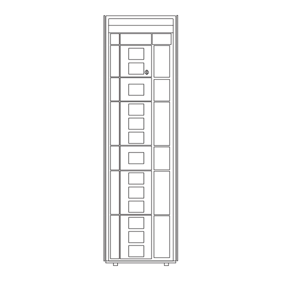
Page 15: Enterprise Modular Library E-Series, Model 245E
10448 See Model 103e figure Redundant power supply module (optional) Tape drive expansion module Tape drives Card cage expansion module Cable management features Viewing window Card cage module fans Load port (10-cartridge capacity) Redundant card cage power supplies Primary power supply module Figure 2 Enterprise Modular Library E-Series, Model 245e Enterprise Modular Library E-Series user guide... -
Page 16: Example Of A Fully Expanded Enterprise Modular Library E-Series
10449 Figure 3 Example of a fully expanded Enterprise Modular Library E-Series Library overview... -
Page 17: Base Module
Base module The 12U base module (see Figure 1) resides below the 2U space at the top of the rack reserved for customer use. The module contains a total of 103 LTO slots. Nine of these slots can be configured as reserved, and five slots are configurable within a load port through the use of a removable magazine. -
Page 18: Library Load Ports On 42U Configuration
9)—A single slot, 6U-wide cPCI board, having two 2-Gbps FC ports for connecting to the SAN, along with four 2-Gbps FC ports to connect up to four HP Ultrium tape drives. • An empty card slot reserved for future use. -
Page 19: Base Module Card Cage
10459 Base module card cage Library robotics controller Interface Manager card Adapter panel HP StorageWorks e2400-FC 2G interface controller Figure 6 Base module card cage FAULT STANDBY ACTIVE <Reverify text> 10420 Private Ethernet port (not used) Reserved port (not used) -
Page 20: Hp Storageworks Interface Manager Card
Tape drive FC port 1 Serial port Tape drive FC port 0 Power indicator FC port 1 (connection to host or switch) Figure 9 HP StorageWorks e2400-FC 2G interface controller 10415 Fibre Channel connector Mounting bracket with captive screw Figure 10 Ultrium tape drive... -
Page 21: Expansion Modules
On the back, the module contains one primary power supply with a slot provided for another optional redundant power supply. Up to four HP Ultrium tape drives can be installed on the module. Cable management features are provided for cable routing and dressing. -
Page 22: Card Cage Expansion Module
Card cage expansion module The card cage expansion module (Figure 12) is a 4U chassis that contains 48 permanent LTO slots and space for additional interface controllers. This module must be located directly below the 8U tape drive expansion module in a 24U library configuration. The number of usable slots depends on whether it is the lowest vertically-placed module in the library. -
Page 23: Functional Description
Fibre Channel switch Operator control panel e2400-FC 2G interface controller (up to 4) Serial connection Interface Manager card Telnet connection HP Ultrium tape drives (up to 16) Management station Library robotics controller Library boundary Figure 13 EML network In addition to receiving traffic from the interface controllers, the Interface Manager card receives command and diagnostic requests over an Ethernet connection from three other possible sources. -
Page 24: Controller Cards
HP StorageWorks e2400-FC 2G interface controller The e2400-FC 2G interface controller is an HP proprietary card that provides Fibre Channel connectivity for the tape drives and robotics in the SAN. Commands, data, and status information are transferred to and from this controller, from hosts, the robotics unit, and the tape drives. -
Page 25: Tape Drives
* Values assume a 2:1 compression ratio Data cartridges and cleaning cartridges are specifically formatted for use with Ultrium drives. To order Ultrium media, see ”Ordering HP tape cartridges and bar code label packs” on page 123. Operator control panel The OCP displays library status information and allows you to access the library menus with a touch screen. -
Page 26: Lto Slots
LTO slots All the modules that make up the library contain a mapping for arrays of LTO slots (or cells) for cartridges and tape drives. Each module has a different number of available slots, but a common numbering scheme for identifying the slot location. Some slots may not be available in the lowest library module when the floor is installed. -
Page 27: Base Module Slot Mapping
10439 Robot park zone Slots unavailable for use when module is last in library and has floor installed Array targets Tape drives Reserved slots Expansion identification label Software demarcation between upper and lower modules for slot counting purposes Load port Slots available for data cartridges Column numbering Figure 14... -
Page 28: Drive Expansion Module Slot Mapping
10440 Tape drives Slots available for data cartridges Column numbering Array targets Expansion identification label Slots unavailable for use when module is last in library and has floor installed Load port Figure 15 Drive expansion module slot mapping 10442 Slots available for data cartridges Expansion identification label Array targets Column numbering... -
Page 29: Hp Storageworks Command View Tl
HP StorageWorks Library and Tape Tools HP StorageWorks Library and Tape Tools (L&TT) is a collection of storage hardware management and diagnostic tools assembled into a single, convenient program. L&TT offers a GUI or command screen interface (CSI), allowing you to perform the following functions with the EML: •... - Page 30 • New versions of L&TT • New firmware files for connected devices • New device-specific functionality (such as new or updated tests) for connected devices For more information on L&TT, access http://www.hp.com/support/tapetools. Library overview...
-
Page 31: Installing The Library
2 Installing the Library This chapter describes how to unpack the HP StorageWorks Enterprise Modular Library (EML) E-Series, and install, cable, and configure components. The chapter topics are: • Selecting an installation location, page 31 • Receiving and unpacking, page 33 •... -
Page 32: Power Requirements
2) insufficient conductor ampacity that could result in overheating with potential personal injury and/or property damage; and 3) fracturing resulting in the internal contacts being exposed, which potentially could subject the user to a shock hazard. HP disclaims all liability in the event a non-HP approved power cord is used. -
Page 33: Receiving And Unpacking
Receiving and unpacking This section explains how to examine and unpack the library, and move it to its final installation location. The library is shipped in packing materials designed to protect it from damage during transit. These instructions help ensure that the library continues to be safeguarded after it arrives at the installation site. Tools needed for unpacking These tools are needed for unpacking and setting up the library: •... -
Page 34: Minimum Floor Space Requirements-Unpacking Site
NOTE: Figure 17 shows the minimum floor space required by the library at its unboxing site. Unboxing the library requires a minimum of 122 cm (4 ft) on all (1) sides. Side (2), used for the unloading ramp, requires 3.05 m (10 ft). The minimum height required for unpacking the library is 2.16 m (85 in). 10414 122 cm (4 ft) 3.05 m (10 ft) -
Page 35: Removing The Box Top Cover
Lift the cardboard box top cover straight up, and remove it from the box (see Figure 19). gl01002 Figure 19 Removing the box top cover Remove the cardboard box retaining clips (see Figure 20). gl01003 Figure 20 Removing the box retaining clips Enterprise Modular Library E-Series user guide... - Page 36 Remove the two cardboard sides around the rack (see Figure 21). Take the ramp (1) assembly off the pallet, and set it aside temporarily. gl01004 Ramp assembly Figure 21 Removing the cardboard sides Remove the four corner posts on each corner of the rack (see Figure 22).
-
Page 37: Removing Plastic Bag Over Rack
Remove the plastic bag covering the rack (see Figure 23). gl01006 Figure 23 Removing plastic bag over rack Unbolt and remove the four hold-down brackets securing the rack to the pallet (see Figure 24). gl01007 Figure 24 Unbolt rack hold-down brackets Enterprise Modular Library E-Series user guide... - Page 38 10.Remove the ramp assembly from its container. Using the single and double arrows marked on each ramp leg and the pallet, match the ramp arrows to the pallet and press into place (see Figure 25). gl01008 Figure 25 Attaching the ramp assembly WARNING! Two people are required to navigate the rack off the pallet.
-
Page 39: Positioning The Library
For a native Fibre Channel (FC) environment, you need the following: • One or more Ultrium tape drives (these come preinstalled in one orderable EML configuration) • One HP StorageWorks e2400-FC 2G interface controller for every four tape drives (comes preinstalled in one configuration) •... -
Page 40: Installing Tape Drives
Remove drive cover plates NOTE: HP recommends that tape drives be installed from top to bottom, with no gaps between drive openings. For example, a configuration using four tape drives would start at the first slot at the top of the rack and use the first four drive openings. -
Page 41: Installing The Hp Storageworks E2400-Fc 2G Interface Controllers
28). 10460 Figure 28 Tighten the mounting bracket captive screw Installing the HP StorageWorks e2400-FC 2G interface controllers CAUTION: Parts can be damaged by ESD. Keep parts in their containers until needed. Ensure that you are properly grounded when touching static-sensitive components. -
Page 42: Interface Controller Locations
Identify the proper slot in the card cage for the e2400-FC 2G interface controller. One must be installed in the base module card cage, and up to three can be installed in the card cage expansion module (see Figure 29). 10461 Interface controller cards Figure 29... -
Page 43: Cabling The Library
Cabling the library Cabling the HP StorageWorks e2400-FC 2G interface controllers The following procedure describes how to cable the e2400-FC 2G interface controllers: NOTE: Each e2400-FC 2G interface controller card ships with an Ethernet cable. The tape drives ship with a fiber optic cable. These parts are needed for the following procedures. -
Page 44: Cabling The Interface Manager Card
Cabling the Interface Manager card Ethernet connections to the Interface Manager card from the e2400-FC 2G interface controllers were made in ”Cabling the HP StorageWorks e2400-FC 2G interface controllers” on page 43. To complete cabling for the Interface Manager card: Plug one end of an Ethernet cable into the CASCADE port of the Interface Manager card and plug the other end into the PUBLIC port on the library robotics controller. -
Page 45: Installation Checklist
Command View TL, which is hosted on a management station. Read the HP StorageWorks Interface Manager and Command View TL documentation for information on installing and configuring version 1.5.5 or later on the EML. This documentation can be obtained at http://www.hp.com/support/cvtl. - Page 46 Installing the Library...
-
Page 47: Preparation For Use
The misuse and misunderstanding of bar code technology can result in backup and restore failures. To ensure that your bar codes meet HP quality standards, always purchase them from approved suppliers and never print bar code labels yourself. For more information, see the order form provided with... -
Page 48: Ultrium Bar Code Labels
Always use the proper bar code labels for your drive technology. An L2 identifier (Ultrium 460) or L3 identifier (Ultrium 960) is located at the end of the 8-character HP Ultrium bar code labels on data cartridges. The universal LTO cleaning cartridges have a CLN and L1 media identifier on the label. -
Page 49: Setting The Write-Protect Switch
Insertion arrow Write protect switch Figure 34 Write-protecting HP Ultrium tape cartridges Inserting tape cartridges into permanent slots The preferred method of loading tape cartridges into the library is through the load port. Inserting tapes through the front library door, though not suggested, should only be done when bulk loading. The use of the load port improves inventory time and working with independent software vendor (ISV) applications. -
Page 50: Removing The Robot Shipping Restraints
Retain the straps with other packing materials for use when transporting the library in the future Close the front library door. Setting the IP address for the HP StorageWorks Interface Manager card The Interface Manager card must be configured with a network IP address before the EML can properly function. -
Page 51: Eml Configuration Through The Ocp
EML configuration through the OCP Use the OCP to configure library settings before first use. After the library is powered up, configure these settings as described in ”Configuration screen” on page 61: • Administrative password • Load ports • Network settings •... - Page 52 Preparation for use...
-
Page 53: Library Operation
4 Library operation This chapter describes operating procedures for the Enterprise Modular Library (EML) E-Series. The topics in this chapter are: • Powering on the library, page 53 • Initialization, page 53 • Front door interlock, page 54 • Inserting tape cartridges into the load port, page 54 •... -
Page 54: Front Door Interlock
TIP: The library inventory process is faster when bar code labels are used on all your tape cartridges, and the library is configured to only use bar code labels. Front door interlock The library front door cannot be opened until a password-protected command to unlock the door is made through the OCP. -
Page 55: Using The Ocp
Using the OCP The OCP is an LCD screen located on the front of the library that is operated by touch. The icons, text, and tabs on the OCP allow you to obtain information about the library, execute library commands, and test library functions. -
Page 56: Home Screen
OCP tabs and status bar After touching the Home screen, you are presented with a navigation screen containing a status bar to the left of an HP logo, two rows of tabs, and an area for detailed screen information in the center (see Figure 38). -
Page 57: Timeouts
Five navigation tabs can be displayed at the bottom of the screen. One of the tabs can be the thumbtack (in or out) that was discussed in ”OCP icons” on page 55. The remaining tabs are: • Help—Displays help text for features appearing on that screen. •... -
Page 58: Ocp Functions
- Panel Firmware Version Individual Drive Status - Turn Backlight Off All Drive Summary Run Demo Interface Controller Status > - Interface Controller 1-4 HP Support Info Interface Manager Status Event Log Type Service Menu > Selection Contact View Library... -
Page 59: Status Screen
Status screen The Status screen (Figure 40) provides access to the current state of every EML component. Table 4 describes the information you can obtain from these status screens. Power supplies, load ports, tape drives, and interface controllers are all numbered from top to bottom in the rack. -
Page 60: Status Screen Functions
Table 4 Status screen functions (continued) Function Description Component Status Identifies the status of the overall library and individual components: • Library and Robotics—Displays library and robotics characteristics, and drive odometer. The odometer counts the number of loads for each drive. The load count is reset when a drive is replaced. -
Page 61: Configuration Screen
Change Password—The library ships with a null password. Passwords must be set to exactly eight characters, consisting of the numbers 0 through 9 and the period character. If you forget your password, contact HP support. HP support can generate a temporary password that will allow you to access the library. -
Page 62: Operations Screen
Operations screen The Operations screen (Figure 42) provides access to screens that allow you to unlock load ports, unlock the library door, reboot the library, move tapes, clean drives, and run administrative tests. Table 6 describes the operations that can be performed with these screens. Figure 42 OCP Operations screen Table 6... - Page 63 Table 6 Operations screen functions (continued) Function Description Run Admin Tests Performs the following tests: • Screen • Align Screen—Touch and release the screen near the rectangle in the center. As you approach the rectangle at some point, it changes color. The color change takes place when the border of the rectangle is touched.
-
Page 64: Support Screen
Support screen The Support screen (Figure 43) provides access to screens showing HP support information, service tasks, contact information, and allows you to display the library time. Table 7 describes the support information that can be obtained with these screens. -
Page 65: Controls And Indicators
Controls and indicators This section illustrates and describes the function of the controls and indicators on the EML. HP StorageWorks e2400-FC 2G Interface Controller card Figure 44 Table 8 show and describe the indicators located on the FC interface controller card. -
Page 66: Hp Storageworks Interface Manager Card
HP StorageWorks Interface Manager card Figure 45 Table 9 show and describe the control and indicators located on the FC interface controller card. gl01012 Figure 45 Interface Manager card reset and indicators Table 9 Interface Manager card reset and indicators... -
Page 67: Library Robotics Controller
Library robotics controller Figure 46 Table 8 show and describe the control and indicators located on the FC interface controller card. 10470 Figure 46 Library robotics controller indicators Table 10 Library robotics controller indicators Index No. Control/indicator Function EJECT OK LED Not used. -
Page 68: Hp Storageworks Ultrium Tape Drive
HP StorageWorks Ultrium tape drive Figure 47 Table 11 show and describe the indicator located on back of the HP Ultrium 460 tape drive. 10444 Figure 47 HP Ultrium tape drive indicator Table 11 HP Ultrium tape drive indicator Index No. -
Page 69: Library Main Power Switch
Library main power switch Figure 48 Table 12 show and describe the function of the library main power switch located at the back of the library at the top of the base module. 10445 Figure 48 Library main power switch control Table 12 Library main power switch control Index... -
Page 70: Base Module (Or Tape Drive Expansion Module) Power Supply
Base module (or tape drive expansion module) power supply Figure 49 Table 13 show and describe the indicator located on the autoranging power supply. 10446 Figure 49 Autoranging power supply indicator Table 13 Autoranging power supply indicator Index Indicator Function Power LED When lit (green), indicates that all four DC outputs and the fan speed are within specification, and the AC boost circuit is active. -
Page 71: Card Cage Expansion Module Power Supply
Card cage expansion module power supply Figure 50 Table 14 show and describe the function of the indicators located on the power supply in the card cage expansion module. 10450 Figure 50 Card cage expansion module power supply indicators Table 14 Card cage expansion module power supply indicators Index Control/indicator... -
Page 72: Power Distribution Unit
Power distribution unit Figure 51 Table 15 show and describe the function of the control and indicators located on the power distribution unit and the attached extension bars (power strips). 10451 Figure 51 Power distribution unit controls and indicator Table 15 Power distribution unit controls and indicator Index Control/indicator... -
Page 73: Maintenance
Interface Manager, and the management station. Any firmware updates should be performed with Command View TL. To use the Web-based GUI or command line interface for library diagnostics, see the HP StorageWorks Interface Manager and Command View TL user guide. -
Page 74: Troubleshooting
Troubleshooting An incorrect installation or configuration can cause platform problems. In this case, the library appears to be operating normally, but no data can be interchanged, or performance is poor. You also might or might not get an error code on the operator control panel (OCP). To identify an error caused by this type of problem, check your installation and configuration setup. -
Page 75: Startup Problems
Startup problems Table 17 describes corrective actions for problems which occur during startup. Table 17 Startup problems Problem Corrective action The library does not power on. Verify that: • The power cord is connected to a grounded electrical outlet. • Each PDU power switch is on, as well as the switch on the power strips. - Page 76 Table 17 Startup problems (continued) Problem Corrective action 0000: End of Text Open the library door and check the picker for a tape cartridge. If so, remove the tape and place it into an empty slot. Close the library door to initiate an inventory. One or more tape drives fail during startup.
-
Page 77: Ocp Problems
Confirm that the power is on. • Use Command View TL software or the Interface Manager CLI to check for errors. See the HP StorageWorks Interface Manager and Command View TL user guide. The OCP does not respond to touch. -
Page 78: Robotics Problems
Robotics problems Table 19 describes corrective actions for robotics problems. Table 19 Robotics problems Problem Corrective action The robot does not move at power on. • Verify that all internal shipping restraints have been removed. • Check that the library front door is closed. •... -
Page 79: Operating Problems
Operating problems Table 20 describes the corrective action for problems that occur during library operation. Table 20 Problems during library operation Problem Corrective action The host computer cannot communicate • Verify that the host computer was added to the Secure Manager with the library. -
Page 80: Tape Drive Problems
Eject button on the drive in question. The tape drive reports a • Try using a new tape. read/write error. • Clean the drive. • Test the drive with HP StorageWorks L&TT. Maintenance... -
Page 81: Interface Manager Card Problems
(CLI). These CLI commands can be used to diagnose problems. You can access the CLI either through a direct RS-232 serial connection or by using Telnet over the LAN. Refer to the HP StorageWorks Interface Manager and Command View TL user guide for instructions on using the CLI. Table 22 describes common symptoms relating to the Interface Manager card and how to resolve them. -
Page 82: Fibre Channel Interface Controller Problems
Table 22 Common Interface Manager issues (continued) Symptom Possible cause Solution Command View TL Incompatible browser • Verify that you are using a minimum of Microsoft Internet does not run in the version or Java support Explorer 6.0 SP1 or later, or Netscape Navigator 6.2 or browser. -
Page 83: Basic Troubleshooting
Verifying devices HP recommends using Command View TL to verify that the devices are functional. Verifying the host configuration In some cases, the FC HBA or host device driver may not be working properly. Check the configuration of these elements. -
Page 84: Verifying Hba Device Driver Information
Check the release notes for the device driver to see if there are any specific issues or a required configuration. Also, ensure that you are using the current version of the HBA driver. Older applications can have expectations about what constitutes a valid SCSI ID, and thus may not correctly handle certain mappings. -
Page 85: Removal And Replacement
Removal and replacement This section contains procedures for removing and replacing items that are end-user replaceable. Before randomly replacing suspect components, see the troubleshooting section to isolate a problem to that component. Afterwards, see ”Controls and indicators” on page 65 to verify the component is functioning normally. -
Page 86: Hp Storageworks Interface Manager Card
Verify that the library robotics controller ACTIVE indicator is lit (see Figure 46 on page 67). Close the rear rack door. HP StorageWorks Interface Manager card 340213-001 (Interface Manager card) Part Number 342215-001 (Memory Module) Bottom card cage slot in the base module... -
Page 87: Removing The Memory Module From The Interface Manager Card
Because all the configuration settings of the Interface Manager card are stored in the memory module that you replaced earlier, your replacement Interface Manager card retains the configuration of the original card. To verify or change these settings, see the HP StorageWorks Interface Manager and Command View TL user guide. -
Page 88: Hp Storageworks E2400-Fc 2G Interface Controller
10464 Required tools A #1 Phillips screwdriver is required for this procedure. Replacing an HP StorageWorks e2400-FC 2G interface controller To remove the interface controller: Open the back door of the library. Identify the e2400-FC 2G interface controller to be replaced. -
Page 89: Base Module (Or Tape Drive Expansion Unit Module) Power Supply
Close the back door of the library. Use the Interface Manager CLI or the HP StorageWorks Command View TL to verify detection of the new controller, and to perform configuration and firmware updates, if necessary. The interface controller replacement procedure is complete. -
Page 90: Screws Securing Power Supply To Base Module
Remove the two 6-32x3/8 Torx screws securing the power supply to the base or expansion module with a T-15 screwdriver (see Figure 53). 10466 Figure 53 Screws securing power supply to base module Pull the power supply handle to remove the power supply. WARNING! The power supply can be hot. -
Page 91: Card Cage Expansion Module Power Supply
If power was removed to the library, turn on the library main power switch. Close the back door of the library. The power supply replacement procedure is complete. Card cage expansion module power supply 375816-001 Part number Bottom of the card cage expansion module Location •... -
Page 92: Hp Storageworks Ultrium Tape Drive
HP StorageWorks Ultrium tape drive 375817-001 (Ultrium 460) Part number 381676-001 (Ultrium 960) • Hot-swappable Characteristics • 1/2 inch cartridge tape drive Writes data to and reads data from Linear Tape-Open (LTO) Function cartridges HP Ultrium 460 or gl01014 Required tools A flat blade screwdriver is required for this procedure. -
Page 93: Connecting The Fc Cable Into The New Drive
Interface Manager and Command View TL user guide for detailed procedures. Close the back door of the library. If necessary, upgrade the drive firmware using the Interface Manager CLI. See the HP StorageWorks Interface Manager and Command View TL user guide for detailed procedures on upgrading drive firmware. -
Page 94: Periodic And Routine Maintenance
80 percent. For longer tape cartridge life, store the tape cartridge at 40 percent to 60 percent relative humidity. • Use only HP qualified bar code labels. Apply them only in the designated areas of the tape cartridge, and do not apply more than one per cartridge. •... -
Page 95: Cleaning Ultrium Tape Drives
Ultrium tape drives have been developed to have a minimal cleaning requirement. • An HP Ultrium universal cleaning cartridge can be used up to 50 times. If you are using an older HP Ultrium cleaning cartridge, check the documentation that came with your media. - Page 96 Maintenance...
-
Page 97: Moving The Library
CAUTION: Moving or shipping the library without proper packing materials can result in damage to library components. HP strongly recommends that an HP authorized service representative move a library to another location. Checking the new installation site Check the new installation site for the library using the guidelines found in ”Selecting an installation... -
Page 98: Preparing The Library For Long-Distance Relocation
Preparing the library for long-distance relocation Unload all tape cartridges from the tape drives using your application software. Power off the library. Unlock and open the front door. Remove all tape cartridges from the library bins. Carefully pack all tapes for shipment. Install shipping restraints on the robot (see Figure 35 on page 50 for location). -
Page 99: Preparing The Library For Operation
Place the library on the shock pallet: a. Raise the library support feet. b. With the help of at least one person, roll the library to a position in front of the pallet ramp. c. Roll the library onto the pallet. Secure the library: a. - Page 100 100 Moving the library...
-
Page 101: A Specifications And Characteristics
A Specifications and characteristics This appendix describes the allowable configurations for the Enterprise Modular Library (EML) E-Series and the physical, electrical, and environmental characteristics of the library. Table 24 EML configurations Maximum Configurable Configurable Number of Height in slots load port reserved possible Configuration... -
Page 102: Library Component Specifications
Table 25 Library component specifications Characteristic Specification HP 10642 rack with 1 PDU Physical: Weight 114.84 kg (253 lb) Dimensions (HxDxW) 199.9 x 100.8 x 61.0 cm (78.7 x 39.7 x 24 in) Electrical: AC voltage range 200–240 V, 50/60 Hz... - Page 103 Main power supply Weight 2.3 kg (5.4 lb) Card cage expansion module power supply Weight 0.8 kg (1.8 lb) HP LTO Ultrium drive and tray Weight 3.6 kg (7.9 lb) LTO Ultrium cartridge Weight 220 g (7.8 oz) HP StorageWorks e2400-FC 2G interface...
-
Page 104: Library Environmental Specifications
Ultrium Generation 2, 3 HP classifies the performance of the HP StorageWorks Ultrium 960 as 80 x 1000 x 1000 bytes per second—80 MB/sec (that is, to base 10) in common with most other disk and tape drive vendors. Most applications, however, measure performance as 1024 x 1024 bytes per second. -
Page 105: B Regulatory Compliance Notices
B Regulatory compliance notices This appendix contains regulatory notices for the HP StorageWorks Enterprise Modular Library (EML) E-Series. Regulatory compliance identification numbers For the purpose of regulatory compliance certifications and identification, this product has been assigned a unique regulatory model number. The regulatory model number can be found on the product nameplate label, along with all required approval markings and information. -
Page 106: Dutch Battery Statement
- N'essayez pas de court-circuiter les bornes de la pile ou de jeter cette dernière dans le feu ou l'eau. - Remplacez les piles exclusivement par des pièces de rechange HP prévues pour ce produit. Les piles, modules de batteries et accumulateurs ne doivent pas être jetés avec les déchets ménagers. -
Page 107: German Battery Statement
Le batterie e gli accumulatori non devono essere smaltiti insieme ai rifiuti domestici. Per procedere al riciclaggio o al corretto smaltimento, utilizzare il sistema di raccolta pubblico dei rifiuti o restituirli a HP, ai Partner Ufficiali HP o ai relativi rappresentanti. -
Page 108: Japanese Battery Statement
Las baterías, los paquetes de baterías y los acumuladores no se deben eliminar junto con los desperdicios generales de la casa. Con el fin de tirarlos al contenedor de reciclaje adecuado, utilice los sistemas públicos de recogida o devuélvalas a HP, un distribuidor autorizado de HP o sus agentes. -
Page 109: Federal Communications Commission Notice
Federal Communications Commission notice Part 15 of the Federal Communications Commission (FCC) Rules and Regulations has established Radio Frequency (RF) emission limits to provide an interference-free radio frequency spectrum. Many electronic devices, including computers, generate RF energy incidental to their intended function and are, therefore, covered by these rules. -
Page 110: Declaration Of Conformity For Products Marked With The Fcc Logo, United States Only
Declaration of Conformity for products marked with the FCC logo, United States only. This device complies with Part 15 of the FCC Rules. Operation is subject to the following two conditions: (1) this device may not cause harmful interference, and (2) this device must accept any interference received, including interference that may cause undesired operation. -
Page 111: European Union Notice
European Union notice Products bearing the CE marking comply with the EMC Directive (89/336/EEC) and the Low Voltage Directive (73/23/EEC) issued by the Commission of the European Community. Compliance with these directives implies conformity to the following European Norms (in parentheses are the equivalent international standards and regulations): •... -
Page 112: Korean Notices
Korean notices Class A equipment Class B equipment Taiwanese notices BSMI Class A notice 112 Regulatory compliance notices... -
Page 113: Taiwan Battery Recycle Statement
• Allow only HP Authorized Service technicians to repair the unit. The Center for Devices and Radiological Health (CDRH) of the U.S. Food and Drug Administration implemented regulations for laser products on August 2, 1976. These regulations apply to laser products manufactured from August 1, 1976. -
Page 114: French Laser Notice
être effectuée par l'utilisateur. - Tout contrôle, réglage ou procédure autre que ceux décrits dans ce chapitre ne doivent pas être effectués par l'utilisateur. - Seuls les Mainteneurs Agréés HP sont habilités à réparer l'appareil laser. German laser notice VORSICHT: Dieses Gerät enthält möglicherweise einen Laser, der nach... -
Page 115: Japanese Laser Notice
- No realice más operaciones de control, ajustes o manipulaciones en el dispositivo láser que los aquí especificados. - Sólo permita reparar la unidad a los agentes del servicio técnico autorizado HP. Enterprise Modular Library E-Series user guide 115... -
Page 116: Recycling Notices
Recycling notices Disposal of waste equipment by users in private household in the European Union This symbol on the product or on its packaging indicates that this product must not be disposed of with your other household waste. Instead, it is your responsibility to dispose of your waste equipment by handing it over to a designated collection point for recycling of waste electrical and electronic equipment. -
Page 117: Dutch Notice
Dutch notice Verwijdering van afgedankte apparatuur door privé-gebruikers in de Europese Unie Dit symbool op het product of de verpakking geeft aan dat dit product niet mag worden gedeponeerd bij het normale huishoudelijke afval. U bent zelf verantwoordelijk voor het inleveren van uw afgedankte apparatuur bij een inzamelingspunt voor het recyclen van oude elektrische en elektronische apparatuur. -
Page 118: French Notice
French notice Élimination des appareils mis au rebut par les ménages dans l'Union européenne Le symbole apposé sur ce produit ou sur son emballage indique que ce produit ne doit pas être jeté avec les déchets ménagers ordinaires. Il est de votre responsabilité... -
Page 119: Hungarian Notice
Hungarian notice Italian notice Smaltimento delle apparecchiature da parte di privati nel territorio dell'Unione Europea Questo simbolo presente sul prodotto o sulla sua confezione indica che il prodotto non può essere smaltito insieme ai rifiuti domestici. È responsabilità dell'utente smaltire le apparecchiature consegnandole presso un punto di raccolta designato al riciclo e allo smaltimento di apparecchiature elettriche ed elettroniche. -
Page 120: Lithuanian Notice
Para obter mais informações sobre locais que reciclam esse tipo de material, entre em contato com o escritório da HP em sua cidade, com o serviço de coleta de lixo ou com a loja em que o produto foi adquirido. -
Page 121: Slovakian Notice
Slovakian notice Slovenian notice Spanish notice Eliminación de residuos de equipos eléctricos y electrónicos por parte de usuarios particulares en la Unión Europea Este símbolo en el producto o en su envase indica que no debe eliminarse junto con los desperdicios generales de la casa. Es responsabilidad del usuario eliminar los residuos de este tipo depositándolos en un "punto limpio"... -
Page 122: Swedish Notice
Swedish notice Bortskaffande av avfallsprodukter från användare i privathushåll inom Europeiska Unionen Om den här symbolen visas på produkten eller förpackningen betyder det att produkten inte får slängas på samma ställe som hushållssopor. I stället är det ditt ansvar att bortskaffa avfallet genom att överlämna det till ett uppsamlingsställe avsett för återvinning av avfall från elektriska och elektroniska produkter. -
Page 123: C Ordering Hp Tape Cartridges And Bar Code Label Packs
HP recommends using HP tape cartridges in your HP StorageWorks tape library. See Table 29 for a list of HP media, prelabeled media, and bar code label packs. These can be purchased directly from HP, or through an authorized reseller or sales office. •... - Page 124 Bar code label pack, read/write Q2007A (100 data labels, 10 cleaning labels) • Bar code label pack, WORM Q2008A (100 data labels, 10 cleaning labels) Capacity values assume a 2:1 compression ratio 124 Ordering HP tape cartridges and bar code label packs...
-
Page 125: D Installing A Redundant Pdu
This appendix provides suggestions as to when an additional, redundant power distribution unit (PDU) should be installed in the HP StorageWorks Enterprise Modular Library (EML) E-Series. The EML product comes with one PDU installed. For a variety of reasons, it may be desirable or necessary to add a second PDU to the EML rack. -
Page 126: Power Rating
Power rating As was the case with leakage current, if equipment is added to the EML rack from other sources, it is your responsibility to ensure the power rating of the PDU and power cords are not exceeded by the load of this additional equipment. -
Page 127: Installation Of Redundant Pdu Components
10535 Power strip #2 Power strip #4 Redundant PDU (#2) Caster boss Figure 57 Redundant PDU and power strip placement Installation of redundant PDU components Refer to the instructions provided with your redundant PDU for installation steps. After installation, dress all cords with cable ties. - Page 128 128 Installing a redundant PDU...
-
Page 129: Glossary
CompactPCI (cPCI®) Industry standard bus used for card-to-card bus expansion. containment box A box in the HP Enterprise Modular Library robotics unit that holds the lift flex cable. The cable retracts into the box as the table is raised. data cartridge A term used to distinguish a cartridge onto which a tape drive may write data from a cartridge used for cleaning purposes. - Page 130 • Card cage expansion module (optional) HP (unit of measure) Horizontal pitch. A measurement of the width of a chassis. EML circuit card assemblies sitting horizontally in card cages are measured vertically in these units where one HP is 5.08 millimeters (0.2 inches).
- Page 131 Ultrium 460 tape drives (LTO-2) are HP’s second generation of LTO tape drives and the Ultrium 960 tape drives (LTO-3) are third generation tape drives.
- Page 132 3U cards are 100 x 160 mm (3.94 x 6.3 inches) and 6U cards are 230 x 160 mm (9.187 x 6.3 inches). The HP StorageWorks Interface Manager card is considered 4U wide with dimensions of 161.9 x 157.3 mm (6.4 x 6.2 inches).
-
Page 133: Index
HP Configuration screen configurations, EML Contact Information screen bar code labels contrast adjustment configuring use controls and indicators information tracked... - Page 134 Subscriber’s choice web site depiction technical support functional description HP Support Info screen lithium battery removal and replacement library, relocating lift drive assembly import/export slots lift flex cable Indentity Screen...
- Page 135 load port configuring installing redundant functional description requirements inserting tape cartridges physical description unlocking picker assembly positioning the library slots power cables, connecting technology power distribution unit power off library power rating, PDU power requirements magazine power strips depiction power supply functional description autoranging inserting cartridges...
- Page 136 Ultrium tape drives warning, rack stability startup problems web sites static IP address Command View ESL Status screen HP documentation Subscriber’s choice, HP HP storage Support screen HP Subscriber’s choice symbols in text write-protect switch, tape cartridges Taiwanese notices tape cartridges...
Need help?
Do you have a question about the E Series and is the answer not in the manual?
Questions and answers