Table of Contents
Advertisement
Quick Start Guide
PTX10008 Packet Transport Router
IN THIS GUIDE
PTX10008 System Overview
NOTE:
The PTX10008 Quick Start is designed to get your new router up and running in short order. For a full
description of all the components, the specifications, and unabridged installation instructions, see the PTX10008
Packet Transport Router Hardware Guide.
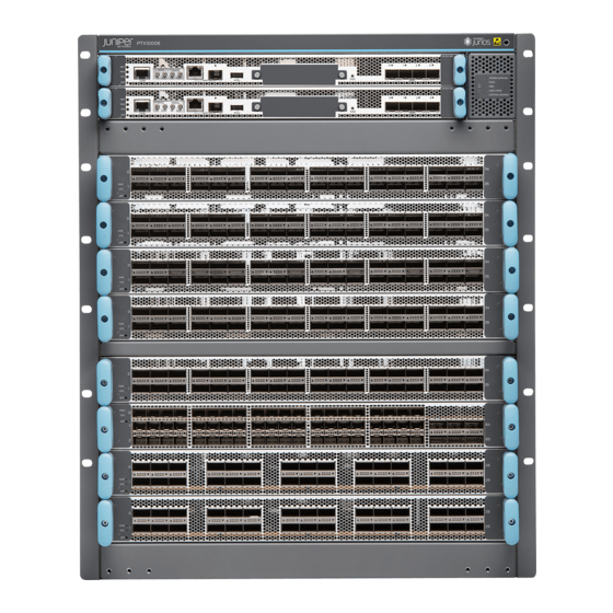
The Juniper Networks PTX10008 Packet Transport Router enables cloud and data center operators to smoothly transition
from 10-Gigabit and 40-Gigabit Ethernet networks to 100-Gigabit and 400-Gigabit Ethernet high-performance networks.
This flexible, 13 rack unit (13-U) modular chassis has eight line card slots that can support a maximum of 1152 10-Gigabit
Advertisement
Table of Contents

Related Manuals for Juniper PTX10008


Summary of Contents for Juniper PTX10008
-
Page 1: Table Of Contents
PTX10008 System Overview NOTE: The PTX10008 Quick Start is designed to get your new router up and running in short order. For a full description of all the components, the specifications, and unabridged installation instructions, see the PTX10008 Packet Transport Router Hardware Guide. -
Page 2: Step 1-Prepare The Site
Before you install the PTX10008, make sure the site meets all of the rack, power, cooling, and clearance requirements. Rack-Mount Requirements The PTX10008 router chassis is designed to be installed in standard 19-in. wide four-post racks that are spaced at 1 U (1.75 in. or 4.45 cm) increments. - Page 3 34.2 in. (86.8 cm) If you are mounting a PTX10008 in a rack with other equipment, ensure that the exhaust from other equipment does not blow into the intake vents of the chassis. The air intake to cool the chassis is located in the vents of the line cards and Routing and Control Boards (RCBs). Air flows passes from the line cards and RCBs, through the switch interface boards (SIBs), and exists from the fans trays and the power supplies.
-
Page 4: Step 2-Unpacking The Ptx10008
The chassis is maximally protected inside the shipping box. Do not unpack it until you are ready to begin installation. Ensure that you have the following parts and tools available to unpack the PTX10008: A 13/32 in. (10 mm) open-end or socket wrench to remove the bracket bolts from the shipping pallet A box cutter or packing knife to slice open the nylon straps and tape that seal the crate and boxes The chassis ships in a cardboard box that has a two-layer wooden pallet base with foam cushioning between the layers. - Page 5 To unpack the chassis (see Figure Figure 4: Shipping Crate and Accessory Box 1. Move the shipping box to a staging area as close to the installation site as possible. While the chassis is bolted to the pallet, you can use a forklift or pallet jack to move it. Make sure there is enough space to remove components from the chassis.
-
Page 6: Step 3-Mount The Chassis In The Rack
13. Save the shipping box and packing materials in case you need to move or ship the router at a later time. Step 3–Mount the Chassis in the Rack Install the Mounting Hardware | 7 Mount the PTX10008 in a 4-Post Rack Using a Mechanical Lift | 9... - Page 7 To mount the chassis on a four-post rack, you must first install the mounting hardware in the rack. The PTX10008 router comes with a four-piece set of brackets that supports the chassis in the rack.
- Page 8 4. Position one of the rear brackets at the left rear of the rack on the same level as the left base bracket, so that the rear bracket overlaps with the left bracket. The screw holes for connecting the base and rear brackets should overlap. Use four mounting screws appropriate for your rack to attach the rear bracket to the rack.
- Page 9 Mount the PTX10008 in a 4-Post Rack Using a Mechanical Lift Because of the router's size and weight, we strongly recommend using a mechanical lift to install the PTX10008. If you do not have a mechanical lift available, see the alternative instructions for manual mounting in the PTX10008 Packet Routing Hardware Guide.
- Page 10 Figure 7: Loading the PTX10008 into a Rack Using a Mechanical Lift 3. Using the lift, align the router in front of the rack, centering it in front of the base brackets. 4. Lift the chassis approximately 0.75 in. (1.9 cm) above the surface of the base brackets. Align the chassis as close as possible to the base brackets.
-
Page 11: Step 4-Install The Line Cards
Figure 8: Attaching the Chassis Flanges to the Rack 6. Move the lift away from the rack. 7. Attach the chassis to the rack by installing a mounting screw through the open flange holes and rack, starting from the bottom. 8. - Page 12 1. Attach the ESD grounding strap to your bare wrist and connect the strap to the ESD point on the router chassis. The ESD point is located above the status LED panel on the front of the router chassis. See Figure Figure 9: ESD Point on PTX10008 Chassis Front ESD point —...
- Page 13 Figure 10: Removing the Cover Panel for a Line Card CAUTION: Do not lift the line card by holding the edge connectors or the handles on the faceplate. Neither the handles or the edge connectors can support the weight of the line card. Lifting the line card by the handles or edge connectors might bend them, which would prevent the line cards from being properly seated in the chassis.
-
Page 14: Step 5-Install The Front Panel
Step 5–Install the Front Panel The front panel is required on the PTX10008 router to protect fiber optic cabling and to provide additional protection from electromagnetic interference (EMI). The front panel can be installed with or without the optional cable management system. - Page 15 To install the front panel: 1. Attach an ESD grounding strap to your bare wrist and connect the strap to one of the ESD points on the chassis. 2. Remove the plastic bag that is taped to the front panel, which holds the brackets and screws. 3.
- Page 16 Figure 15: Attaching Front Panel Brackets on a PTX10008 6. Use the final two mounting screws to attach a latch bracket to the top right of the chassis frame so there are brackets on all four corners of the front of the chassis.
- Page 17 Figure 16: Front Panel Installation on a PTX10008 To install the (optional) air filter in the front panel: 1. Attach an ESD grounding strap to your bare wrist and connect the strap to one of the ESD points on the chassis.
- Page 18 Figure 17: Air Filter Frame in a PTX10008 Front Panel Air filter frame — 3. Hold the air filter with both hands and insert it into the front panel until it stops. See Figure...
-
Page 19: Step 6-Connect Power To The Chassis
Figure 18: Inserting the AIr Filter into a PTX10008 Front Panel Air filter — 4. Move the air filter frame over the front panel and turn the knob on the air filter frame clockwise back in place. NOTE: You must replace the filter every 6 months. - Page 20 A Phillips screwdriver to tighten the two screws that are mounted on the chassis. An AC-powered PTX10008 gains additional grounding when you plug the power supply in the router into a grounded AC power outlet by using an AC power cord appropriate for your geographical location.
- Page 21 5. Place the chassis grounding lug and cable over the PEM nuts with the cable connection pointing to the left. See Figure Figure 20: Connecting a Grounding Cable to the PTX10008 6. Place the two screws over the grounding lug and grounding cable.
- Page 22 1. Attach the electrostatic discharge (ESD) grounding strap to your bare wrist, and connect the strap to the ESD point on the chassis. There is an ESD point located next to the protective earthing terminal and below PSU 5 on the PTX10008...
- Page 23 11. Tighten the captive screw by turning it clockwise by using the Phillips (+) screwdriver, number 1. When the screw is completely tight, the latch locks into the router chassis. Figure 22: Installing a JNP10K-PWR-AC Power Supply in a PTX10008 Keep latch in open position during installation.
- Page 24 INP1 (lower receptacle) and only uses INP2 (top receptacle) at fail over. See Figure Figure 23: Proper Load Balancing for JNP10K-PWR-AC Power Cables on PTX10008 WARNING: Ensure that the power cords do not block access to router components or drape where people can trip on them.
- Page 25 Figure 24: Power Cord and Retainer Clip Enable switch for INP1 appears as INP0 in output. Enable switch for INP2 appears as INP1 in output. — — WARNING: Ensure that the power cords do not block access to router components or drape where people can trip on them.
- Page 26 1. Attach the electrostatic discharge (ESD) grounding strap to your bare wrist, and connect the strap to the ESD point on the chassis. There is an ESD point located next to the protective earthing terminal and below PSU5 on the PTX10008...
- Page 27 10. Tighten the captive screw by turning it clockwise by using the Phillips (+) screwdriver, number 1. When the screw is completely tight, the latch locks into the router chassis. Figure 26: Installing a JNP10K-PWR-AC2 in a PTX10008 NOTE: The power supply fans will start immediately when inserted into the chassis, even though a feed is not yet connected.
- Page 28 Figure 27: Proper Load Balancing for JNP10K-PWR-AC2 Power Cables on PTX10008 12. For each power cable, insert the end of the cable with the Anderson connector into the JNP10K-PWR-AC2 power supply module. The connector snaps and locks the cable into position.
- Page 29 The JNP10K-PWR-DC power supply in a PTX10008 chassis is a hot-removable and hot-insertable field-replaceable unit (FRU). You can install up to 6 JNP10K-PWR-DC power supplies in a PTX10008 router chassis. All power supplies install in the rear of the chassis in the slots along the left side of the chassis.
- Page 30 1. Attach the electrostatic discharge (ESD) grounding strap to your bare wrist, and connect the strap to the ESD point on the chassis. There is an ESD point located next to the protective earthing terminal and below PSU 5 on the PTX10008...
- Page 31 Figure 28: Removing the Plastic Cable Cover on a JNP10K-PWR-DC Power Supply 6. Remove the nuts from each DC power input terminal, using the 13/32 in. (10 mm) nut driver or socket wrench to loosen the nuts. 7. Ensure that the power source circuit breaker is open so that the voltage across the DC power source cable leads is 0 V and that the cable leads do not become active while you are connecting DC power.
- Page 32 CAUTION: You must ensure that power connections maintain the proper polarity. The power source cables might be labeled (+) and (–) to indicate their polarity. There is no standard color coding for DC power cables. 10. Install each power cable lug on the DC power input terminal, securing it with the nut (see Figure 29).
- Page 33 Figure 30 for PTX10008 installations). Figure 30: Removing the PSU Cover on a PTX10008 13. Unscrew the captive screw in the counterclockwise direction by using the Phillips (+) screwdriver, number 1. 14. Pull the captive screw away from the faceplate of the power supply to release the latch.
- Page 34 Figure 31: Installing a JNP10K-PWR-DC Power Supply in a PTX10008 NOTE: Ensure that the ejector is fully open to avoid scratching the chassis. Scratches Ejector fully open Ejector closed 19. Route INP1 cables to a power source and INP2 to another power source. The JNP10K-PWR-DC shares power, so if power dips on one input, the power supply is able to load balance internally.
- Page 35 Set both enable switches to the | (on) position when using both source inputs. When not using source redundancy, set the unused source to the off (O) position. The LED turns red and indicates an error if a source input is not in use and the enable switch is on (|).
- Page 36 1. Attach the electrostatic discharge (ESD) grounding strap to your bare wrist, and connect the strap to the ESD point on the chassis. There is an ESD point located next to the protective earthing terminal and below PSU 5 on the PTX10008...
- Page 37 5. Remove the plastic cable cover from the power input terminals by using the Phillips (+) screwdriver, number 2, to loosen the screws (see Figure 33). Figure 33: Removing the Plastic Cable Cover on a JNP10K-PWR-DC2 Power Supply 6. Remove the nuts from each DC power input terminal, using the 13/32 in. (10 mm) nut driver or socket wrench to loosen the nuts.
- Page 38 9. Install each power cable lug on the DC power input terminal, securing it with the nut (see Figure 34). Apply between 24 in.-lb (2.7 N-m) and 25 in.-lb (2.8 N-m) of torque to each nut. (Use the 13/32 in. [10 mm] nut driver or socket wrench.) a.
- Page 39 Figure 35: Removing the Power Supply Cover on a PTX10008 12. Unscrew the captive screw in the counterclockwise direction by using the Phillips (+) screwdriver, number 1. 13. Rotate the captive screw away from the faceplate of the power supply to release the latch.
- Page 40 Figure 36: Installing a JNP10K-PWR-DC2 in PTX10008 17. Route INP1 cables to a power source and INP2 to another power source. The JNP10K-PWR-DC shares power, so if power dips on one input, the power supply is able to load balance internally.
-
Page 41: Step 7-Connecting To The Network
Step 7–Connecting to the Network You can configure and manage the PTX10008 by using a dedicated console. Every control board has a console port with an RJ-45 connector. Use the console port to connect the device to the management console or to a console server. The console port accepts a cable with an RJ-45 connector. -
Page 42: Step 8-Perform The Initial Configuration
Step 8–Perform the Initial Configuration You must perform the initial configuration of the PTX10008 through the console port using the CLI or through Zero Touch Provisioning (ZTP). In order to use ZTP to provision the device, you must have access to a Dynamic Host Control Protocol (DHCP) server, and a File Transfer Protocol (anonymous FTP), Hypertext Transfer Protocol (HTTP), or Trivial File Transfer Protocol (TFTP) server on which the software image and configuration files are stored. - Page 43 4. Enter configuration mode. root> configure 5. Add a password to the root administration user account. [edit] root@# set system root-authentication plain-text-password New password: password Retype new password: password 6. (Optional) Configure the name of the router. If the name includes spaces, enclose the name in quotation marks (“ ”). [edit] root@# set system host-name host-name 7.
-
Page 44: Safety Warnings Summary
Failure to observe these safety warnings can result in personal injury or death. Permit only trained and qualified personnel to install or replace router components. Perform only the procedures described in this quick start and the PTX10008 router documentation. Other services must be performed only by authorized service personnel. - Page 45 The weight of a chassis varies by the configuration. A chassis spare is the lightest at 273 lb (123.8 kg) and the weight goes up to 421 lb (191 kg) on the PTX10008-PREM3. Installing the PTX10008 router in a rack or cabinet requires either a mechanical lift or three people to lift the router and another person to secure it to the rack.
Need help?
Do you have a question about the PTX10008 and is the answer not in the manual?
Questions and answers