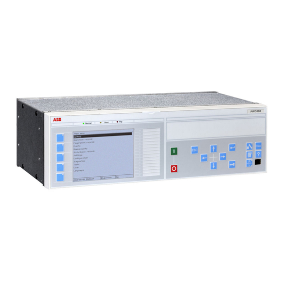
Hitachi Relion 650 Series Technical Manual

Hitachi Relion 650 Series Technical Manual

Hide thumbs Also See for Relion 650 Series:
Table of Contents

Advertisement

Quick Links

EU Declaration of Conformity
REC650
Declaration
®
Relion
650 series
Switchsync™ PWC600 Version 1.2
Technical Manual
Directives
Application of
the objects
Harmonized
Standards
Authorization
© Hitachi Energy 2021. All rights reserved.
We Hitachi Energy Sweden AB, SE-721 59 Västerås, Sweden, declare
under our sole responsibility that the family of apparatus:
Bay Control
to which this declaration relates is in conformity with the following relevant
Union harmonization legislations:
2014/30/EU
EMC Directive
Official Journal of the EU (L96, 29/03/2014, p. 79-106)
2014/35/EU
Low Voltage Directive
Official Journal of the EU (L96, 29/03/2014, p. 357-374)
The product is intended for use in the industrial environment and to protect high
voltage or high-power apparatus, and thus normally used in a harsh
electromagnetic environment near high voltage apparatus.
References to the relevant harmonized standards or other technical
specifications to which conformity is declared:
EN 60255-26: 2013
EN 60255-27: 2014
Signed for and on
behalf of:
Document identity
1MRK 000 612-66
Revision
Type: REC650, Ver. 1.0
acc. to Product Guide
1MRK 511211-BEN
Electromagnetic compatibility requirements
Product safety requirements
Marko Kovacic (PM)
1/1
C
Date

Advertisement

Table of Contents
loading

Summary of Contents for Hitachi Relion 650 Series

  • Page 1 EU Declaration of Conformity REC650 Document identity 1MRK 000 612-66 Revision Declaration We Hitachi Energy Sweden AB, SE-721 59 Västerås, Sweden, declare under our sole responsibility that the family of apparatus: ® Relion 650 series Bay Control Type: REC650, Ver. 1.0 Switchsync™...
  • Page 3 Document ID: 1MRK 511 557-UEN Issued: November 2021 Revision: A Product version: 1.2 © 2021 Hitachi Energy. All rights reserved.
  • Page 4 Copyright This document and parts thereof must not be reproduced or copied without written permission from Hitachi Energy, and the contents thereof must not be imparted to a third party, nor used for any unauthorized purpose. The software and hardware described in this document is furnished under a license and may be used or disclosed only in accordance with the terms of such license.
  • Page 5 This document has been carefully checked by Hitachi Energy but deviations cannot be completely ruled out. In case any errors are detected, the reader is kindly requested to notify the manufacturer.
  • Page 6 Directive 2004/108/EC) and concerning electrical equipment for use within specified voltage limits (Low-voltage directive 2006/95/EC). This conformity is the result of tests conducted by Hitachi Energy in accordance with the product standard EN 60255-26 for the EMC directive, and with the product standards EN 60255-1 and EN 60255-27 for the low voltage directive.
  • Page 7: Table Of Contents

    Local HMI elements......................39 5.1.1 Display..........................39 5.1.2 LEDs..........................41 5.1.3 Keypad..........................42 Local HMI screen........................ 43 5.2.1 Identification........................43 5.2.2 Settings..........................43 Local HMI signals........................ 43 5.3.1 Identification........................43 5.3.2 Function block........................43 5.3.3 Signals..........................44 Technical Manual © 2021 Hitachi Energy. All rights reserved.
  • Page 8 Functionality ........................67 9.1.3 Function block........................67 9.1.4 Signals..........................67 9.1.5 Settings..........................68 9.1.6 Operation principle ......................68 IEC 61850 generic communication I/O functions DPGGIO..........69 9.2.1 Identification........................69 9.2.2 Functionality ........................69 Technical Manual © 2021 Hitachi Energy. All rights reserved.
  • Page 9 Settings........................... 100 10.1.6 Operation principle......................101 10.1.6.1 Limit module.......................101 10.1.6.2 Chart function......................102 10.1.6.3 Equation function....................... 102 10.1.6.4 Status information...................... 103 10.2 Double point input status time monitoring DPISTTIM............103 10.2.1 Identification........................103 Technical Manual © 2021 Hitachi Energy. All rights reserved.
  • Page 10 INVERTERQT function block ..................125 11.1.2.4 Pulse timer function block PULSTIMERQT..............126 11.1.2.5 XORQT function block....................127 11.1.2.6 Settable timer function block TIMERSETQT..............128 11.1.2.7 ANDQT function block ....................129 11.1.2.8 Set-reset function block SRMEMORYQT..............130 Technical Manual © 2021 Hitachi Energy. All rights reserved.
  • Page 11 11.6.6 Operation principle ......................143 11.7 Logical function to determine the minimum and maximum value MINMAX ..... 143 11.7.1 Identification........................143 11.7.2 Functionality ........................144 11.7.3 Function block......................... 144 11.7.4 Signals..........................144 Technical Manual © 2021 Hitachi Energy. All rights reserved.
  • Page 12 Monitored data......................158 12.1.3 Phase current measurement CMMXU................158 12.1.3.1 Identification ......................158 12.1.3.2 Function block......................159 12.1.3.3 Signals........................159 12.1.3.4 Settings........................159 12.1.3.5 Monitored data......................160 12.1.4 Phase-phase voltage measurement VMMXU..............160 Technical Manual © 2021 Hitachi Energy. All rights reserved.
  • Page 13 Monitored data........................ 179 12.2.7 Operation principle......................179 12.2.7.1 Reporting........................179 12.2.8 Technical data......................... 180 12.3 Limit counter L4UFCNT.....................180 12.3.1 Function description......................180 12.3.2 Introduction ........................180 12.3.3 Function block......................... 180 12.3.4 Signals..........................180 12.3.5 Settings........................... 181 Technical Manual © 2021 Hitachi Energy. All rights reserved.
  • Page 14 Recording times......................204 12.4.6.9 Analog signals......................205 12.4.6.10 Binary signals......................207 12.4.6.11 Trigger signals......................207 12.4.6.12 Post Retrigger......................208 12.4.7 Technical data......................... 208 12.5 Indications......................... 209 12.5.1 Functionality ........................209 12.5.2 Function block......................... 209 12.5.3 Signals..........................209 Technical Manual © 2021 Hitachi Energy. All rights reserved.
  • Page 15 Operation principle ......................217 12.11 IEC 61850 generic communication I/O functions 16 inputs SP16GGIO......217 12.11.1 Identification........................217 12.11.2 Functionality ........................217 12.11.3 Function block......................... 218 12.11.4 Signals..........................218 12.11.5 Settings........................... 218 12.11.6 MonitoredData.........................219 Technical Manual © 2021 Hitachi Energy. All rights reserved.
  • Page 16 Compensation of circuit breaker switching times CBCOMP..........236 12.16.1 Identification ........................236 12.16.2 Functionality ........................236 12.16.3 Function block......................... 237 12.16.4 Signals..........................238 12.16.5 Settings........................... 241 12.16.6 Monitored data........................ 242 12.16.7 Operation principle......................243 12.16.7.1 Compensation mode....................244 Technical Manual © 2021 Hitachi Energy. All rights reserved.
  • Page 17 Reset logic......................... 313 12.18.7.20 Temperature handling logic..................314 12.18.7.21 Learning active mode....................315 12.19 Operation log trigger generator OPLOGTRIG..............315 12.19.1 Identification........................315 12.19.2 Functionality (Application summary)................315 12.19.3 Function block......................... 316 12.19.4 Signals..........................316 Technical Manual © 2021 Hitachi Energy. All rights reserved.
  • Page 18 Core logic........................342 Section 13 Station communication................345 13.1 IEC 61850-8-1 communication protocol ................345 13.1.1 Identification........................345 13.1.2 Functionality ........................345 13.1.3 Communication interfaces and protocols ............... 346 13.1.4 Settings........................... 346 Technical Manual © 2021 Hitachi Energy. All rights reserved.
  • Page 19 13.7.1 Introduction ........................354 13.7.2 Identification........................355 13.7.3 Function block......................... 355 13.7.4 Signals..........................355 13.7.5 Settings........................... 356 13.7.6 Operation principle......................356 13.7.6.1 Signal identification ....................358 13.7.6.2 Time synchronization....................359 13.7.6.3 Alarm signals......................359 Technical Manual © 2021 Hitachi Energy. All rights reserved.
  • Page 20 Time system, summer time begin DSTBEGIN..............371 14.2.4.1 Identification....................... 371 14.2.4.2 Settings........................372 14.2.5 Time system, summer time ends DSTEND..............372 14.2.5.1 Identification....................... 372 14.2.5.2 Settings........................373 14.2.6 Time zone from UTC TIMEZONE................... 373 14.2.6.1 Identification....................... 373 Technical Manual © 2021 Hitachi Energy. All rights reserved.
  • Page 21 Load and Grounding Selection...................387 14.6 Change lock function CHNGLCK ..................389 14.6.1 Identification........................389 14.6.2 Functionality ........................389 14.6.3 Function block......................... 389 14.6.4 Signals..........................389 14.6.5 Settings........................... 389 14.6.6 Operation principle ......................390 Technical Manual © 2021 Hitachi Energy. All rights reserved.
  • Page 22 Authority check ATHCHCK....................403 14.14.1 Identification........................403 14.14.2 Functionality ........................403 14.14.3 Settings........................... 404 14.14.4 Operation principle ......................404 14.14.4.1 Authorization handling in the IED................405 14.15 Authority management AUTHMAN................... 405 14.15.1 Identification........................405 Technical Manual © 2021 Hitachi Energy. All rights reserved.
  • Page 23 14.20.3 Settings........................... 415 14.20.4 Operation principle......................415 Section 15 IED physical connections................. 417 15.1 Protective earth connections .................... 417 15.2 Inputs..........................417 15.2.1 Measuring inputs ......................417 15.2.2 Auxiliary supply voltage input..................418 Technical Manual © 2021 Hitachi Energy. All rights reserved.
  • Page 24 Environmental conditions and tests ..................436 17.12 Electromagnetic compatibility tests .................. 436 17.13 Insulation tests ......................... 438 17.14 Mechanical tests .......................438 17.15 Product safety ........................438 17.16 EMC compliance ......................439 Section 18 Glossary..................... 441 Technical Manual © 2021 Hitachi Energy. All rights reserved.
  • Page 25: Introduction

    Communication protocol manual, IEC 61850 1MRK 511 554-UEN Cyber Security deployment guidelines 1MRK 511 555-UEN User Manual 1MRK 511 556-UEN Technical manual 1MRK 511 557-UEN MICS 1MRG 035 293 Table continues on next page Technical Manual © 2021 Hitachi Energy. All rights reserved.
  • Page 26: Document Revision History

    1MRG 035 547 TICS 1MRG 035 548 1) Switchsync PWC600 1.2 is based on Relion 650 series, version 1.3. So the PIXIT and TICS from Relion 650 series, version 1.3 are applicable for Switchsync PWC600 1.2 too. 1.3.2 Document revision history...
  • Page 27: Available Functions

    Configurable logic blocks Q/T PULSETIMERQT Configurable logic blocks Q/T INVALIDQT Configurable logic blocks Q/T INDCOMBSPQT Configurable logic blocks Q/T INDEXTSPQT Configurable logic blocks Q/T FXDSIGN Fixed signal function block Table continues on next page Technical Manual © 2021 Hitachi Energy. All rights reserved.
  • Page 28 Advanced circuit breaker operation and monitoring CBLEARN Circuit breaker contact operation time learning function GFGDE General Function to map to GDE CLROPLOG Clear operation log data OPLOGTRIG Trigger operation record TRAFOSWT Transformer Switching 2-T01 2-T01 Technical Manual © 2021 Hitachi Energy. All rights reserved.
  • Page 29: Station Communication

    Time synchronization TIMEZONE Time synchronization IRIG-B Time synchronization SYNCHPPS Time synchronization SETGRPS Setting group handling ACTVGRP Parameter setting groups TESTMODE Test Mode Functionality CHNGLCK Change lock function Table continues on next page Technical Manual © 2021 Hitachi Energy. All rights reserved.
  • Page 30 Basic part for CP HW LED indication module GRP3_LED15 LHMICTRL Local HMI signals LANGUAGE Local human machine language OPENCLOSE_LED LHMI LEDs for open and close keys Table continues on next page Technical Manual © 2021 Hitachi Energy. All rights reserved.
  • Page 31 Local HMI functions SCREEN Local HMI Local human machine screen behavior FNKEYTY1 - LCD part for HMI Function Keys Control module FNKEYTY5 FNKEYMD1 - LCD part for HMI Function Keys Control module FNKEYMD5 Technical Manual © 2021 Hitachi Energy. All rights reserved.
  • Page 33: Analog Inputs

    For directional functions the directional conventions are defined as follows (see Figure • Forward means the direction is into the object. • Reverse means the direction is out from the object. Technical Manual © 2021 Hitachi Energy. All rights reserved.
  • Page 34 The CT and VT ratings are entered in SST, under the Reference signals milestone. Channel names are assigned in the pre-configuration. Manual changes can be done under Main menu/Hardware / Analog modules in the Parameter Settings tool or on the LHMI or WHMI. Technical Manual © 2021 Hitachi Energy. All rights reserved.
  • Page 35: Settings

    MU3 - L2U MU3 - L3U MU3 - L4U MU4 - L1I MU4 - L2I MU4 - L3I MU4 - L4I MU4 - L1U MU4 - L2U MU4 - L3U MU4 - L4U Technical Manual © 2021 Hitachi Energy. All rights reserved.
  • Page 36 ToObject ToObject= towards protected object, ToObject FromObject= the opposite CTStarPoint3 FromObject ToObject ToObject= towards protected object, ToObject FromObject= the opposite CTStarPoint4 FromObject ToObject ToObject= towards protected object, ToObject FromObject= the opposite Technical Manual © 2021 Hitachi Energy. All rights reserved.
  • Page 37 MU1_4I_4U Non group settings (advanced) Name Values (Range) Unit Step Default Description SynchMode NoSynch Operation Synchronization mode Init Operation GUID-242C96FD-E2AA-4B57-AD66-79571D067FCB v1 MU2_4I_4U, MU3_4I_4U and MU4_4I_4U have the same settings as MU1_4I_4U. Technical Manual © 2021 Hitachi Energy. All rights reserved.
  • Page 39: Binary Inputs And Outputs

    OscillationTimex, where x is the number of the binary input of the module in question. For precision binary inputs, the filter parameters can be specified separately for On and Off status changes. Technical Manual © 2021 Hitachi Energy. All rights reserved.
  • Page 40: Settings

    0.005 Debounce time for input 7 OscillationCount7 0 - 255 Oscillation count for input 7 OscillationTime7 0.000 - 600.000 0.001 0.000 Oscillation time for input 7 Table continues on next page Technical Manual © 2021 Hitachi Energy. All rights reserved.
  • Page 41: Setting Parameters For Precision Binary Inputs

    Debounce time On for input 3 DebounceTimeOff3 0.0000 - 0.1270 0.0001 0.0050 Debounce time Off for input 3 OscillationCntOn3 0 - 255 OscillationCountOn for input 3 Table continues on next page Technical Manual © 2021 Hitachi Energy. All rights reserved.
  • Page 42 0 - 255 OscillationCountOff for input 8 OscillationTimeOn8 0.000 - 600.000 0.001 0.000 OscillationTimeOn for input 8 OscillationTimeOff8 0.000 - 600.000 0.001 0.000 OscillationTimeOff for input 8 Table continues on next page Technical Manual © 2021 Hitachi Energy. All rights reserved.
  • Page 43: Binary Outputs

    The BIO module provides 9 output relay contacts. Out of these, 3 are rated for making and carrying high currents. The remaining 6 contacts are intended for signaling; some of them share a common terminal, see the connection diagram for details. Technical Manual © 2021 Hitachi Energy. All rights reserved.
  • Page 44 To protect the trip circuit supervision circuits in the IED, the output contacts are provided with parallel transient voltage suppressors. The breakdown voltage of these suppressors is 400 ± 20 V DC. Technical Manual © 2021 Hitachi Energy. All rights reserved.
  • Page 45: Local Hmi

    The amount of characters and rows fitting the view depends on the character size and the view that is shown. The display view is divided into four basic areas. Technical Manual © 2021 Hitachi Energy. All rights reserved.
  • Page 46 Each function key has a LED indication that can be used as a feedback signal for the function key control action. The LED is connected to the required signal with PCM600. Technical Manual © 2021 Hitachi Energy. All rights reserved.
  • Page 47: Leds

    The LEDs can be configured with PCM600 and the operation mode can be selected with the LHMI or PCM600. In Switchsync PWC600, the functions and operation modes of the LEDs on page 1 are defined in the default pre-configuration. Technical Manual © 2021 Hitachi Energy. All rights reserved.
  • Page 48: Keypad

    1...5 Function key Close Open Escape Left Down Right User Log on Enter Remote/Local Uplink LED Ethernet communication port (RJ-45) Multipage Menu Clear Help Programmable alarm LEDs Protection status LEDs Technical Manual © 2021 Hitachi Energy. All rights reserved.
  • Page 49: Local Hmi Screen

    ANSI/IEEE C37.2 identification identification device number Local HMI signals LHMICTRL 5.3.2 Function block D0E5676T201305151403 v2 LHMICTRL CLRLEDS HMI-ON RED-S YELLOW-S YELLOW-F CLRPULSE LEDSCLRD IEC09000320-1-en.vsd D0E13174T201305151403 V1 EN-US Figure 7: LHMICTRL function block Technical Manual © 2021 Hitachi Energy. All rights reserved.
  • Page 50: Signals

    LEDs. Input and output signals of the function blocks are configured with PCM600. The input signal for each LED is selected individually using SMT Technical Manual © 2021 Hitachi Energy. All rights reserved.
  • Page 51: Function Block

    D0E5682T201305151403 v1 Table 14: LEDGEN Output signals Name Type Description NEWIND BOOLEAN New indication signal if any LED indication input is set BOOLEAN A pulse is provided when the LEDs are acknowledged Technical Manual © 2021 Hitachi Energy. All rights reserved.
  • Page 52: Settings

    LEDs. The function is positive edge triggered, not level triggered. Acknowledgment/reset is performed via button and menus on the LHMI. Technical Manual © 2021 Hitachi Energy. All rights reserved.
  • Page 53: Operating Sequence

    If inputs for two or more colors are active at the same time to one LED the priority is as described above. An example of the operation when two colors are activated in parallel is shown in Figure Technical Manual © 2021 Hitachi Energy. All rights reserved.
  • Page 54 Activating signal GREEN Activating signal RED Acknow IEC09000313_1_en.vsd D0E13162T201305151403 V1 EN-US Figure 14: Operating Sequence 3 (LatchedAck-F-S), 2 colors involved Technical Manual © 2021 Hitachi Energy. All rights reserved.
  • Page 55 Every LED is independent of the other LEDs in its operation. Technical Manual © 2021 Hitachi Energy. All rights reserved.
  • Page 56 LEDs set for sequence 6 are completely independent in its operation of LEDs set for other sequences. Timing diagram for sequence 6 D0E5431T201305151403 v1 Figure 19 shows the timing diagram for two indications within one disturbance. Technical Manual © 2021 Hitachi Energy. All rights reserved.
  • Page 57 Figure 20: Operating sequence 6 (LatchedReset-S), two different disturbances Figure 21 shows the timing diagram when a new indication appears after the first one has reset but before tRestart has elapsed. Technical Manual © 2021 Hitachi Energy. All rights reserved.
  • Page 58 Disturbance tRestart Activating signal 1 Activating signal 2 LED 1 LED 2 Automatic reset Manual reset IEC01000242_2_en.vsd D0E10944T201305151403 V1 EN-US Figure 22: Operating sequence 6 (LatchedReset-S), manual reset Technical Manual © 2021 Hitachi Energy. All rights reserved.
  • Page 59: Function Keys

    FNKEYMD1 Input signals Name Type Default Description LEDCTL1 BOOLEAN LED control input for function key D0E5691T201305151403 v1 Table 18: FNKEYMD1 Output signals Name Type Description FKEYOUT1 BOOLEAN Output controlled by function key Technical Manual © 2021 Hitachi Energy. All rights reserved.
  • Page 60: Settings

    0 (low) and 1 (high). Key presses shorter than the detection period are ignored. Key press 0.5 s 0.5 s 0.5 s Output IEC17000251-1-en.vsd IEC17000251 V1 EN-US Figure 24: Sequence diagram for setting TOGGLE Technical Manual © 2021 Hitachi Energy. All rights reserved.
  • Page 61: Input Function

    The binary input LEDCTL is active only when Type is set to ‘Control’. In this mode, the status (ON/ OFF) of the yellow LED on the function key directly follows the status of LEDCTL. This functionality is independent of the Mode setting. Technical Manual © 2021 Hitachi Energy. All rights reserved.
  • Page 63: Web Hmi (Whmi)

    If the time stamps of an operation record and a waveform record are within ±20 ms of each other, they are assumed to describe the same switching operation. In WHMI, this information is used for creating hyperlinks, to allow directly jumping between views. Technical Manual © 2021 Hitachi Energy. All rights reserved.
  • Page 65: Controlled Switching And Monitoring

    This switching strategy ensures low inrush currents and low transient voltages. Refer Equation 1 for relation of voltage across the capacitive load and current through it.   (Equation 1) GUID-54E449BA-4A65-447C-9803-1F589D393DE1 V2 EN-US Technical Manual © 2021 Hitachi Energy. All rights reserved.
  • Page 66 Technical Manual © 2021 Hitachi Energy. All rights reserved.
  • Page 67 A point-on-wave controller such as PWC600 analyzes the reference voltage signal and identifies a favorable switching target (D , at Technical Manual © 2021 Hitachi Energy. All rights reserved.
  • Page 68 Key parameters will also be logged for future analysis. Technical Manual © 2021 Hitachi Energy. All rights reserved.
  • Page 69 Controlled switching with current feedback Busbar Reference signal Input Output command command Mechanical Circuit feedback Switchsync breaker PWC600 Electrical feedback Load Load IEC17000166-1-en.vsdx IEC17000166 V1 EN-US Figure 31: Controlled switching with load voltage feedback Technical Manual © 2021 Hitachi Energy. All rights reserved.
  • Page 70 Coordination for Data logging & Compensation acquisition Temperature Logging L1\L2\L3 L1\L2\L3 trigger Electrical Feedback Current / Load voltage Data to be logged Mechanical Feedback IEC17000167 V3 EN-US Figure 32: Main application functions in PWC600 Technical Manual © 2021 Hitachi Energy. All rights reserved.
  • Page 71: Secondary System Supervision

    Default Description TCS_STATE BOOLEAN Trip circuit fail indication from I/O-card BLOCK BOOLEAN Block of function PID-1837-OUTPUTSIGNALS v14 Table 23: TCSSCBR Output signals Name Type Description ALARM BOOLEAN Trip circuit fault indication Technical Manual © 2021 Hitachi Energy. All rights reserved.
  • Page 72: Settings

    When the reset timer has reached the limit set by tReset and TCS_STATE is still 0, it resets the operation timer. This can be used to suppress short spikes in the supervision signal. Activation of the BLOCK input deactivates the ALARM output and resets the internal timers. Technical Manual © 2021 Hitachi Energy. All rights reserved.
  • Page 73: Control

    Name Type Description BLOCKED BOOLEAN The function is active but the functionality is blocked POSITION INTEGER Position indication, integer POS1 BOOLEAN Position 1 indication, logical signal Table continues on next page Technical Manual © 2021 Hitachi Energy. All rights reserved.
  • Page 74: Settings

    Both indications and commands use double-point representation, where a combination of two binary signals represents the switch position. The following table shows the relationship between IPOS1/ IPOS2 inputs and the corresponding positions. Technical Manual © 2021 Hitachi Energy. All rights reserved.
  • Page 75: Iec 61850 Generic Communication I/O Functions Dpggio

    Name Type Default Description OPEN BOOLEAN Open indication CLOSE BOOLEAN Close indication VALID BOOLEAN Valid indication D0E6533T201305151403 v1 Table 30: DPGGIO Output signals Name Type Description POSITION INTEGER Double point indication Technical Manual © 2021 Hitachi Energy. All rights reserved.
  • Page 76: Settings

    The POW controller also takes into account the statistical nature of circuit breaker in terms of mechanical and Technical Manual © 2021 Hitachi Energy. All rights reserved.
  • Page 77 3-phase AC source and to a load. The IED determines optimal switching instants based on the user defined settings and thus issues close/open commands to the CB. Technical Manual © 2021 Hitachi Energy. All rights reserved.
  • Page 78: Function Block

    STCLANGL1 CBOPCAPIN STCLANGL2 LOADTYPE STCLANGL3 GROUNDING STOPANGL1 EXTSTGY STOPANGL2 LD1CLANL1 STOPANGL3 LD1CLANL2 OPREF LD1CLANL3 CNTRLDEL LD2CLANL1 LD2CLANL2 LD2CLANL3 IEC19000897 V2 EN-US Figure 36: Function block diagram * Denotes grouped input connections. Technical Manual © 2021 Hitachi Energy. All rights reserved.
  • Page 79: Signals

    Predicted pre-arcing time for closing of phase L3 COMPOFCL1 REAL Mechanical compensation offset for closing instant in phase L1 COMPOFCL2 REAL Mechanical compensation offset for closing instant in phase L2 Table continues on next page Technical Manual © 2021 Hitachi Energy. All rights reserved.
  • Page 80 Emergency trip indication for immediate trip operation OPBYPASS BOOLEAN Open command bypasses point-on-wave control CLBYPASS BOOLEAN Close command bypasses point-on-wave control BLKOPL1 BOOLEAN Open operation blocked in phase L1 Table continues on next page Technical Manual © 2021 Hitachi Energy. All rights reserved.
  • Page 81 Point-on-wave switching capability indication for phase L3 STCLANGL1 REAL Target current making angle for phase L1, in deg STCLANGL2 REAL Target current making angle for phase L2, in deg Table continues on next page Technical Manual © 2021 Hitachi Energy. All rights reserved.
  • Page 82: Settings

    Target contact separation angle (relative to OpenTargetL1) for L2 phase OpenTargetL3-L1 -1800 - 1800 Target contact separation angle (relative to OpenTargetL1) for L3 phase OpenRef Voltage Voltage Reference signal for controlled opening Current operations Technical Manual © 2021 Hitachi Energy. All rights reserved.
  • Page 83: Monitored Data

    Circuit breaker operating capability for 2=Open phase L2 3=Close-Open 4=Open-Close- Open 5=Close-Open- Close-Open CBOPCAPL3 INTEGER 1=None Circuit breaker operating capability for 2=Open phase L3 3=Close-Open 4=Open-Close- Open 5=Close-Open- Close-Open Table continues on next page Technical Manual © 2021 Hitachi Energy. All rights reserved.
  • Page 84: Operation Principle

    SSCPOW function can be enabled or disabled by the Operation setting. The overall functionality of the SSCPOW function is shown in Figure 37. This function operates on the sub-functional aspects described below. Technical Manual © 2021 Hitachi Energy. All rights reserved.
  • Page 85: Nominal Mechanical Breaker Operating Times

    Refer Section 9.3.7.4 a detailed elaboration. For an explanation on all the circuit breaker characteristics, refer to the chapter on ACBMSCBR function. Technical Manual © 2021 Hitachi Energy. All rights reserved.
  • Page 86: Reference Selection And Source Validation

    (see below). The function obtains status information of the healthiness of source at its inputs VOLREFOK or CURREFOK from other functions (usually ANSGPROC) and uses this information for its reference selection. Technical Manual © 2021 Hitachi Energy. All rights reserved.
  • Page 87: Controlled Switching Strategies

    For example; if OpenTargetL1 = 60°, OpenTargetL2-L1 = -120° and OpenTargetL3-L1 = 90°, the lead phase here is set as L2 and the contact separation instants are as shown in Figure Technical Manual © 2021 Hitachi Energy. All rights reserved.
  • Page 88 External (channel 2) current making target for phase L2, in electrical degrees relative to LD2CLANL1 LD2CLANL3 Input External (channel 2) current making target for phase L3, in electrical degrees relative to LD2CLANL1 Table continues on next page Technical Manual © 2021 Hitachi Energy. All rights reserved.
  • Page 89 Table 45 summarizes the handling of input close command for all load types. The outputs STCLANGL1, STCLANGL2 and STCLANGL3 are continuously updated with the closing target angle values displayed in Table Technical Manual © 2021 Hitachi Energy. All rights reserved.
  • Page 90 LD1CLANL3 = -60° ― Phase L3 -60° 120° 90° Energizing Energizing instant L3 instant L2 Energizing instant L1 Reference point IEC21000971 V1 EN-US Figure 39: Target energization instants for all three phases Technical Manual © 2021 Hitachi Energy. All rights reserved.
  • Page 91: Controlled Switching Operations

    For controlled closing of a CB, consider the reference voltage in Figure 40. When the user gives a CB closing command (CMDCLOSE input) at point A, which is at a random phase angle of the Technical Manual © 2021 Hitachi Energy. All rights reserved.
  • Page 92 ADAPTCLx is the adaptive correction value for previous targeting errors; [1] Latest zero crossing is the last zero crossing seen by the function prior to activation of the function CMDCLOSE input. Technical Manual © 2021 Hitachi Energy. All rights reserved.
  • Page 93 (based on the respective phase) is defined by: Contact separation target = OpenTargetL1, Contact separation target = OpenTargetL1 + OpenTargetL2-L1 –120° (based on positive going zero crossing of phase L2), and Technical Manual © 2021 Hitachi Energy. All rights reserved.
  • Page 94 GUID-4693DC74-AA70-4192-9460-8E045AB558A1 v2 Once the controlled switching commands are released by the function, the outputs must remain active for some time to guarantee reliable execution of the CB operation. SSCPOW uses a Technical Manual © 2021 Hitachi Energy. All rights reserved.
  • Page 95: Switching Command Handling

    The specific reaction to a received switching command is governed by different settings and inputs as shown in Table 47. Blocking an operation means that no switching command is forwarded to the CB. Bypass indicates operation of the CB without point-on-wave control. Technical Manual © 2021 Hitachi Energy. All rights reserved.
  • Page 96 Applicable for load types of (coupled) transformer. Table 48 describes the overall effect of these signals and settings on opening and closing operations for load types of capacitor, (coupled) reactor, transmission line, and power cable. Technical Manual © 2021 Hitachi Energy. All rights reserved.
  • Page 97 Open & Close Close (any) Controlled Bypassed Open & Close Close (any) Blocked Bypassed Open & Close Open (any) Blocked Controlled Open & Close Open (any) Bypassed Controlled Table continues on next page Technical Manual © 2021 Hitachi Energy. All rights reserved.
  • Page 98 No Bypass / (any) Block close Blocked block Open (any option for open) External / No Bypass / Bypass close Blocked block Open (any option for open) Table continues on next page Technical Manual © 2021 Hitachi Energy. All rights reserved.
  • Page 99 All the output commands are issued on three individual outputs for opening and three outputs for closing operations. These output signals include time stamp information to activate the IED’s static outputs (PBOs) on the PIO card at the specified times. Technical Manual © 2021 Hitachi Energy. All rights reserved.
  • Page 100: Waveform (Disturbance) Records

    Without any modification, SSCPOW further updates the received CB position status on its outputs SWTPOSLx. 9.3.7.10 Emergency Trip GUID-308DD7CB-E918-46FC-A68B-1CF8A3F14A7F v2 An emergency trip is an immediate trip or open operation issued by SSCPOW. The function issues an emergency trip when: Technical Manual © 2021 Hitachi Energy. All rights reserved.
  • Page 101: Generation Of Alarms

    This value is provided on the CNTRLDEL output. If the delay exceeds the MaxContDelay threshold, the TIMEEXED output is activated. This alarm is generated only when ContDelayExdAlm setting is enabled as shown in Table Technical Manual © 2021 Hitachi Energy. All rights reserved.
  • Page 102: Remote/Local Control

    Position evaluation (POS_EVAL) function converts the input position data signal POSITION, consisting of value, time and signal status, to binary signals OPENPOS or CLOSEPOS. The output signals are used by other functions in the interlocking scheme. Technical Manual © 2021 Hitachi Energy. All rights reserved.
  • Page 103: Function Block

    Description OPENPOS BOOLEAN Open position CLOSEPOS BOOLEAN Close position 9.4.6 Settings PID-1880-SETTINGS v2 The function does not have any settings available in Local HMI or Protection and Control IED Manager (PCM600). Technical Manual © 2021 Hitachi Energy. All rights reserved.
  • Page 105: General Calculation

    Warning signal for out of range output. ALARM BOOLEAN Alarm signal for out of range input OUTPUT REAL Output signal SENSTSOUT BOOLEAN Sensor status output ANGSCALE GROUP SIGNAL Group output containing scaled value and alarm Technical Manual © 2021 Hitachi Energy. All rights reserved.
  • Page 106: Settings

    Output value for curve point 5 -99999.9 - 99999.9 Output value for curve point 6 -99999.9 - 99999.9 Output value for curve point 7 -99999.9 - 99999.9 Output value for curve point 8 Technical Manual © 2021 Hitachi Energy. All rights reserved.
  • Page 107: Operation Principle

    The limit module limits the input value to the range between the low limit and the high limit values specified by the settings LowLimit and HighLimit. If the input value falls outside the range spanned by LowLimit and HighLimit: Technical Manual © 2021 Hitachi Energy. All rights reserved.
  • Page 108: Chart Function

    Set FnType to "Equation" mode to enable this functionality. In this mode, the output is calculated as a function of the input based on the constants declared in the following equation: + + × × c d e IECEQUATION-0092 V1 EN-US Where, Technical Manual © 2021 Hitachi Energy. All rights reserved.
  • Page 109: Status Information

    DPISTTIM function can be used for computing the idle times, that is, time since the last open and close operations of a switch. Technical Manual © 2021 Hitachi Energy. All rights reserved.
  • Page 110: Function Block

    Keep counting DefValue -999999.0 - Default value to be set upon reset 999999.0 depending on the errStsCountMode TimeScale milliSeconds milliSeconds Setting for output times scale selection Seconds Minutes Hours Technical Manual © 2021 Hitachi Energy. All rights reserved.
  • Page 111: Operation Principle

    • If ‘Keep counting’ is selected the counters continue counting the last valid status. Table 69 summarizes the behavior of the DPISTTIM function block. Technical Manual © 2021 Hitachi Energy. All rights reserved.
  • Page 112 Time count counters from last valid open → Keep counting closed status change Reset to default (Any) Time count from last invalid → closed status change Table continues on next page Technical Manual © 2021 Hitachi Energy. All rights reserved.
  • Page 113: Binary Status To Analog Conversion Binstsan

    • Summation: one or more inputs are high in a random order and the output is the cumulative sum of the scaled input values. Technical Manual © 2021 Hitachi Energy. All rights reserved.
  • Page 114: Function Block

    Table 71: BINSTSAN Output signals Name Type Description NOINP BOOLEAN Signal for input not detected ERROR BOOLEAN Signal for indicating wrong combination of inputs detected ANALOUT REAL Analog output after conversion Technical Manual © 2021 Hitachi Energy. All rights reserved.
  • Page 115: Settings

    The output signal value is used for further processing in other functions. The overall functionality is defined in the logic diagram as shown in Figure Technical Manual © 2021 Hitachi Energy. All rights reserved.
  • Page 116: Calculating Output Values Using 1 Of N Mode

    TRUE. If none of the inputs are high, the input is not detected and the NOINP output is set to TRUE. The output is set to the default output if ERROR and/or NOINP outputs are TRUE. The output evaluated as per the setting of input mode is as shown in Table Technical Manual © 2021 Hitachi Energy. All rights reserved.
  • Page 117: Calculating Output Values Using Incremental Mode

    NOINP output is set to TRUE. The output is set to the default output if ERROR and/or NOINP outputs are TRUE. The output evaluated as per the setting of input mode is as shown in Table Technical Manual © 2021 Hitachi Energy. All rights reserved.
  • Page 118: General Arithmetic Base Function Arithmet

    REALIN2 REALVALD REALVALD REALVALD INTIN1 INTIN1 INTIN1 INTOU T INTOU T INTOU T INTIN2 INTIN2 INTIN2 INTMODU INTMODU INTMODU REALOUT REALOUT REALOUT IEC19000932-2-en.vsdx IEC19000932 V2 EN-US Figure 49: Function Block Diagram Technical Manual © 2021 Hitachi Energy. All rights reserved.
  • Page 119: Signals

    AritmetType = "Addition" • REALOUT = REALIN1 + REALIN2 • INTOUT = INTIN1 + INTIN2 AritmetType = "Subtraction" • REALOUT = REALIN1 – REALIN2 • INTOUT = INTIN1 – INTIN2 AritmetType = "Multiplication" Technical Manual © 2021 Hitachi Energy. All rights reserved.
  • Page 120 REALOUT = (REALIN1 / Real limit divider) and REALVALD = 0. • For division of integer numbers, if the absolute value of INTIN2 is less or equal Int limit divider, INTOUT = (INTIN1 / Int limit divider) and INTVALD = 0. Technical Manual © 2021 Hitachi Energy. All rights reserved.
  • Page 121: Logic

    The function also propagates timestamp and quality of input signal. • XORQT XOR function block. The function also propagates timestamp and quality of input signals. Each block has two outputs where one is inverted. Technical Manual © 2021 Hitachi Energy. All rights reserved.
  • Page 122: Or Function Block

    One of the outputs is inverted. The output signal is 1 if at least one input signal is 1. Function block D0E6788T201305151403 v1 INPUT1 INPUT2 NOUT INPUT3 INPUT4 INPUT5 INPUT6 IEC09000288-1-en.vsd D0E13099T201305151403 V1 EN-US Figure 50: OR function block Technical Manual © 2021 Hitachi Energy. All rights reserved.
  • Page 123: Inverter Function Block Inverter

    Table 84: INVERTER Output signals Name Type Description BOOLEAN Output signal Settings D0E6904T201305151403 v1 The function does not have any parameters available in Local HMI or Protection and Control IED Manager (PCM600). Technical Manual © 2021 Hitachi Energy. All rights reserved.
  • Page 124: Pulsetimer Function Block

    Controllable gate function block GATE Functionality D0E6847T201305151403 v2 The GATE function block is used for controlling if a signal should pass from the input to the output or not, depending on the setting. Technical Manual © 2021 Hitachi Energy. All rights reserved.
  • Page 125: Exclusive Or Function Block Xor

    IEC09000292-1-en.vsd D0E13111T201305151403 V1 EN-US Figure 54: XOR function block Signals D0E7313T201305151403 v1 Table 91: XOR Input signals Name Type Default Description INPUT1 BOOLEAN Input signal 1 INPUT2 BOOLEAN Input signal 2 Technical Manual © 2021 Hitachi Energy. All rights reserved.
  • Page 126: Loop Delay Function Block Loopdelay

    Timer function block TIMERSET Functionality D0E6841T201305151403 v1 The function block TIMERSET has pick-up and drop-out delayed outputs related to the input signal. The timer has a settable time delay (t). Technical Manual © 2021 Hitachi Energy. All rights reserved.
  • Page 127: And Function Block

    0.000 - 90000.000 0.001 0.000 Delay for settable timer n 11.1.1.9 AND function block Identification D0E6882T201305151403 v1 Function description IEC 61850 IEC 60617 ANSI/IEEE C37.2 identification identification device number AND function block Technical Manual © 2021 Hitachi Energy. All rights reserved.
  • Page 128: Set-Reset Memory Function Block Srmemory

    The memory setting controls if the flip-flop after a power interruption will return to the state it had before or if it will be reset. In SRMEMORY, the SET input has priority over RESET input. Technical Manual © 2021 Hitachi Energy. All rights reserved.
  • Page 129: Reset-Set With Memory Function Block Rsmemory

    The memory setting controls if the flip-flop after a power interruption will return to the state it had before or if it will be reset. In RSMEMORY, the RESET input has priority over SET input. Technical Manual © 2021 Hitachi Energy. All rights reserved.
  • Page 130: Configurable Logic With Propagation Of Timestamp And Quality

    A number of logic blocks and timers with the capability to propagate timestamp and quality of the input signals are available. The function blocks assist the user to adapt the IED’s configuration to the specific application needs. Technical Manual © 2021 Hitachi Energy. All rights reserved.
  • Page 131: Orqt Function Block

    The function does not have any parameters available in Local HMI or Protection and Control IED Manager (PCM600). 11.1.2.3 INVERTERQT function block Identification GUID-8D9260C0-3E0D-40DE-A521-70834662A4D0 v1 Function description IEC 61850 IEC 60617 ANSI/IEEE C37.2 identification identification device number INVERTERQT function block INVERTERQT Technical Manual © 2021 Hitachi Energy. All rights reserved.
  • Page 132: Pulse Timer Function Block Pulstimerqt

    Function block GUID-A9E4A2DF-28A9-4082-A36D-964383F38896 v2 PULSETIMERQT INPUT IEC09000304-1-en.vsd IEC09000304 V1 EN-US Figure 63: PULSETIMERQT function block Signals PID-1081-INPUTSIGNALS v15 Table 112: PULSETIMERQT Input signals Name Type Default Description INPUT BOOLEAN Input signal Technical Manual © 2021 Hitachi Energy. All rights reserved.
  • Page 133: Xorqt Function Block

    Type Description BOOLEAN Output signal NOUT BOOLEAN Inverted output signal Settings GUID-50A2CEA0-2781-4C5F-B184-F09FC666876F v1 The function does not have any parameters available in Local HMI or Protection and Control IED Manager (PCM600). Technical Manual © 2021 Hitachi Energy. All rights reserved.
  • Page 134: Settable Timer Function Block Timersetqt

    Table 117: TIMERSETQT Input signals Name Type Default Description INPUT BOOLEAN Input signal PID-1083-OUTPUTSIGNALS v15 Table 118: TIMERSETQT Output signals Name Type Description BOOLEAN Output signal, pick-up delayed BOOLEAN Output signal, drop-out delayed Technical Manual © 2021 Hitachi Energy. All rights reserved.
  • Page 135: Andqt Function Block

    Type Description BOOLEAN Output signal NOUT BOOLEAN Inverted output signal Settings GUID-50A2CEA0-2781-4C5F-B184-F09FC666876F v1 The function does not have any parameters available in Local HMI or Protection and Control IED Manager (PCM600). Technical Manual © 2021 Hitachi Energy. All rights reserved.
  • Page 136: Set-Reset Function Block Srmemoryqt

    Default Description BOOLEAN Input signal to set RESET BOOLEAN Input signal to reset PID-1082-OUTPUTSIGNALS v15 Table 124: SRMEMORYQT Output signals Name Type Description BOOLEAN Output signal NOUT BOOLEAN Inverted output signal Technical Manual © 2021 Hitachi Energy. All rights reserved.
  • Page 137: Reset-Set Function Block Rsmemoryqt

    Default Description BOOLEAN Input signal to set RESET BOOLEAN Input signal to reset PID-1188-OUTPUTSIGNALS v15 Table 128: RSMEMORYQT Output signals Name Type Description BOOLEAN Output signal NOUT BOOLEAN Inverted output signal Technical Manual © 2021 Hitachi Energy. All rights reserved.
  • Page 138: Invalidqt Function Block

    Indication input 2 INPUT3 BOOLEAN Indication input 3 INPUT4 BOOLEAN Indication input 4 INPUT5 BOOLEAN Indication input 5 INPUT6 BOOLEAN Indication input 6 INPUT7 BOOLEAN Indication input 7 Table continues on next page Technical Manual © 2021 Hitachi Energy. All rights reserved.
  • Page 139: Indication Combining Single Position Function Block Indcombspqt

    SP_OUT output. State input bits are copied to the corresponding state part of SP_OUT output. If the state or value on the SP_OUT output changes, the Event bit in the state part is toggled. Technical Manual © 2021 Hitachi Energy. All rights reserved.
  • Page 140: Indication Extractor Single Position Function Block Indextspqt

    Value part of single position input is copied to SI_OUT output. Time part of single position input is copied to TIME output. State bits in common part and indication part of inputs signal is copied to the corresponding state output. Technical Manual © 2021 Hitachi Energy. All rights reserved.
  • Page 141: Fixed Signals Fxdsign

    IED, either for forcing the unused inputs in other function blocks to a certain level/ value, or for creating certain logic. Boolean, integer, floating point, string, and group types of signals are available. Technical Manual © 2021 Hitachi Energy. All rights reserved.
  • Page 142: Function Block

    STRNULL is a string, fixed to an empty string (null) value • ZEROSMPL is the channel index of an analog signal, fixed to 0 value • GRP_OFF is a group signal, fixed to 0 value Technical Manual © 2021 Hitachi Energy. All rights reserved.
  • Page 143: Boolean 16 To Integer Conversion B16I

    Input 2 BOOLEAN Input 3 BOOLEAN Input 4 BOOLEAN Input 5 BOOLEAN Input 6 BOOLEAN Input 7 BOOLEAN Input 8 BOOLEAN Input 9 IN10 BOOLEAN Input 10 Table continues on next page Technical Manual © 2021 Hitachi Energy. All rights reserved.
  • Page 144: Settings

    Boolean 16 to integer conversion with logic node representation function B16IFCVI is used to transform a set of 16 binary (logical) signals into an integer. The block input will freeze the output at the last value. Technical Manual © 2021 Hitachi Energy. All rights reserved.
  • Page 145: Function Block

    Input 12 IN13 BOOLEAN Input 13 IN14 BOOLEAN Input 14 IN15 BOOLEAN Input 15 IN16 BOOLEAN Input 16 D0E5725T201305151403 v1 Table 141: B16IFCVI Output signals Name Type Description INTEGER Output value Technical Manual © 2021 Hitachi Energy. All rights reserved.
  • Page 146: Settings

    Function block D0E5075T201305151403 v1 IB16A BLOCK OUT1 OUT2 OUT3 OUT4 OUT5 OUT6 OUT7 OUT8 OUT9 OUT10 OUT11 OUT12 OUT13 OUT14 OUT15 OUT16 IEC09000036-1-en.vsd D0E11284T201305151403 V1 EN-US Figure 76: IB16A function block Technical Manual © 2021 Hitachi Energy. All rights reserved.
  • Page 147: Signals

    16 binary (logical) signals, with the least significant bit mapped to OUT1. IB16A function is designed for receiving the integer input locally. Activating the BLOCK input will freeze the logical outputs at the last value. Technical Manual © 2021 Hitachi Energy. All rights reserved.
  • Page 148: Integer To Boolean 16 Conversion With Logic Node Representation Ib16Fcvb

    D0E11385T201305151403 V1 EN-US Figure 77: IB16FCVB function block 11.6.4 Signals D0E5615T201305151403 v1 Table 145: IB16FCVB Input signals Name Type Default Description BLOCK BOOLEAN Block of function PSTO INTEGER Operator place selection Technical Manual © 2021 Hitachi Energy. All rights reserved.
  • Page 149: Settings

    Logical function to determine the minimum and maximum value MINMAX 11.7.1 Identification GUID-981E94E1-A338-4B58-9AF6-F935B2546577 v1 Function description IEC 61850 IEC 60617 ANSI/IEEE C37.2 identification identification device number Logical function to determine the MINMAX minimum and maximum value Technical Manual © 2021 Hitachi Energy. All rights reserved.
  • Page 150: Functionality

    Name Type Description REAL Minimum value of the inputs INNO_MIN INTEGER Channel number having the minimum value REAL Maximum value of the inputs INNO_MAX INTEGER Channel number having the maximum value Technical Manual © 2021 Hitachi Energy. All rights reserved.
  • Page 151: Settings

    11.8.2 Functionality GUID-390D7433-0C1C-48B4-9A90-71AA148C3C35 v1.1.1 Elapsed Time Integrator (TEIGGIO) is a function that accumulates the elapsed time for which a binary input signal has been high. The main features of TEIGGIO are Technical Manual © 2021 Hitachi Energy. All rights reserved.
  • Page 152: Function Block

    Description Operation 0 - 1 Operation Off / On tWarning 1.00 - 999999.99 0.01 600.00 Time limit for warning supervision tAlarm 1.00 - 999999.99 0.01 1200.00 Time limit for alarm supervision Technical Manual © 2021 Hitachi Energy. All rights reserved.
  • Page 153: Operation Principle

    ACCTIME > tAlarm • warning if ACCTIME > tWarning. The ACCTIME output represents the integrated time in seconds while tOverflow, tAlarm and tWarning are the time limit parameters in seconds. Technical Manual © 2021 Hitachi Energy. All rights reserved.
  • Page 154: Operation Accuracy

    The function gives the possibility to monitor the level of integer values in the system relative to each other or to a fixed value. It is a basic arithmetic function that can be used for monitoring, supervision, interlocking and other logics. Technical Manual © 2021 Hitachi Energy. All rights reserved.
  • Page 155: Function Block

    Input value is higher than the reference value INLOW BOOLEAN Input value is lower than the reference value 11.9.7 Operation principle GUID-E9C1B863-ACA7-45C0-91F1-A51FE38755FE v3 The comparison can be done in two ways, Technical Manual © 2021 Hitachi Energy. All rights reserved.
  • Page 156: Comparator For Real Inputs Realcomp

    PID-7248-INPUTSIGNALS v1 Table 159: REALCOMP Input signals Name Type Default Description INPUT REAL 0.000 Input value to be compared with reference value REAL 0.000 Reference value to be compared with input value Technical Manual © 2021 Hitachi Energy. All rights reserved.
  • Page 157: Settings

    If the INPUT is above the equal high level margin including hysteresis, then INHIGH will set. Similarly if the INPUT is below the equal low level margin including hysteresis, then INLOW will set. Technical Manual © 2021 Hitachi Energy. All rights reserved.
  • Page 158: Technical Data

    Technical data GUID-62792FCB-B436-4034-9A08-C9FF918FF547 v1 REALCOMP function can compare the values from milli value level to giga value level and the maximum expectable accuracy level from the function is 10 µ. GUID-3FDD7677-1D86-42AD-A545-B66081C49B47 v4 Technical Manual © 2021 Hitachi Energy. All rights reserved.
  • Page 159: Monitoring

    It is possible to calibrate the measuring function above to get better than class 0.5 presentation. This is accomplished by angle and amplitude compensation at 5, 30 and 100% of rated current and at 100% of rated voltage. Technical Manual © 2021 Hitachi Energy. All rights reserved.
  • Page 160: Measurements Cvmmxn

    D0E5936T201305151403 v1 Table 163: CVMMXN Output signals Name Type Description REAL Apparent power magnitude of deadband value S_RANGE INTEGER Apparent power range P_INST REAL Active power Table continues on next page Technical Manual © 2021 Hitachi Energy. All rights reserved.
  • Page 161: Settings

    Maximum value in % of SBase SRepTyp Cyclic Cyclic Reporting type Dead band Int deadband PMin -2000.0 - 2000.0 -200.0 Minimum value in % of SBase Table continues on next page Technical Manual © 2021 Hitachi Energy. All rights reserved.
  • Page 162 -2000.0 - 2000.0 -150.0 Low Low limit in % of SBase PLimHyst 0.000 - 100.000 0.001 5.000 Hysteresis value in % of range (common for all limits) Table continues on next page Technical Manual © 2021 Hitachi Energy. All rights reserved.
  • Page 163 63.000 High limit (physical value) FrLowLim 0.000 - 100.000 0.001 47.000 Low limit (physical value) FrLowLowLim 0.000 - 100.000 0.001 45.000 Low Low limit (physical value) Table continues on next page Technical Manual © 2021 Hitachi Energy. All rights reserved.
  • Page 164: Monitored Data

    System frequency magnitude of deadband value 12.1.3 Phase current measurement CMMXU 12.1.3.1 Identification D0E5963T201305151403 v1 Function description IEC 61850 IEC 60617 ANSI/IEEE C37.2 identification identification device number Phase current measurement CMMXU D0E12771T201305151403 V1 EN-US Technical Manual © 2021 Hitachi Energy. All rights reserved.
  • Page 165: Function Block

    1300 Maximum value ILRepTyp Cyclic Dead band Reporting type Dead band Int deadband ILAngDbRepInt 1 - 300 Type Cycl: Report interval (s), Db: In % of range, Int Db: In %s Technical Manual © 2021 Hitachi Energy. All rights reserved.
  • Page 166: Monitored Data

    REAL IL3 Angle 12.1.4 Phase-phase voltage measurement VMMXU 12.1.4.1 Identification D0E5979T201305151403 v1 Function description IEC 61850 IEC 60617 ANSI/IEEE C37.2 identification identification device number Phase-phase voltage measurement VMMXU D0E12775T201305151403 V1 EN-US Technical Manual © 2021 Hitachi Energy. All rights reserved.
  • Page 167: Function Block

    170000 Maximum value ULRepTyp Cyclic Dead band Reporting type Dead band Int deadband ULAngDbRepInt 1 - 300 Type Cycl: Report interval (s), Db: In % of range, Int Db: In %s Technical Manual © 2021 Hitachi Energy. All rights reserved.
  • Page 168: Monitored Data

    Current sequence component CMSQI measurement I1, I2, I0 D0E12777T201305151403 V1 EN-US 12.1.5.2 Function block D0E5992T201305151403 v2 CMSQI I3P* 3I0RANG 3I0ANGL I1RANG I1ANGL I2RANG I2ANGL IEC08000221-2-en.vsd D0E12941T201305151403 V1 EN-US Figure 85: CMSQI function block Technical Manual © 2021 Hitachi Energy. All rights reserved.
  • Page 169: Signals

    Cycl: Report interval (s), Db: In % of range, Int Db: In %s I2DbRepInt 1 - 300 Type Cycl: Report interval (s), Db: In % of range, Int Db: In %s Table continues on next page Technical Manual © 2021 Hitachi Energy. All rights reserved.
  • Page 170: Monitored Data

    Table 181: CMSQI Monitored data Name Type Values (Range) Unit Description REAL 3I0 Amplitude 3I0ANGL REAL 3I0 Angle REAL I1 Amplitude I1ANGL REAL I1 Angle REAL I2 Amplitude I2ANGL REAL I2Angle Technical Manual © 2021 Hitachi Energy. All rights reserved.
  • Page 171: Voltage Sequence Measurement Vmsqi

    3U0 Amplitude range 3U0ANGL REAL 3U0 Angle REAL U1 Amplitude U1RANG INTEGER U1 Amplitude range U1ANGL REAL U1 Angle REAL U2 Amplitude U2RANG INTEGER U2 Amplitude range U2ANGL REAL U2 Angle Technical Manual © 2021 Hitachi Energy. All rights reserved.
  • Page 172: Settings

    0 - 2000000 96000 High High limit (physical value) U1HiLim 0 - 2000000 86000 High limit (physical value) U1LowLim 0 - 2000000 71000 Low limit (physical value) Table continues on next page Technical Manual © 2021 Hitachi Energy. All rights reserved.
  • Page 173: Monitored Data

    Phase-neutral voltage measurement VNMMXU D0E12775T201305151403 V1 EN-US 12.1.7.2 Function block D0E6000T201305151403 v2 VNMMXU U3P* UL1RANG UL1ANGL UL2RANG UL2ANGL UL3RANG UL3ANGL IEC08000226-2-en.vsd D0E12956T201305151403 V1 EN-US Figure 87: VNMMXU function block Technical Manual © 2021 Hitachi Energy. All rights reserved.
  • Page 174: Signals

    0 - 2000000 86000 High limit (physical value) ULowLim 0 - 2000000 71000 Low limit (physical value) ULowLowLim 0 - 2000000 66000 Low Low limit (physical value) UMin 0 - 2000000 Minimum value Technical Manual © 2021 Hitachi Energy. All rights reserved.
  • Page 175: Monitored Data

    Overfunction, when the measured current exceeds the High limit (XHiLim) or High-high limit (XHiHiLim) pre-set values • Underfunction, when the measured current decreases under the Low limit (XLowLim) or Low- low limit (XLowLowLim) pre-set values. X_RANGE is illustrated in Figure Technical Manual © 2021 Hitachi Energy. All rights reserved.
  • Page 176 In addition to the normal cyclic reporting the IED also report spontaneously when measured value passes any of the defined threshold limits. Technical Manual © 2021 Hitachi Energy. All rights reserved.
  • Page 177 After the new value is reported, the ±ΔY limits for dead-band are automatically set around it. The new value is reported only if the measured quantity changes more than defined by the ±ΔY set limits. Technical Manual © 2021 Hitachi Energy. All rights reserved.
  • Page 178: Measurements Cvmmxn

    VT inputs connected to the IED. The end user can freely select by a parameter setting, which one of the nine available measuring modes shall be used within the function. Available options are summarized in the following table: Technical Manual © 2021 Hitachi Energy. All rights reserved.
  • Page 179 (Equation D0E11906T201305151403 V1 EN-US Used when only U phase- × = × × to-earth voltage is available (Equation 13) D0E11908T201305151403 V1 EN-US (Equation D0E11910T201305151403 V1 EN-US Table continues on next page Technical Manual © 2021 Hitachi Energy. All rights reserved.
  • Page 180 This is achieved by amplitude and angle compensation at 5, 30 and 100% of rated current and voltage. The compensation below 5% and above 100% is constant and linear in between, see example in Figure Technical Manual © 2021 Hitachi Energy. All rights reserved.
  • Page 181 (P, Q & S) and power factor are forced to zero as well. Since the measurement supervision functionality, included in the Technical Manual © 2021 Hitachi Energy. All rights reserved.
  • Page 182: Phase Current Measurement Cmmxu

    0.5 measuring accuracy for internal use, on the outputs and IEC 61850. This is achieved by amplitude and angle compensation at 5, 30 and 100% of rated current. The compensation below 5% and above 100% is constant and linear in between, see Figure Technical Manual © 2021 Hitachi Energy. All rights reserved.
  • Page 183: Phase-Phase And Phase-Neutral Voltage Measurements Vmmxu, Vnmmxu

    ± 0.5% of S at S ≤ S Power factor, cos (φ) 0.1 x U < U < 1.5 x U < 0.02 0.2 x I < I < 4.0 x I Technical Manual © 2021 Hitachi Energy. All rights reserved.
  • Page 184: Event Counter Cntggio

    Output of counter 1 VALUE2 INTEGER Output of counter 2 VALUE3 INTEGER Output of counter 3 VALUE4 INTEGER Output of counter 4 VALUE5 INTEGER Output of counter 5 VALUE6 INTEGER Output of counter 6 Technical Manual © 2021 Hitachi Energy. All rights reserved.
  • Page 185: Settings

    Reading of content can also be performed remotely, for example from a IEC 61850 client. The value can also be presented as a measuring value on the local HMI graphical display. Technical Manual © 2021 Hitachi Energy. All rights reserved.
  • Page 186: Technical Data

    IEC12000029 V1 EN-US 12.3.4 Signals PID-3366-INPUTSIGNALS v1 Table 198: L4UFCNT Input signals Name Type Default Description BLOCK BOOLEAN Block of function INPUT BOOLEAN Input for counter RESET BOOLEAN Reset of function Technical Manual © 2021 Hitachi Energy. All rights reserved.
  • Page 187: Settings

    The counter value is stored in flash memory once per hour and will not be lost at auxiliary power interruption. Technical Manual © 2021 Hitachi Energy. All rights reserved.
  • Page 188: Design

    The function can be blocked through the BLOCK input. While BLOCK is active, status changes on INPUT are not counted and outputs remain in their previous states. However, the counter can still be Technical Manual © 2021 Hitachi Energy. All rights reserved.
  • Page 189: Reporting

    The local HMI is used to get information about the recordings. The disturbance report files may be uploaded to PCM600 for further analysis using the disturbance handling tool, or viewed online in the web HMI. Technical Manual © 2021 Hitachi Energy. All rights reserved.
  • Page 190: Disturbance Report Drprdre

    Post-fault retrig enabled (On) or not (Off) MaxNoStoreRec 10 - 200 Maximum number of stored disturbances ZeroAngleRef 1 - 30 Trip value recorder, phasor reference channel OpModeTest Operation mode during test mode Technical Manual © 2021 Hitachi Energy. All rights reserved.
  • Page 191: Monitored Data

    Under level trig for analog channel 11 activated OvTrigStatCh11 BOOLEAN Over level trig for analog channel 11 activated UnTrigStatCh12 BOOLEAN Under level trig for analog channel 12 activated Table continues on next page Technical Manual © 2021 Hitachi Energy. All rights reserved.
  • Page 192 Under level trig for analog channel 24 activated OvTrigStatCh24 BOOLEAN Over level trig for analog channel 24 activated UnTrigStatCh25 BOOLEAN Under level trig for analog channel 25 activated Table continues on next page Technical Manual © 2021 Hitachi Energy. All rights reserved.
  • Page 193 Under level trig for analog channel 37 activated OvTrigStatCh37 BOOLEAN Over level trig for analog channel 37 activated UnTrigStatCh38 BOOLEAN Under level trig for analog channel 38 activated Table continues on next page Technical Manual © 2021 Hitachi Energy. All rights reserved.
  • Page 194: Analog Input Signals Axradr

    D0E7498T201305151403 v1 Tables for input signals for A1RADR, A2RADR and A3RADR are similar except for GRPINPUT number. • A1RADR, GRPINPUT1 - GRPINPUT10 • A2RADR, GRPINPUT11 - GRPINPUT20 • A3RADR, GRPINPUT21 - GRPINPUT30 Technical Manual © 2021 Hitachi Energy. All rights reserved.
  • Page 195: Settings

    Values (Range) Unit Step Default Description Operation01 Operation On/Off Operation02 Operation On/Off Operation03 Operation On/Off Operation04 Operation On/Off Operation05 Operation On/Off Operation06 Operation On/Off Operation07 Operation On/Off Table continues on next page Technical Manual © 2021 Hitachi Energy. All rights reserved.
  • Page 196 Use under level trigger for analog channel 5 (on) or not (off) UnderTrigLe05 0 - 200 Under trigger level for analog channel 5 in % of signal Table continues on next page Technical Manual © 2021 Hitachi Energy. All rights reserved.
  • Page 197 % of signal OverTrigOp10 Use over level trigger for analog channel 10 (on) or not (off) OverTrigLe10 0 - 5000 Over trigger level for analog channel 10 in % of signal Technical Manual © 2021 Hitachi Energy. All rights reserved.
  • Page 198: Analog Input Signals A4Radr

    Analog channel 34 INPUT35 REAL Analog channel 35 INPUT36 REAL Analog channel 36 INPUT37 REAL Analog channel 37 INPUT38 REAL Analog channel 38 INPUT39 REAL Analog channel 39 INPUT40 REAL Analog channel 40 Technical Manual © 2021 Hitachi Energy. All rights reserved.
  • Page 199: Settings

    Function type for analog channel 36 (IEC-60870-5-103) InfNo36 0 - 255 Information number for analog channel 36 (IEC-60870-5-103) FunType37 0 - 255 Function type for analog channel 37 (IEC-60870-5-103) Table continues on next page Technical Manual © 2021 Hitachi Energy. All rights reserved.
  • Page 200 0 - 200 Under trigger level for analog channel 34 in % of signal OverTrigOp34 Use over level trigger for analog channel 34 (on) or not (off) Table continues on next page Technical Manual © 2021 Hitachi Energy. All rights reserved.
  • Page 201 % of signal NomValue40 0.0 - 999999.9 Nominal value for analog channel 40 UnderTrigOp40 Use under level trigger for analog channel 40 (on) or not (off) Table continues on next page Technical Manual © 2021 Hitachi Energy. All rights reserved.
  • Page 202: Binary Input Signals Bxrbdr

    Tables for input signals for B1RBDR - B6RBDR are all similar except for INPUT and description number. • B1RBDR, INPUT1 - INPUT16 • B2RBDR, INPUT17 - INPUT32 • B3RBDR, INPUT33 - INPUT48 Technical Manual © 2021 Hitachi Energy. All rights reserved.
  • Page 203: Settings

    Unit Step Default Description TrigDR01 Trigger operation On/Off SetLED01 Set LED on HMI for binary channel 1 Start Trip Start and Trip TrigDR02 Trigger operation On/Off Table continues on next page Technical Manual © 2021 Hitachi Energy. All rights reserved.
  • Page 204 Trip Start and Trip TrigDR10 Trigger operation On/Off SetLED10 Set LED on HMI for binary channel 10 Start Trip Start and Trip TrigDR11 Trigger operation On/Off Table continues on next page Technical Manual © 2021 Hitachi Energy. All rights reserved.
  • Page 205 (IEC -60870-5-103) FunType5 0 - 255 Function type for binary channel 5 (IEC -60870-5-103) InfNo5 0 - 255 Information number for binary channel 5 (IEC -60870-5-103) Table continues on next page Technical Manual © 2021 Hitachi Energy. All rights reserved.
  • Page 206 Information number for binary channel 15 (IEC -60870-5-103) FunType16 0 - 255 Function type for binary channel 16 (IEC -60870-5-103) InfNo16 0 - 255 Information number for binary channel 16 (IEC -60870-5-103) Technical Manual © 2021 Hitachi Energy. All rights reserved.
  • Page 207 Indication mask for binary channel 12 Show TrigLevel13 Trig on 0 Trig on 1 Trigger on positive (1) or negative (0) Trig on 1 slope for binary input 13 Table continues on next page Technical Manual © 2021 Hitachi Energy. All rights reserved.
  • Page 208: Operation Principle

    Event list, Event recorder and Indications uses information from the binary input function blocks (BxRBDR). Trip value recorder uses analog information from the analog input function blocks (AxRADR). Disturbance recorder DRPRDRE acquires information from both AxRADR and BxRBDR. Technical Manual © 2021 Hitachi Energy. All rights reserved.
  • Page 209 Long recording time will reduce the number of recordings to less than 200. The IED flash disk should NOT be used to store any user files. This might cause disturbance recordings to be deleted due to lack of disk space. Technical Manual © 2021 Hitachi Energy. All rights reserved.
  • Page 210: Disturbance Information

    The total recording time, tRecording, of a recorded disturbance is: tRecording = PreFaultrecT + tFault + PostFaultrecT or PreFaultrecT + TimeLimit, depending on which criterion stops the current disturbance recording Technical Manual © 2021 Hitachi Energy. All rights reserved.
  • Page 211: Analog Signals

    (SMAI). The last 10 channels may be connected to internally calculated analog signals available as function block output signals (phase differential currents, bias currents and so on). Technical Manual © 2021 Hitachi Energy. All rights reserved.
  • Page 212 If Operation = On, waveform (samples) will also be recorded and reported in graph. The analog signals are presented only in the disturbance recording, but they affect the entire disturbance report when being used as triggers. Technical Manual © 2021 Hitachi Energy. All rights reserved.
  • Page 213: Binary Signals

    The operate time for this start is typically in the range of one cycle, 20 ms for a 50 Hz network. All under/over trig signal information is available on the local HMI and PCM600. Technical Manual © 2021 Hitachi Energy. All rights reserved.
  • Page 214: Post Retrigger

    50 Hz, 50 seconds (200 recordings) at 60 Hz Sampling rate 4.0 kHz at 50 Hz 4.8 kHz at 60 Hz Recording bandwidth (5-300) Hz Technical Manual © 2021 Hitachi Energy. All rights reserved.
  • Page 215: Indications

    This means that constant logic zero, constant logic one or state changes from logic one to logic zero will not be visible in the list of indications. Signals are not time tagged. In order to be recorded in the list of indications: Technical Manual © 2021 Hitachi Energy. All rights reserved.
  • Page 216: Technical Data

    96 selected binary signals. The events can be generated by both internal logical signals and binary input channels. The internal signals are time-tagged in the main processor module, while the binary input channels are time-tagged directly in each I/O module. The events are Technical Manual © 2021 Hitachi Energy. All rights reserved.
  • Page 217: Technical Data

    When a binary signal, connected to the disturbance report function, changes status, the event list function stores input name, status and time in the event list in chronological order. The list can Technical Manual © 2021 Hitachi Energy. All rights reserved.
  • Page 218: Technical Data

    The Trip value recorder has no function block of its own. 12.8.3 Signals 12.8.3.1 Input signals D0E7880T201305151403 v1 The trip value recorder function uses analog input signals connected to A1RADR to A3RADR (not A4RADR). Technical Manual © 2021 Hitachi Energy. All rights reserved.
  • Page 219: Operation Principle

    The disturbance recorder information for up to 200 disturbances are saved in the IED and the local HMI is used to view the list of recordings. Technical Manual © 2021 Hitachi Energy. All rights reserved.
  • Page 220: Function Block

    The IED flash disk should NOT be used to store any user files. This might cause disturbance recordings to be deleted due to lack of disk space. When a recording is completed, a post-recording processing occurs. This post-recording processing comprises: Technical Manual © 2021 Hitachi Energy. All rights reserved.
  • Page 221 The data file, which also is mandatory, containing values for each input channel for each sample in the record (scaled value). The data file also contains a sequence number and time stamp for each set of samples. Technical Manual © 2021 Hitachi Energy. All rights reserved.
  • Page 222: Technical Data

    IEC 61850 generic communication I/O SPGGIO functions 12.10.2 Functionality D0E8251T201305151403 v1 IEC61850 generic communication I/O functions SPGGIO is used to send one single logical signal to other systems or equipment in the substation. Technical Manual © 2021 Hitachi Energy. All rights reserved.
  • Page 223: Function Block

    12.11.2 Functionality D0E7982T201305151403 v1 IEC 61850 generic communication I/O functions 16 inputs SP16GGIO function is used to send up to 16 logical signals to other systems or equipment in the substation. Technical Manual © 2021 Hitachi Energy. All rights reserved.
  • Page 224: Function Block

    BOOLEAN Input 15 status IN16 BOOLEAN Input 16 status 12.11.5 Settings D0E8359T201305151403 v1 The function does not have any parameters available in Local HMI or Protection and Control IED Manager (PCM600). Technical Manual © 2021 Hitachi Energy. All rights reserved.
  • Page 225: Monitoreddata

    To be able to get the signal, one must use other tools, described in the Engineering manual and define which function block in which equipment or system should receive this information. Technical Manual © 2021 Hitachi Energy. All rights reserved.
  • Page 226: Iec 61850 Generic Communication I/O Functions Mvggio

    Type Default Description BLOCK BOOLEAN Block of function REAL Analog input value D0E8315T201305151403 v1 Table 225: MVGGIO Output signals Name Type Description VALUE REAL Magnitude of deadband value RANGE INTEGER Range Technical Manual © 2021 Hitachi Energy. All rights reserved.
  • Page 227: Settings

    IEC 61850-8-1 the value, to other IEC 61850 clients in the substation. The principles of zero-point clamping, range supervision, and value reporting are explained in Section 12.1.8.1. For MVGGIO, the measurement range is defined by the MV min and MV max settings. Technical Manual © 2021 Hitachi Energy. All rights reserved.
  • Page 228: Measured Value Expander Block Mvexp

    Measured value is between high and high-high limit NORMAL BOOLEAN Measured value is between high and low limit BOOLEAN Measured value is between low and low-low limit LOWLOW BOOLEAN Measured value is below low-low limit Technical Manual © 2021 Hitachi Energy. All rights reserved.
  • Page 229: Settings

    GUID-E17AC3AB-9EE1-4ECD-A5A2-9DDB76AEDD17 v1 MONEVG is used to generate alarm entries in a dedicated database that is separate from the disturbance recorder/event recorder. Alarms can be viewed and acknowledged in the Web interface. Technical Manual © 2021 Hitachi Energy. All rights reserved.
  • Page 230: Function Block

    BOOLEAN Input 9 INPUT10 BOOLEAN Input 10 INPUT11 BOOLEAN Input 11 INPUT12 BOOLEAN Input 12 INPUT13 BOOLEAN Input 13 INPUT14 BOOLEAN Input 14 INPUT15 BOOLEAN Input 15 INPUT16 BOOLEAN Input 16 Technical Manual © 2021 Hitachi Energy. All rights reserved.
  • Page 231: Settings

    0 - 3600 Minimum reporting interval input 14 MinRepIntVal15 0 - 3600 Minimum reporting interval input 15 MinRepIntVal16 0 - 3600 Minimum reporting interval input 16 Table continues on next page Technical Manual © 2021 Hitachi Energy. All rights reserved.
  • Page 232 Priority of Event for input 9 Note Sensor Error Warning Alarm Trip EventPriority10 Not defined Not defined Priority of Event for input 10 Note Sensor Error Warning Alarm Trip Table continues on next page Technical Manual © 2021 Hitachi Energy. All rights reserved.
  • Page 233: Operation Principle

    BLOCK is active, are ignored. Alarm generation for an individual input is inhibited if the associated EventMask parameter is set to NoEvents. Each alarm event comprises the following information: Technical Manual © 2021 Hitachi Energy. All rights reserved.
  • Page 234: Operation Log

    The number of operation records for each instance can be configured. Once the maximum number of records for an instance is exceeded, the oldest record is overwritten by the new record. Technical Manual © 2021 Hitachi Energy. All rights reserved.
  • Page 235: Function Block

    Input signal 8 PID-3336-OUTPUTSIGNALS v4 Table 234: OPERLOG Output signals Name Type Description BLOCKED BOOLEAN Operation log blocked output TRIG_OUT BOOLEAN Trigger output to connect operation log function in daisy chain Technical Manual © 2021 Hitachi Energy. All rights reserved.
  • Page 236: Settings

    Additional Last open cur Elec error Input4Group Accuracy Group selection for INPUT4 Accuracy CB times CB switching Ambient Drive energy Additional Last open cur Elec error Table continues on next page Technical Manual © 2021 Hitachi Energy. All rights reserved.
  • Page 237: Operation Principle

    12.15.1.6 Operation principle GUID-DE562824-4B6D-4824-9F4A-1774CD8D6C6E v2 OPERLOG function performs a trigger based data transfer to the operation log database for the connected inputs. Figure 110 shows the operation log module. Technical Manual © 2021 Hitachi Energy. All rights reserved.
  • Page 238 Time stamp provided by the application, for example, the time when a command has been received • Circuit breaker operation type (Close or Open) • Whether the data should be stored as fingerprint record Technical Manual © 2021 Hitachi Energy. All rights reserved.
  • Page 239 Do not connect more than three components in a daisy chain. For phase independent signals, configure OPERLOG as individual instance(s). An example of possible trigger connections is shown in Figure 111. Technical Manual © 2021 Hitachi Energy. All rights reserved.
  • Page 240 To prevent wrong reporting after configuration changes, the following procedure should be observed: Download the operation log database through WHMI. Write configuration changes to the IED. Clear all operation records and fingerprint records in the IED. Technical Manual © 2021 Hitachi Energy. All rights reserved.
  • Page 241: Clear Operation Log Data Clroplog

    BOOLEAN Input for clearing the finger print records 12.15.2.5 Settings GUID-7DE3F81C-84B1-4503-BF1D-582000C760CC v1 The function does not have any parameters available in Local HMI or in Protection and Control IED Manager (PCM600). Technical Manual © 2021 Hitachi Energy. All rights reserved.
  • Page 242: Compensation Of Circuit Breaker Switching Times Cbcomp

    CBCOMP has pre-defined inputs for the compensation values of the external parameters listed above. Furthermore, it provides two groups of spare inputs, which may be used to compensate additional measured quantities. Technical Manual © 2021 Hitachi Energy. All rights reserved.
  • Page 243: Function Block

    SP2CLL2 SP2CLL3 SP2OPL1 SP2OPL2 SP2OPL3 SR1CLL1 SR1CLL2 SR1CLL3 SR1OPL1 SR1OPL2 SR1OPL3 SR2CLL1 SR2CLL2 SR2CLL3 SR2OPL1 SR2OPL2 SR2OPL3 IDCLALL1 IDCLALL2 IDCLALL3 IDOPALL1 IDOPALL2 IDOPALL3 IEC12000044 V2 EN-US Figure 113: CBCOMP Function block Technical Manual © 2021 Hitachi Energy. All rights reserved.
  • Page 244: Signals

    Drive pressure compensation value for closing CB pole L1 SIGNAL PRCLL2 GROUP Drive pressure compensation value for closing CB pole L2 SIGNAL PRCLL3 GROUP Drive pressure compensation value for closing CB pole L3 SIGNAL Table continues on next page Technical Manual © 2021 Hitachi Energy. All rights reserved.
  • Page 245 Spare 2 compensation value for closing CB pole L3 SIGNAL SR2OPL1 GROUP Spare 2 compensation value for opening CB pole L1 SIGNAL SR2OPL2 GROUP Spare 2 compensation value for opening CB pole L2 SIGNAL Table continues on next page Technical Manual © 2021 Hitachi Energy. All rights reserved.
  • Page 246 Bit 1 Bit 2 Bit 3 Bit 4 Bit 5 Bit 6 Bit 7 Idle Control Temperature Drive Spring charge 1 Spring Spare Spare 2 time voltage pressure (analog) charge 2 (binary) Technical Manual © 2021 Hitachi Energy. All rights reserved.
  • Page 247: Settings

    Temperature compensation input mode O&C, 3 sensors O&C, 1 sensor C only, 3 sensors C only, 1 sensor O only, 3 sensors O only, 1 sensor Table continues on next page Technical Manual © 2021 Hitachi Energy. All rights reserved.
  • Page 248: Monitored Data

    REAL Compensation delay for opening CB pole L2 COMPCLL3 REAL Compensation delay for opening CB pole L3 ALMSTS INTEGER Alarm status of compensation input(s) LOSCOPSG BOOLEAN Loss of enabled compensation signal Technical Manual © 2021 Hitachi Energy. All rights reserved.
  • Page 249: Operation Principle

    Each compensation scheme can be configured to provide compensation for Open operations, Close operations, or both. For each parameter to be compensated, CBCOMP features a dedicated group of compensation values inputs, as explained in Table 244. Technical Manual © 2021 Hitachi Energy. All rights reserved.
  • Page 250: Compensation Mode

    With three sensors enabled, individual compensation values are processed for each CB pole. With only a single sensor input enabled, the compensation value on the input for breaker pole L1 is used for all three poles. Technical Manual © 2021 Hitachi Energy. All rights reserved.
  • Page 251: Sensor Status

    Furthermore, MONALM monitors one group of binary inputs, which represent alarm levels, and replicates the input values to corresponding output signals. These signals are also used to indicate the operational capability of the circuit breaker. Technical Manual © 2021 Hitachi Energy. All rights reserved.
  • Page 252: Function Block

    I5ALL3 I6ALL1 I6ALL2 I6ALL3 I7ALL1 I7ALL2 I7ALL3 I8ALL1 I8ALL2 I8ALL3 I9ALL1 I9ALL2 I9ALL3 BI10FLL1 BI10MLL1 BI10LLL1 BI10FLL2 BI10MLL2 BI10LLL2 BI10FLL3 BI10MLL3 BI10LLL3 IEC12000039_1_vsd IEC12000039 V1 EN-US Figure 115: MONALM function block Technical Manual © 2021 Hitachi Energy. All rights reserved.
  • Page 253: Signals

    Alarm input signal showing input 2 L3’s state of health I3ALL1 BOOLEAN Alarm input signal showing input 3 L1’s state of health I3ALL2 BOOLEAN Alarm input signal showing input 3 L2’s state of health Table continues on next page Technical Manual © 2021 Hitachi Energy. All rights reserved.
  • Page 254 Alarm range integer value for signal 3 L2 ALR3L3 INTEGER Alarm range integer value for signal 3 L3 ALR4L1 INTEGER Alarm range integer value for signal 4 L1 Table continues on next page Technical Manual © 2021 Hitachi Energy. All rights reserved.
  • Page 255: Settings

    CB operation capability signal having packed information for three phases 12.17.5 Settings GUID-6A73434C-F194-4D57-AE26-19A231448CE1 v1 Table 249: MONALM Non group settings (basic) Name Values (Range) Unit Step Default Description Operation Operation Mode Off / On Technical Manual © 2021 Hitachi Energy. All rights reserved.
  • Page 256 Selection of monitored limits for input 3. Hi, HiHi, Lo, LoLo Hi, Hi-Hi Lo, Lo-Lo Hi, Lo Hi-Hi Lo-Lo Inp3HystAbsolute 0.0 - 99999.9 10.0 Absolute Hysteresis value for input 3 Table continues on next page Technical Manual © 2021 Hitachi Energy. All rights reserved.
  • Page 257 5. Inp5LoLoLimit -99999.9 - 99999.9 Lower value limit below which a lower limit alarm would be issued for input 5. Table continues on next page Technical Manual © 2021 Hitachi Energy. All rights reserved.
  • Page 258 7. Inp8LimitSelect Disabled Disabled Selection of monitored limits for input 8 Hi, HiHi, Lo, LoLo Hi, Hi-Hi Lo, Lo-Lo Hi, Lo Hi-Hi, Lo-Lo Hi-Hi Lo-Lo Table continues on next page Technical Manual © 2021 Hitachi Energy. All rights reserved.
  • Page 259 Enab Wrn & Alarm Enab Al & Hi Al Enab Wrn Al & HiAl BinInp10SensorMode 1 sensor mode 1 sensor mode Selection of one or three sensors for 3 sensor mode binary input 10. Technical Manual © 2021 Hitachi Energy. All rights reserved.
  • Page 260: Monitored Data

    1=High Warning 2=Low Warning 3=High Alarm 4=Low Alarm ALR4L2 INTEGER 0=Normal Alarm range integer value for signal 4 L2 1=High Warning 2=Low Warning 3=High Alarm 4=Low Alarm Table continues on next page Technical Manual © 2021 Hitachi Energy. All rights reserved.
  • Page 261 1=High Warning 2=Low Warning 3=High Alarm 4=Low Alarm ALR8L2 INTEGER 0=Normal Alarm range integer value for signal 8 L2 1=High Warning 2=Low Warning 3=High Alarm 4=Low Alarm Table continues on next page Technical Manual © 2021 Hitachi Energy. All rights reserved.
  • Page 262: Operation Principle

    3 (high alarm) indicates, the signal has risen to or above InpxHiHiLimit • 4 (low alarm) indicates, the signal has dropped to or below InpxLoLoLimit where x indicates the analog input and n indicates the phase. Technical Manual © 2021 Hitachi Energy. All rights reserved.
  • Page 263: Alarm Status Logic

    Figure 116 shows the alarm status processing of the analog inputs and a single binary input in the three phases. It also evaluates the alarm status logic and generates the outputs. Technical Manual © 2021 Hitachi Energy. All rights reserved.
  • Page 264 (set as zero). Similar procedure is carried out for ALS6T10 Calculating alarm status bits for binary input signals GUID-B16C1FEF-36F9-4ECB-9E5A-4331029DB904 v2 Example for alarm status calculation for binary input 10: Technical Manual © 2021 Hitachi Energy. All rights reserved.
  • Page 265: Hysteresis

    Figure 117: Example of analog signal passing through warning and alarm levels with hysteresis 12.17.7.3 Circuit breaker operation capability GUID-57128495-A0F6-44AF-B938-CF0A07F1E0E9 v2 The operation capability of the circuit breaker can be determined by the binary input signal levels for the three phases. For any phase, Technical Manual © 2021 Hitachi Energy. All rights reserved.
  • Page 266 Open 131330 Open None Close-Open 196866 Open None Open-Close-Open 262402 Open Open None 66050 Open Open Open 131586 Open Open Close-Open 197122 Open Open Open-Close-Open 262658 Table continues on next page Technical Manual © 2021 Hitachi Energy. All rights reserved.
  • Page 267 Close-Open None 66308 Open-Close-Open Close-Open Open 131844 Open-Close-Open Close-Open Close-Open 197380 Open-Close-Open Close-Open Open-Close-Open 262916 Open-Close-Open Open-Close-Open None 66564 Open-Close-Open Open-Close-Open Open 132100 Open-Close-Open Open-Close-Open Close-Open 197636 Open-Close-Open Open-Close-Open Open-Close-Open 263172 Technical Manual © 2021 Hitachi Energy. All rights reserved.
  • Page 268: Advanced Circuit Breaker Operations Monitoring Acbmscbr

    Phase shift between the reference source and feedback load voltage Similarly, based on the mechanical feedbacks, the evaluated or detected mechanical parameters are: • Mechanical status of circuit breaker • Mechanical opening time which includes, Technical Manual © 2021 Hitachi Energy. All rights reserved.
  • Page 269 Detection and monitoring of external operation (circuit breaker status change not initiated by this IED) • Contradicting electrical and mechanical status • Operation count (Close-Open cycles) • Count of point-on-wave controlled Close and Open operations • Consolidated CB status Technical Manual © 2021 Hitachi Energy. All rights reserved.
  • Page 270: Function Block

    INOPCNCLX MECHHOLX PPREARCLX ADAPTCLLX ADAPTOPLX SCATTERLX RSTRDETLX ALMAXRRLX ALMAXRCLX WROPCNTLX ALOPCNTLX WRABLLX ALABLLX ALOPTMLX UNSTOPOLX OPERWALLX ALOUTLX CRDACOPLX TMPOUT IEC19000907 V2 EN-US Figure 118: Function Block Diagram * mandatory input connections. Technical Manual © 2021 Hitachi Energy. All rights reserved.
  • Page 271: Signals

    Alarm status integer for input 6 to 10 from MONALMb CLCMDINP BOOLEAN Input close command CCLCMDLX BOOLEAN Time stamped controlled closing command for this phase OPCMDINP BOOLEAN Input open command Table continues on next page Technical Manual © 2021 Hitachi Energy. All rights reserved.
  • Page 272 Actual electrical operation time for this phase AELORTCLX REAL Actual electrical closing (making) time for this phase AELORTOLX REAL Actual electrical opening (interrupting) time for this phase Table continues on next page Technical Manual © 2021 Hitachi Energy. All rights reserved.
  • Page 273 Re-ignition/re-strike detected for this phase ALMAXRRLX BOOLEAN Alarm: re-ignition/re-strike count exceeding limit for this phase ALMAXRCLX BOOLEAN Alarm: maximum restrike correction limit reached in this phase Table continues on next page Technical Manual © 2021 Hitachi Energy. All rights reserved.
  • Page 274: Settings And Parameters

    AuxPosAvailable None None Availability of NO / NC auxiliary contact status NO and NC InitArcTime 0.0 - 20.0 Initial arcing time for re-ignition free de- energization Table continues on next page Technical Manual © 2021 Hitachi Energy. All rights reserved.
  • Page 275 PowerCoeff2 0.0000 - 10.0000 0.0001 1.0000 Power coefficient 2 in ablation calculation formula PowerCoeff3 0.0000 - 10.0000 0.0001 1.0000 Power coefficient 3 in ablation calculation formula Table continues on next page Technical Manual © 2021 Hitachi Energy. All rights reserved.
  • Page 276 0.01 1.00 Expected gap voltage peak across breaker contacts, prior to current inception InrushCurRef 1 - 100 Reference level for magnetic inrush current peak evaluation in percent of maximum RMS value Technical Manual © 2021 Hitachi Energy. All rights reserved.
  • Page 277: Monitored Data

    REAL Predicted pre-strike angle for this phase PELORTLX REAL Predicted electrical operation time for this phase PELORTCLX REAL Predicted electrical closing (making) time for this phase Table continues on next page Technical Manual © 2021 Hitachi Energy. All rights reserved.
  • Page 278 LOOPPILX REAL Peak current interrupted during last open operation in this phase SWALX REAL RMS current detected before last open operation in this phase Table continues on next page Technical Manual © 2021 Hitachi Energy. All rights reserved.
  • Page 279: Operation Principle

    The ACBMSCBR function is active whenever Operation is set to "On" and the BLOCKFUNC input is 0 (or unconnected). Figure 119 displays the overall functionality of ACBMSCBR. The different sub-functions are described below. Technical Manual © 2021 Hitachi Energy. All rights reserved.
  • Page 280 OPENCOMP ALMAXRRLX LERACTIVE ALMAXRCLX CANCLCMD WROPCNTLX CANOPCMD ALOPCNTLX CLBYPASS WRABLLX Alarm and OPBYPASS ALABLLX Warning LOADTYPE outputs ALOPTMLX LOADGNDG UNSTOPOLX VREFOK OPERWALLX ALOUTLX OVCURLX Co-ordination CNTPOSOLX logic ACBMSCBR GUID-F045A453-CD06-46AC-853B-BD9D8A45FB4F V1 EN-US Technical Manual © 2021 Hitachi Energy. All rights reserved.
  • Page 281: Coordination Logic

    Average time (in milliseconds) from close command to NO (52a) auxiliary contact close. INNCCLLX Average time (in milliseconds) from close command to NC (52b) auxiliary contact open. Table continues on next page Technical Manual © 2021 Hitachi Energy. All rights reserved.
  • Page 282: Electrical Signal Processing

    Apart from the electrical feedback signals, the function also receives zero crossing time stamps, average half cycle times and voltage peaks from ANSGPROC function. The processed reference signal (source voltage) is received at the REFIN input and the healthiness evaluation at the VREFOK input. Technical Manual © 2021 Hitachi Energy. All rights reserved.
  • Page 283: Scatter Correction And Pre-Arcing Time Evaluation For Cb Closing

    RDDS and the scatter from ScatterRDDS. Thus, the final RDDS for any specific closing operation is expected to lie between the limits:   ScatterRDDS   RDDS RDDS IECEQUATION19049 V2 EN-US Technical Manual © 2021 Hitachi Energy. All rights reserved.
  • Page 284 RDDS IEC19000910-2-en.vsdx IEC19000910 V2 EN-US Figure 121: Voltage zero closing with low-RDDS circuit breaker: (a) closing target at gap voltage zero. (b) shifted closing target for minimum pre-strike voltage. Technical Manual © 2021 Hitachi Energy. All rights reserved.
  • Page 285 (TGTANGLX) is given at the SCATTERLX output and the expected pre-arcing time in the shifted optimized energizing target is given at the PPREARCLX output as shown in Figure 123. Technical Manual © 2021 Hitachi Energy. All rights reserved.
  • Page 286 RDDS IEC19000912 V2 EN-US Figure 124: Voltage peak closing with low-RDDS circuit breaker : (a) Closing target at gap voltage peak. (b) Shifted closing target for maximum pre-strike voltage. Technical Manual © 2021 Hitachi Energy. All rights reserved.
  • Page 287 (TGTANGLX) is given at the SCATTERLX output and the expected pre-arcing time in the shifted optimized energizing target is given at the PPREARCLX output as shown in Figure 126. Technical Manual © 2021 Hitachi Energy. All rights reserved.
  • Page 288: Circuit Breaker Status

    In protection and control systems, the mechanical status (closed or open) of a circuit breaker is typically obtained from its 52a (NO) and 52b (NC) auxiliary contacts. Table 269 provides the typical condition of NO and NC during different breaker states. Technical Manual © 2021 Hitachi Energy. All rights reserved.
  • Page 289 Not Healthy Healthy El inv mec Unknown inv (0) Healthy Not Healthy El inv mec Unknown inv (0) Healthy Healthy El close Closed (2) mec inv (8) Table continues on next page Technical Manual © 2021 Hitachi Energy. All rights reserved.
  • Page 290 El inv mec Unknown close (2) El inv mec Unknown open (1) Healthy Healthy El close Closed (2) mec close (10) El close Unknown mec open Table continues on next page Technical Manual © 2021 Hitachi Energy. All rights reserved.
  • Page 291 El open mec Open (1) open (5) El open mec Unknown close (6) Healthy Healthy El close Unknown mec open El close Closed (2) mec close (10) Table continues on next page Technical Manual © 2021 Hitachi Energy. All rights reserved.
  • Page 292 Open (1) open (1) El inv mec Closed (2) close (2) El inv mec Unknown faulty (3) CBSTSCFLX represents a consolidated CB status, derived from available electrical and mechanical feedback signals. Technical Manual © 2021 Hitachi Energy. All rights reserved.
  • Page 293: Command Handling

    This subfunction evaluates switching operations for deducing information on the circuit breaker. Close operation electrical monitoring GUID-26977B37-DF3B-4624-B43F-90F9B9DE6A3D v3 This feature detects the instant of current inception, from which it derives the actual making time and pre-strike angle, as shown in Figure 127. Technical Manual © 2021 Hitachi Energy. All rights reserved.
  • Page 294 Using the absolute values of CloseCThreshold and CloseFThreshold, the inception instant is detected as shown in Figure 128 Figure 129. Voltage CloseCThreshold Current CloseFThreshold Inception instant CCLCMDLX IEC19000759 V2 EN-US Figure 128: Detection of current inception instant Technical Manual © 2021 Hitachi Energy. All rights reserved.
  • Page 295 Open operation electrical monitoring GUID-85BF1C2E-99DA-4B3A-BE6D-ADA26D0DEF03 v3 This feature detects the instant of current interruption (arc extinction), from which it derives the interruption time and arcing time, as shown in Figure 130. Technical Manual © 2021 Hitachi Energy. All rights reserved.
  • Page 296 When using current feedback with capacitor or reactor or transmission line load, or voltage feedback with reactor or transformer load, the interruption instant is detected as shown in Figure 131 Figure 132, using the absolute values of OpenCThreshold and OpenFThreshold. Technical Manual © 2021 Hitachi Energy. All rights reserved.
  • Page 297 Figure 133 Figure 134. Reference voltage Load Voltage Interruption Instant COPCMDLX IEC19000768-1-en.vsdx IEC19000768 V2 EN-US Figure 133: Detection of load voltage interruption instant for capacitive load Technical Manual © 2021 Hitachi Energy. All rights reserved.
  • Page 298 GUID-1FD4B452-F951-430B-B547-F181687B42A1 v2 A circuit breaker is said to re-ignite or re-strike if, during an opening operation, current is initially interrupted but starts flowing again shortly thereafter, as shown in Figure 135. Technical Manual © 2021 Hitachi Energy. All rights reserved.
  • Page 299 For example, in case of capacitive load, re-strikes may occur due to trapped voltage on the load as shown in Figure 136. Technical Manual © 2021 Hitachi Energy. All rights reserved.
  • Page 300 The steep current gradient of chopping initiates high-amplitude and high-frequency voltage oscillations between reactor inductance and stray capacitances. Thus, the TRV (voltage across the interrupter gap) rises very quickly, as shown in Figure 137. Technical Manual © 2021 Hitachi Energy. All rights reserved.
  • Page 301 138. Assuming that changeover of the auxiliary contacts always occurs on the same point of the travel curve, this allows a simple monitoring of the mechanical closing operations of the CB. Technical Manual © 2021 Hitachi Energy. All rights reserved.
  • Page 302 NO and NC changeover timestamps. Subsequent to the interpolated primary contact touch instant, the mechanical closing time is evaluated as given in Table 272. Technical Manual © 2021 Hitachi Energy. All rights reserved.
  • Page 303 Table 273: Derivation of the initial mechanical closing delay from NO and NC changeover timestamps auxPosAvailable Initial mechanical delay None NO only – CCLCMDLX (timestamp) NC only – CCLCMDLX (timestamp) NO and NC where, = Measured initial mechanical delay = Actual NC changeover time Technical Manual © 2021 Hitachi Energy. All rights reserved.
  • Page 304 139. Assuming that changeover of the auxiliary contacts always occurs on the same point of the travel curve, this allows a simple monitoring of the mechanical opening operations of the CB. Technical Manual © 2021 Hitachi Energy. All rights reserved.
  • Page 305 NO and NC changeover timestamps. Subsequent to the interpolated primary contact separation instant, the mechanical opening time is evaluated as given in Table 275. Technical Manual © 2021 Hitachi Energy. All rights reserved.
  • Page 306 Table 276: Derivation of the initial mechanical opening delay from NO and NC changeover timestamps auxPosAvailable Initial mechanical delay None NO only – COPCMDLX (timestamp) NC only NO and NC – COPCMDLX (timestamp) where, = Measured initial mechanical delay = Actual NO changeover time Technical Manual © 2021 Hitachi Energy. All rights reserved.
  • Page 307: Electrical Monitoring

    The same value is also given at the output PELORTLX for closing operations. Refer Section 12.18.7.4 Section 12.18.7.13.1. GUID-3F25282E-51AE-4693-811A-13D83DCA74C4 v2 The actual electrical making time AELORTCLX (in milliseconds) is defined as: AELORTCLX = Electrical Making Time Refer Section 12.18.7.10.1. Technical Manual © 2021 Hitachi Energy. All rights reserved.
  • Page 308 AELORTOLX = Electrical Interruption time (detailed in Section 12.18.7.10.2) The same value is also given at the output AELORTMLX for opening operations. The actual arcing time AARCTMLX (in milliseconds) is defined as: Technical Manual © 2021 Hitachi Energy. All rights reserved.
  • Page 309: Mechanical Monitoring

    The actual mechanical opening time AMCOTOLX (in milliseconds) is defined as: AMCOTOLX = Mechanical opening time Refer Section 12.18.7.10.5. The same value is also given at the output AMCOTMLX for opening operations. Technical Manual © 2021 Hitachi Energy. All rights reserved.
  • Page 310: Adaptive Correction

    This evaluated error is utilized for adjusting the CB release instant in the next controlled closing operation. For example, the electrical error is compensated in a proportionate way for the subsequent close operation as shown in Figure 140. Technical Manual © 2021 Hitachi Energy. All rights reserved.
  • Page 311 Whenever a re-ignition or re-strike is detected (see Section 12.18.7.11.3), an internal extension value is increased by 1 ms (fixed increment). For the next controlled opening operation, this extension value is added to the target arcing time. Technical Manual © 2021 Hitachi Energy. All rights reserved.
  • Page 312: Ablation Monitoring

    Currents beyond the IntTh2 limit should never occur in service, as they exceed the equipment rating and may lead to CB failure. 1EC19000922-2-en.vsdx IEC19000922 V1 EN-US Figure 141: Example of electrical life curve of a circuit breaker Technical Manual © 2021 Hitachi Energy. All rights reserved.
  • Page 313 Moreover, the function sets ABLSUMLX in relation to a maximum value given by AblationAlarmLevel. The ratio is given at the ABLSUMRLX output and can be used for displaying or threshold checking of the relative interrupter wear: Technical Manual © 2021 Hitachi Energy. All rights reserved.
  • Page 314: Inrush Current Peak Evaluation

    With the monitoring of actual operations, the function also counts the number of CB operations. For that purpose, a cycle of CB closing and CB opening is considered as one operation. The function presents output(OPRCNTRST) to accommodate the count of Close and Open cycles operations. Technical Manual © 2021 Hitachi Energy. All rights reserved.
  • Page 315: Alarm And Warning

    ACBMSCBR instance is assigned, it extracts the relevant information for that phase only. Table 281 lists the bit combinations that indicate an operation count warning or alarm for the respective phase and the resulting output values. Technical Manual © 2021 Hitachi Energy. All rights reserved.
  • Page 316 Table 282: Maximum re-strike/re-ignition count alarm Phase ALMS1T5B Instance Bit1 Bit2 Bit3 Bit4 Bit5 Bit6 Bit7-Bit31 RestrReig ALMAXR Enable Enable Enable Disable Technical Manual © 2021 Hitachi Energy. All rights reserved.
  • Page 317 12.18.7.13.2, ACBMSCBR adapts to re-strikes/re-ignitions till the correction limit is reached. Upon encountering the maximum correction limit with an enabled MaxReStrCorrAlm setting, the ALMAXRCLX output is activated. This output remains high till the re-strike/re-ignition correction is manually cleared. Technical Manual © 2021 Hitachi Energy. All rights reserved.
  • Page 318 ACBMSCBR instance is assigned, it extracts the relevant information for that phase only. Table 285 lists the bit combinations that are interpreted as out-of-limit operation for the respective phase. Technical Manual © 2021 Hitachi Energy. All rights reserved.
  • Page 319: Reset Logic

    Reset adaptive closing time correction GUID-7CD70821-52A2-4FFB-81FE-D40981F749F7 v2 This function allows the user to flush the older correction values and restart the close adaptive corrections freshly. Upon receiving the positive edge of binary input RESADCOMP (RESADCOMP Technical Manual © 2021 Hitachi Energy. All rights reserved.
  • Page 320: Temperature Handling Logic

    It only includes an internal connection between the dedicated temperature input and output: The analog value of temperature received on the TMPIN input is directly forwarded to the TMPOUT output. Technical Manual © 2021 Hitachi Energy. All rights reserved.
  • Page 321: Learning Active Mode

    Initial operations that are assessed as “Actual” are also stored as “fingerprint records”. Finally, OPLOGTRIG provides interfaces for clearing operation records and fingerprint records. Technical Manual © 2021 Hitachi Energy. All rights reserved.
  • Page 322: Function Block

    Settings and parameters GUID-D711E146-CF6C-454C-970D-C9CD02AF5EE5 v1 12.19.6 Operation principle GUID-39114BD1-4312-40E7-B4AB-021EC7141790 v1 OPLOGTRIG function can be enabled or disabled by the Operation setting. The overall functionality of the OPLOGTRIG function is shown in Figure 143. Technical Manual © 2021 Hitachi Energy. All rights reserved.
  • Page 323: Operation Log Trigger

    CRDACOPLx input. • Coordination information of "monitoring is completed for CB switching operation" is received for all three CRDACOPLx inputs. If this coordination information is not received for all three Technical Manual © 2021 Hitachi Energy. All rights reserved.
  • Page 324: Operation Modes

    (Reference for close operation is always voltage and for open operations, this can be voltage or current) • Reference signal status is monitored using VOLREFOK, CURREFOK, OPNREFI binary inputs. Table continues on next page Technical Manual © 2021 Hitachi Energy. All rights reserved.
  • Page 325 Reignition is monitored by the function via co-ordination input CRDACOPLx. Reduced 1453 • When the mode 1442 has electrical target error* alarms Accuracy detected above the specified limits. Operation with Alarm Table continues on next page Technical Manual © 2021 Hitachi Energy. All rights reserved.
  • Page 326: Fingerprint Records Trigger

    OPLOGTRIG: No operation record or fingerprint records is triggered, and no operation mode is generated. This condition is indicated by output BLKLOGOUT, which remains active for the same time as BLOCKFUNC input. Technical Manual © 2021 Hitachi Energy. All rights reserved.
  • Page 327: Transformer Residual Flux Evaluation Trafoswt

    Using the output signal of VT , TRAFOSWT estimates the residual fluxes by numerical integration of the limb voltages. Based on these residual fluxes, the TRAFOSWT function provides switching angles for the next controlled closing operation. Technical Manual © 2021 Hitachi Energy. All rights reserved.
  • Page 328: Function Block

    The TRAFOSWT function is active when the Operation setting is "On" and the BLOCKINT input is 0. A block diagram of the TRAFOSWT function is shown in Figure 146. The individual sub-functions are described below. Technical Manual © 2021 Hitachi Energy. All rights reserved.
  • Page 329: Limb Voltage Conversion

    Each vector is multiplied by a conversion matrix LimbVConv to obtain the respective limb voltages, LIMBU = UT·LimbVConv The coefficients of LimbVConv are taken from the LimbVConvXY settings; these values are derived considering the following parameters: Technical Manual © 2021 Hitachi Energy. All rights reserved.
  • Page 330 LIMBU2 Z, 330° (Z11) LIMBU1 LIMBU2 LIMBU3 The differential limb voltages are provided at the outputs DIFFLU1, DIFFLU2 and DIFFLU3. The three-phase grouped signal for the same is the DIFFLU3P output. Technical Manual © 2021 Hitachi Energy. All rights reserved.
  • Page 331: Residual Flux Calculator

    PostTrigFluxCalc duration, binary output INTEND is activated and remains active for PreTrigFluxCalc duration. Activating BLOCKINT input results in a different behavior of the function. This has been elaborated in Section 12.20.7.7. Technical Manual © 2021 Hitachi Energy. All rights reserved.
  • Page 332: Closing Angle Calculator

    Yn non-coupled Star with grounded neutral Yn coupled Star with grounded neutral Star with ungrounded neutral Delta +30° (D1) Delta -30° (D11) Delta -150° (D7) Table continues on next page Technical Manual © 2021 Hitachi Energy. All rights reserved.
  • Page 333: Delayed Closing Strategy

    The residual fluxes stored during the previous open operation are reset to 0 when a positive edge of the binary input VOLTGON is detected by the function (VOLTGON binary input status changes from Technical Manual © 2021 Hitachi Energy. All rights reserved.
  • Page 334: Blocking The Trafoswt Function

    INPPOS OUTRLINT OUTRLINT OUTRLINT BASIN BASIN BASIN OUTBL OUTBL OUTBL OUTBLPOS OUTBLPOS OUTBLPOS OUTPOS OUTPOS OUTPOS INVLINT INVLINT INVLINT BASOUT BASOUT BASOUT IEC20001360-1-en.vsdx IEC20001360 V1 EN-US Figure 148: GFGDE function block Technical Manual © 2021 Hitachi Energy. All rights reserved.
  • Page 335: Signals

    LHMI. OUTINTRL None None OUTRL INPREAL Measurand Shows the real values, for example, breaker operation time, control voltage, and temperature in LHMI. OUTRLINT None None Table continues on next page Technical Manual © 2021 Hitachi Energy. All rights reserved.
  • Page 336: Circuit Breaker Operation Time Learning Cblearn

    (if learning has been performed at least once) at its output interfaces. Technical Manual © 2021 Hitachi Energy. All rights reserved.
  • Page 337: Function Block

    CMDER LERACTIVE LO PSUC LOPFAIL LCLSUC LCLFAIL TIMOUTAL LONOL1AL LONOL2AL LONOL3AL LO NCL1AL LO NCL2AL LO NCL3AL LO PRIL1AL LO PRIL2AL LO PRIL3AL IEC17000260-1-en.vsdx IEC17000260 V1 EN-US Figure 149: Function block Technical Manual © 2021 Hitachi Energy. All rights reserved.
  • Page 338: Signals

    Average value of NC contact operating time till the last accepted open operation for phaseL3 OPAVGPRIL1 REAL Average value of primary contact operating time till the last accepted open operation for phaseL1 Table continues on next page Technical Manual © 2021 Hitachi Energy. All rights reserved.
  • Page 339 Final average value of NC contact operating time for close operations for phaseL1 CLTIMNCL3 REAL Final average value of NC contact operating time for close operations for phaseL3 Table continues on next page Technical Manual © 2021 Hitachi Energy. All rights reserved.
  • Page 340 Alarm if NC contact operating time last operation for phaseL2 is not in the tolerance limit LONCL3AL BOOLEAN Alarm if NC contact operating time last operation for phaseL3 is not in the tolerance limit Table continues on next page Technical Manual © 2021 Hitachi Energy. All rights reserved.
  • Page 341: Settings

    L3 TimeOutAlarmDelay 1.0 - 1500.0 500.0 Maximum time delay for status change of auxiliary & primary contacts after receiving input command Table continues on next page Technical Manual © 2021 Hitachi Energy. All rights reserved.
  • Page 342: Operation Principle

    CBLEARN calculates the switching times and detects command errors and wiring errors. Typical expected sequences of contact changeover, in each CB pole, are shown in Figure 150 Figure 151. Technical Manual © 2021 Hitachi Energy. All rights reserved.
  • Page 343 Y= operating time of NO contact for close command Z= operating time of NC contact for close command p=phase IEC17000266-1-en.vsdx IEC17000266 V1 EN-US Figure 150: Expected sequence of contact status changes for closing one circuit breaker pole Technical Manual © 2021 Hitachi Energy. All rights reserved.
  • Page 344 CBLEARN enters the learning mode (the LERACTIVE output becomes high) and it remains in this mode until FINISH or ABORT inputs are activated. In learning mode, CBLEARN interacts closely with the SSCPOW function block, as shown in Figure 152. Technical Manual © 2021 Hitachi Energy. All rights reserved.
  • Page 345: Command Handling Logic

    GUID-92B52B0F-1192-42C6-A011-167A2D06F8BD v2 CBLEARN receives CB Close and Open and releases separate commands through SSCPOW function block to the three poles of the circuit breaker, as shown in Figure 152. Circuit breaker pole Technical Manual © 2021 Hitachi Energy. All rights reserved.
  • Page 346 L2 and L3. If an Open or Close command is issued to one phase but status changeovers are detected in another phase, CBLEARN issues a wiring error. Error codes for different types of wiring errors are explained in Table 299. Technical Manual © 2021 Hitachi Energy. All rights reserved.
  • Page 347 Close operation is in Open command CmdErrOpenProg Function received OPEN command progress from the user when close operation of CB is still in progress Table continues on next page Technical Manual © 2021 Hitachi Energy. All rights reserved.
  • Page 348: Data Acquisition Logic

    Change AvgSetSel to "setOpIsCalcAvgValues" only when CB test mode has been completed successfully! To avoid loss of the calculated average values, make sure to keep the IED powered up for minimum 1 hour after completing CB test mode. Technical Manual © 2021 Hitachi Energy. All rights reserved.
  • Page 349 LOPSUC No open operation Successful open operation Unsuccessful open operation Table 304: Last closing operation type Last closing operation type LCLFAIL LCLSUC No close operation Successful close operation Unsuccessful close operation Technical Manual © 2021 Hitachi Energy. All rights reserved.
  • Page 350 Any deviation of more than AlmTolRange from the expected value will raise an alarm. The only exception is the first operation when comparison to calculated average values (AlmTolOnAvgCalVal) is selected: Here, an alarm will be raised if the difference between phases exceeds the AlmTolRange setting. Technical Manual © 2021 Hitachi Energy. All rights reserved.
  • Page 351: Station Communication

    LC connector(s) (100BASE-FX). The IED supports SNTP and IRIG-B time synchronization methods with a time-stamping accuracy of ±1 ms. • Ethernet based: SNTP • With time synchronization wiring: IRIG-B Technical Manual © 2021 Hitachi Energy. All rights reserved.
  • Page 352: Communication Interfaces And Protocols

    IEC 61850 IEC 60617 ANSI/IEEE C37.2 identification identification device number GOOSE binary receive GOOSEBINRCV 13.2.2 Functionality GUID-2A465DC9-5F06-48A6-B055-1003422DA9B0 v1 GOOSEBINRCV is used to receive 16 binary values via IEC 61850 GOOSE messages. Technical Manual © 2021 Hitachi Energy. All rights reserved.
  • Page 353: Function Block

    OUT4 BOOLEAN Binary output 4 OUT4VAL BOOLEAN Valid data on binary output 4 OUT5 BOOLEAN Binary output 5 OUT5VAL BOOLEAN Valid data on binary output 5 Table continues on next page Technical Manual © 2021 Hitachi Energy. All rights reserved.
  • Page 354: Settings

    The OUTxVAL output will be 1 (high) if the incoming message contains valid data for channel x. In case of invalid data the OUTx output will be forced to 0 (low). In case of communication error the OUTx output will retain the last valid value. Technical Manual © 2021 Hitachi Energy. All rights reserved.
  • Page 355: Goose Function Block To Receive A Double Point Value Goosedprcv

    Communication valid for double point output TEST BOOLEAN Test output 13.3.5 Settings D0E7510T201305151403 v1 Table 314: GOOSEDPRCV Non group settings (basic) Name Values (Range) Unit Step Default Description Operation Operation Off/On Technical Manual © 2021 Hitachi Energy. All rights reserved.
  • Page 356: Operation Principle

    GOOSEINTRCV is used to receive an integer value using IEC 61850 protocol via GOOSE. 13.4.3 Function block D0E7450T201305151403 v1 GOOSEINTRCV BLOCK ^INTOUT DATAVALID COMMVALID TEST IEC10000250-1-en.vsd D0E13792T201305151403 V1 EN-US Figure 155: GOOSEINTRCV function block Technical Manual © 2021 Hitachi Energy. All rights reserved.
  • Page 357: Signals

    If quality data validity is GOOD then the DATAVALID output will be HIGH. If quality data validity is INVALID, QUESTIONABLE, OVERFLOW, FAILURE or OLD DATA then the DATAVALID output will be LOW. Technical Manual © 2021 Hitachi Energy. All rights reserved.
  • Page 358: Goose Function Block To Receive A Measurand Value Goosemvrcv

    Communication valid for measurand value output TEST BOOLEAN Test output 13.5.5 Settings D0E7516T201305151403 v1 Table 320: GOOSEMVRCV Non group settings (basic) Name Values (Range) Unit Step Default Description Operation Operation Off/On Technical Manual © 2021 Hitachi Energy. All rights reserved.
  • Page 359: Operation Principle

    ^SPOUT DATAVALID COMMVALID TEST IEC10000248-1-en.vsd D0E13786T201305151403 V1 EN-US Figure 157: GOOSESPRCV function block 13.6.4 Signals D0E7505T201305151403 v1 Table 321: GOOSESPRCV Input signals Name Type Default Description BLOCK BOOLEAN Block of function Technical Manual © 2021 Hitachi Energy. All rights reserved.
  • Page 360: Settings

    LAN2 A port of the communication interface module COM03. The application can access them as outputs of the MUx_4I_4U function blocks (x = 1…4) and use them in the same manner as analog inputs on a TRM or AIM card. Technical Manual © 2021 Hitachi Energy. All rights reserved.
  • Page 361: Identification

    Fatal error, serious data loss MU1SYNCH BOOLEAN MU clock not synchronized to same clock as IED MU1SMPLT BOOLEAN Sample lost MU1SYNMU BOOLEAN Synchronization lost in MU MU1TSTMD BOOLEAN MU in test mode Technical Manual © 2021 Hitachi Energy. All rights reserved.
  • Page 362: Settings

    The IED communicates with the MUs over the process bus via the LAN2 A port (X3) of the communication interface module. Only data streams sampled at 80 samples/cycle are accepted. In ACT, the MU appears as a function block (unlike an analog input module). Technical Manual © 2021 Hitachi Energy. All rights reserved.
  • Page 363 Merging Unit Unit Combi Combi Sensor Sensor GUID-B5973EFD-8304-4A30-8CC9-B64FF531A197 V1 EN-US Figure 158: Example of signal path for sampled analog values from merging units via process bus IEC 61850-9-2LE with PPS synchronization Technical Manual © 2021 Hitachi Energy. All rights reserved.
  • Page 364: Signal Identification

    MsvID data attribute of MSVCB01 in the MU. The IEC 61850-9-2(LE) guideline specifies that the value of SVId shall comprise 10 characters and follow the convention “xxxxMUnn01”. The portions “xxxx” and “nn” can be substituted by user-defined Technical Manual © 2021 Hitachi Energy. All rights reserved.
  • Page 365: Time Synchronization

    Connect the binary output signals, except for TSTMD, to the BLKSYNSW input of the SSCPOW function, for blocking controlled switching operations in case of communication problems. See the section on Controlled Switching & Monitoring. Technical Manual © 2021 Hitachi Energy. All rights reserved.
  • Page 366: Accuracy Of Power Measurement Functions

    IED. It uses both ports LAN1A and LAN1B on the COM03 module to connect to two redundant networks using Parallel Redundancy Protocol (PRP). 13.8.3 Function block D0E8002T201305151403 v1 PRPSTATUS LAN1-A LAN1-B IEC13000011-1-en.vsd D0E13918T201305151403 V1 EN-US Figure 160: PRPSTATUS function block Technical Manual © 2021 Hitachi Energy. All rights reserved.
  • Page 367: Signals

    PRPSTATUS supervises redundant communication on the two channels. If no data package has been received on one or both channels within the last 10 s, the output LAN1-A and/or LAN1-B are set to indicate error. Technical Manual © 2021 Hitachi Energy. All rights reserved.
  • Page 368: Activity Logging Parameters Activlog

    Up to 6 external log servers can be defined as receivers for system events. Each server is defined by IP address, IP port number and protocol format. The format can be either syslog (RFC 3164) or Common Event Format (CEF) from ArcSight. Technical Manual © 2021 Hitachi Energy. All rights reserved.
  • Page 369: Settings

    External log server 6 type SYSLOG UDP/IP SYSLOG TCP/IP CEF TCP/IP ExtLogSrv6Port 1 - 65535 External log server 6 port number ExtLogSrv6IP 0 - 18 127.0.0.1 External log server 6 IP-address Address Technical Manual © 2021 Hitachi Energy. All rights reserved.
  • Page 370: Generic Security Application Component Agsal

    As a logical node AGSAL is used for monitoring security violation regarding authorization, access control and inactive association including authorization failure. Therefore, all the information in AGSAL can be configured to report to 61850 client. Technical Manual © 2021 Hitachi Energy. All rights reserved.
  • Page 371: Basic Ied Functions

    Real time clock error STUPBLK BOOLEAN Application startup block 14.1.2.4 Settings D0E7258T201305151403 v1 The function does not have any settings available in Local HMI or Protection and Control IED Manager (PCM600). Technical Manual © 2021 Hitachi Energy. All rights reserved.
  • Page 372: Internal Event List Selfsupevlst

    (where there is no fault) and deactivated (where there is a fault) by the Internal Fail signal, see Figure 163. The software watchdog timeout and the undervoltage detection of the PSM will deactivate the contact as well. Technical Manual © 2021 Hitachi Energy. All rights reserved.
  • Page 373 GENTS SYNC OK CHANGE LOCK ON Change lock CHANGE LOCK OFF Setting groups changed SETTINGS CHANGED Settings changed SETTINGS CHANGED IEC09000381-2-en.vsd D0E13256T201305151403 V1 EN-US Figure 164: Self supervision, function block internal signals Technical Manual © 2021 Hitachi Energy. All rights reserved.
  • Page 374: Internal Signals

    Name of signal Description PSM-Error Power supply module error status TRM-Error Transformator module error status COM-Error Communication module error status BIO-Error Binary input/output module error status PIO-Error Precision binary input/output module error status Technical Manual © 2021 Hitachi Energy. All rights reserved.
  • Page 375: Run-Time Model

    The analog signals to the A/D converter are internally distributed into two different converters, one with low amplification and one with high amplification, see Figure 165. ADx_Low Controller ADx_High IEC05000296-3-en.vsd D0E12659T201305151403 V1 EN-US Figure 165: Simplified drawing of A/D converter for the IED. Technical Manual © 2021 Hitachi Energy. All rights reserved.
  • Page 376: Technical Data

    Micro SCADA OPC server should not be used as a time synchronization source. 14.2.2 Time synchronization TIMESYNCHGEN 14.2.2.1 Identification D0E6869T201305151403 v1 Function description IEC 61850 IEC 60617 ANSI/IEEE C37.2 identification identification device number Time synchronization TIMESYNCHGE Technical Manual © 2021 Hitachi Energy. All rights reserved.
  • Page 377: Settings

    Redundant server IP-address Address 14.2.4 Time system, summer time begin DSTBEGIN 14.2.4.1 Identification D0E6871T201305151403 v1 Function description IEC 61850 IEC 60617 ANSI/IEEE C37.2 identification identification device number Time system, summer time begins DSTBEGIN Technical Manual © 2021 Hitachi Energy. All rights reserved.
  • Page 378: Settings

    1:30 48:00 14.2.5 Time system, summer time ends DSTEND 14.2.5.1 Identification D0E6872T201305151403 v1 Function description IEC 61850 IEC 60617 ANSI/IEEE C37.2 identification identification device number Time system, summer time ends DSTEND Technical Manual © 2021 Hitachi Energy. All rights reserved.
  • Page 379: Settings

    Time zone from UTC TIMEZONE 14.2.6.2 Settings D0E7327T201305151403 v1 Table 339: TIMEZONE Non group settings (basic) Name Values (Range) Unit Step Default Description NoHalfHourUTC -24 - 24 Number of half-hours from UTC Technical Manual © 2021 Hitachi Energy. All rights reserved.
  • Page 380: Time Synchronization Via Irig-B

    Clock accuracy indicates the increase in error, that is, the time gained or lost by the clock. A disciplined clock knows its own faults and tries to compensate for them. Technical Manual © 2021 Hitachi Energy. All rights reserved.
  • Page 381 The maximum error of a clock can be defined as: • The maximum error of the last used synchronization message • The time since the last used synchronization message • The rate accuracy of the internal clock in the function. Technical Manual © 2021 Hitachi Energy. All rights reserved.
  • Page 382: Real-Time Clock (Rtc) Operation

    SNTP provides complete time-information and can be used as both fine and coarse time synch source. However shall SNTP normally be used as fine synch only. The only reason to use SNTP as Technical Manual © 2021 Hitachi Energy. All rights reserved.
  • Page 383: Technical Data

    Creating and switching between fine-tuned setting sets, either from the local HMI or configurable binary inputs, results in a highly adaptable IED that can be applied to a variety of power system scenarios. Technical Manual © 2021 Hitachi Energy. All rights reserved.
  • Page 384: Setting Group Handling Setgrps

    BOOLEAN Selects setting group 1 as active ACTGRP2 BOOLEAN Selects setting group 2 as active ACTGRP3 BOOLEAN Selects setting group 3 as active ACTGRP4 BOOLEAN Selects setting group 4 as active Technical Manual © 2021 Hitachi Energy. All rights reserved.
  • Page 385: Settings

    Every time a setting is changed, the output signal SETCHGD is sending a pulse. Activating or deactivating test mode is made by changing a parameter, consequently this will also cause a pulse on the SETCHGD output. Technical Manual © 2021 Hitachi Energy. All rights reserved.
  • Page 386: Test Mode Functionality Testmode

    All testing will be done with actually set and configured values within the IED. No settings will be changed, thus mistakes are avoided. Forcing of binary output signals is only possible when the IED is in test mode. Technical Manual © 2021 Hitachi Energy. All rights reserved.
  • Page 387: Function Block

    TESTMODE shows the cause of the “Test mode: being in On” state. If the input from the configuration (OUTPUT signal is activated) or setting from local HMI (SETTING signal is activated). Technical Manual © 2021 Hitachi Energy. All rights reserved.
  • Page 388: Analog Signal Processing For Controlled Switching Application Ansgproc

    1-phase and 3-phase voltage and current inputs. For 1-phase connection, it evaluates output of unavailable phases considering the system is balanced. It also helps in passing loading and grounding information to other functions including SSCPOW and ACBMSCBR. Technical Manual © 2021 Hitachi Energy. All rights reserved.
  • Page 389: Function Block

    Settings and parameters GUID-D711E146-CF6C-454C-970D-C9CD02AF5EE5 v1 PID-7705-SETTINGS v1 Table 351: ANSGPROC Non group settings (basic) Name Values (Range) Unit Step Default Description GlobalBaseSel 1 - 6 Selection of global base values group Technical Manual © 2021 Hitachi Energy. All rights reserved.
  • Page 390: Monitored Data

    Type of load for switching and monitoring 2=Reactor operation 3=Power transformer 4=Line / Cable 6=Coupled Reactor 7=Coupled transformer LODGNDOUT INTEGER 0=Star grounded Type of grounding of load 1=Ungrounded/ Delta 2=Impedance grounded Technical Manual © 2021 Hitachi Energy. All rights reserved.
  • Page 391: Principle Of Operation

    The source voltage signals can be provided from single-phase or three-phase VTs, which measure either phase-to-ground or phase-to-phase voltages. The actual VT configuration is selected using the settings detailed in Table 356. Technical Manual © 2021 Hitachi Energy. All rights reserved.
  • Page 392: Evaluation Of Zero Crossings, Half-Cycle Times, Amplitudes

    Conversely, if the system frequency is expected to change rapidly, a lower value of NumOfHalfCycle can be provided. However, in case of rapid changes in frequency, a low value of the parameter may lead to inaccurate targeting. Technical Manual © 2021 Hitachi Energy. All rights reserved.
  • Page 393: Load And Grounding Selection

    This information centrally resides in ANSGPROG, configurable through the LoadType and Grounding settings. From here, it is distributed to other functions through the LODTYPOUT and LODGNDOUT outputs. The settings are described in Table 358. Technical Manual © 2021 Hitachi Energy. All rights reserved.
  • Page 394 Star (Y) connected, grounded Impedance grounded through neutral reactor or neutral resistor For the purpose of controlled switching, “primary winding” of a transformer refers to the winding that is switched under point-on-wave control. Technical Manual © 2021 Hitachi Energy. All rights reserved.
  • Page 395: Change Lock Function Chnglck

    CHNGLCK input, that logic must be designed so that it cannot permanently issue a logical one to the CHNGLCK input. If such a situation would occur in spite of these precautions, then please contact the local Hitachi Energy representative for remedial action. 14.6.3...
  • Page 396: Operation Principle

    IED identifiers (TERMINALID) function allows the user to identify the individual IED in the system, not only in the substation, but in a whole region or a country. Use only characters A-Z, a-z and 0-9 in station, object and unit names. Technical Manual © 2021 Hitachi Energy. All rights reserved.
  • Page 397: Settings

    0 - 99999 Station number ObjectName 0 - 18 Object name Object name ObjectNumber 0 - 99999 Object number UnitName 0 - 18 Unit name Unit name Table continues on next page Technical Manual © 2021 Hitachi Energy. All rights reserved.
  • Page 398: Primary System Values Primval

    In the Switchsync PWC600 pre-configuration, all analog inputs to SMAI function blocks are routed through SRCSELECT function blocks. This is to enable selection of input signal sources either from TRM or IEC 61850-9-2(LE) merging units, through a parameter controlled by SST. Technical Manual © 2021 Hitachi Energy. All rights reserved.
  • Page 399: Identification

    Second analog input used for phase L2 or L2-L3 quantity GRP1L3 STRING Third analog input used for phase L3 or L3-L1 quantity GRP1N STRING Fourth analog input used for residual or neutral quantity Technical Manual © 2021 Hitachi Energy. All rights reserved.
  • Page 400 Quantity connected to the second analog input GROUP SIGNAL Quantity connected to the third analog input GROUP SIGNAL Quantity connected to the fourth analog input GROUP SIGNAL Calculated residual quantity if inputs 1-3 are connected Technical Manual © 2021 Hitachi Energy. All rights reserved.
  • Page 401: Settings

    Table 372: SMAI_80_1 Non group settings (advanced) Name Values (Range) Unit Step Default Description Negation Negation NegateN Negate3Ph Negate3Ph+N MinValFreqMeas 5 - 200 Limit for frequency calculation in % of UBase Technical Manual © 2021 Hitachi Energy. All rights reserved.
  • Page 402: Operation Principle

    GRPxL1, GRPxL2, GRPxL3 and GRPxN. Applications with a few exceptions shall always be connected to AI3P. The input signal REVROT is used to reverse the phase order. Technical Manual © 2021 Hitachi Energy. All rights reserved.
  • Page 403 UBase is 20000, the resulting minimum amplitude for current is 20000 * 10% = 2000. MinValFreqMeas: The minimum value of the voltage for which the frequency is calculated, expressed as percent of the voltage in the selected Global Base voltage group (GlobalBaseSel). Technical Manual © 2021 Hitachi Energy. All rights reserved.
  • Page 404: Summation Block 3 Phase 3Phsum

    Linear combination of input 2 signals from both SMAI blocks GROUP SIGNAL Linear combination of input 3 signals from both SMAI blocks GROUP SIGNAL Linear combination of input 4 signals from both SMAI blocks Technical Manual © 2021 Hitachi Energy. All rights reserved.
  • Page 405: Settings

    Source 2/Feeder 2) seen by the breaker as required by the user. The 3PHSELECT function allows selecting any of the available analog signals as reference signal or feedback signal without the need for external logic. Technical Manual © 2021 Hitachi Energy. All rights reserved.
  • Page 406: Function Block

    Block input for blocking binary outputs BLKFUNC BOOLEAN Block the function from providing any outputs AI3P1 GROUP Group signal for input from Source 1 SIGNAL AI3P2 GROUP Group signal for input from Source 2 SIGNAL Technical Manual © 2021 Hitachi Energy. All rights reserved.
  • Page 407: Settings And Parameters

    AI3P1. Similarly, the Source 2/ Feeder 2 voltage (instantaneous sample and RMS values) can be fed to the function using grouped input AI3P2. Technical Manual © 2021 Hitachi Energy. All rights reserved.
  • Page 408: Blocking Logic

    The input BLKFUNC is used to block all the outputs of the function whenever it is set by the user. All analog outputs are forced to 0.0 values. The same result is achieved by setting Operation to “Off”. Technical Manual © 2021 Hitachi Energy. All rights reserved.
  • Page 409: Global Base Values Gbasval

    To safeguard the interests of our customers, both the IED and the tools that are accessing the IED are protected, by means of authorization handling. The authorization handling of the IED and the PCM600 is implemented at both access points to the IED: Technical Manual © 2021 Hitachi Energy. All rights reserved.
  • Page 410: Settings

    The IED users can be created, deleted and edited only with the IED User Management within PCM600. The user can only LogOn or LogOff on the local HMI on the IED, there are no users, groups or functions that can be defined on local HMI. Technical Manual © 2021 Hitachi Energy. All rights reserved.
  • Page 411: Authorization Handling In The Ied

    Authority management AUTHMAN 14.15.2 Functionality D0E7403T201305151403 v2 This function controls the options shown in the maintenance menu. It also controls the maintenance menu log on time out. Technical Manual © 2021 Hitachi Energy. All rights reserved.
  • Page 412: Settings

    Table 387: FTPACCS Non group settings (basic) Name Values (Range) Unit Step Default Description PortSelection None Front+LAN1 Port selection for communication Front LAN1 Front+LAN1 TCPPortFTP 1 - 65535 TCP port for FTP and FTP with Explicit Technical Manual © 2021 Hitachi Energy. All rights reserved.
  • Page 413: Authority Status Athstat

    USRBLKED) • the fact that at least one user is logged on (the output LOGGEDON) Whenever one of the two events occurs, the corresponding output (USRBLKED or LOGGEDON) is activated. Technical Manual © 2021 Hitachi Energy. All rights reserved.
  • Page 414: Denial Of Service

    Frame rate is higher than normal state ALARM BOOLEAN Frame rate is higher than throttle state 14.18.2.4 Settings D0E7217T201305151403 v1 The function does not have any parameters available in the local HMI or PCM600. Technical Manual © 2021 Hitachi Energy. All rights reserved.
  • Page 415: Monitored Data

    Table 391: DOSLAN1 Output signals Name Type Description LINKUP BOOLEAN Ethernet link status WARNING BOOLEAN Frame rate is higher than normal state ALARM BOOLEAN Frame rate is higher than throttle state Technical Manual © 2021 Hitachi Energy. All rights reserved.
  • Page 416: Settings

    Switchsync PWC600 is supplied with a pre-configuration that can be customized to most applications by settings entered in Switchsync Setting Tool (SST). The SRCSELECT function allows selecting the source of an analog (voltage or current) signal from TRM (hardware based) or MU (software based) Technical Manual © 2021 Hitachi Energy. All rights reserved.
  • Page 417: Function Block

    ^INPUT8-2 ^INPUT8-2 ^INPUT8-3 ^INPUT8-3 ^INPUT8-3 ^INPUT8-N ^INPUT8-N ^INPUT8-N DIAG8DATA DIAG8DATA DIAG8DATA DIAG8SYNCH DIAG8SYNCH DIAG8SYNCH DIAG8SMPLT DIAG8SMPLT DIAG8SMPLT DIAG8SYNMU DIAG8SYNMU DIAG8SYNMU DIAG8TSTMD DIAG8TSTMD DIAG8TSTMD IEC12000102-2-en.vsdx IEC12000102 V2 EN-US Figure 184: Function block Technical Manual © 2021 Hitachi Energy. All rights reserved.
  • Page 418: Signals

    Second analog input used for phase L2 or L2-L3(not in case of MU) quantity of INPUT6 INPUT6-3 STRING Third analog input used for phase L3 or L3-L1(not in case of MU) quantity of INPUT6 Table continues on next page Technical Manual © 2021 Hitachi Energy. All rights reserved.
  • Page 419 Selected Output -3 OUTPUT-N STRING Selected Output -N DIAGDATA BOOLEAN Serious data loss from selected MU DIAGSYNCH BOOLEAN Selected MU clock not synced to same clock as IED Table continues on next page Technical Manual © 2021 Hitachi Energy. All rights reserved.
  • Page 420: Settings

    Technical Manual © 2021 Hitachi Energy. All rights reserved.
  • Page 421: Web Server Webserver

    WriteMode to “Writing disabled”. From a security point of view, it is desirable to terminate a browser session if the user has been idle for some duration. This duration can be set by SessionTimeout. Technical Manual © 2021 Hitachi Energy. All rights reserved.
  • Page 422 Web access is enabled only through the rear port Web access is enabled through both front and rear ports Refer to the Web HMI section in the User manual for additional information on WHMI. Technical Manual © 2021 Hitachi Energy. All rights reserved.
  • Page 423: Ied Physical Connections

    Source voltage L1 / L1-L2 / only available single phase TRM_2.CH5(U) X101 V1 L1 L X102 V1 L2 N Source voltage L2 / L2-L3 TRM_2.CH6(U) X102 V1 L2 L Table continues on next page Technical Manual © 2021 Hitachi Energy. All rights reserved.
  • Page 424: Auxiliary Supply Voltage Input

    Bat1 = input voltage (e.g. station battery) is within the expected range. • Rdy1 = output voltage of internal power supply is within the expected range (no IED internal short circuit or overvoltage). Technical Manual © 2021 Hitachi Energy. All rights reserved.
  • Page 425: Binary Inputs

    33 kΩ, 2 W 33 kΩ, 5 W Up to 300 m 15 kΩ, 3 W 15 kΩ, 15 W Above 300 m 4.7 kΩ, 10 W 4.7 kΩ, 30 W Technical Manual © 2021 Hitachi Energy. All rights reserved.
  • Page 426: Precision Binary Inputs

    Binary inputs for spring charge level are intended for circuit breakers in which the drive energy and the operating capability can differ with the position of the main storage element (spring). This occurs in spring-hydraulic drives such as Hitachi Energy models HMB/HMC. The spring charge information is used for compensation of operating times and for reporting the CB's operating capability.
  • Page 427 PIO_3 PBI10 input 10 + X324 – for precision input X324 Precision binary PIO_3 PBI11 input 11 + X324 – for precision input X324 Precision binary PIO_3 PBI12 input 12 + Technical Manual © 2021 Hitachi Energy. All rights reserved.
  • Page 428: Binary Outputs

    PCM600 Info Hardware module Hardware channel Power output 1, normally open (TCS) X317 – PSM_102 BO1_PO_TCS Power output 2, normally open (TCS) X317 – PSM_102 BO2_PO_TCS Table continues on next page Technical Manual © 2021 Hitachi Energy. All rights reserved.
  • Page 429: Outputs For Signaling

    X326 Signal output 2, BIO_4 BO5_SO normally open X326 Signal output 3, BIO_4 BO6_SO normally open X326 Signal output 4, BIO_4 BO7_SO normally open Table continues on next page Technical Manual © 2021 Hitachi Energy. All rights reserved.
  • Page 430: Irf

    IP address automatically if the DHCP server is enabled in the IED. The DHCP server inside the IED can be activated for the front interface only. Technical Manual © 2021 Hitachi Energy. All rights reserved.
  • Page 431: Station Communication Rear Port

    RS485 ground through capacitance RS485_RXTERM Termination for RS485 receiver RS485_RX + RS485 receiver RS485_TXTERM Termination for RS485 transmitter RS485_SIGGND Signal ground for RS485 IRIG-B - Time synchronization input Table continues on next page Technical Manual © 2021 Hitachi Energy. All rights reserved.
  • Page 432: Process Bus Rear Connection

    For specification of the optical fibers to be used, see Section 17.8. 15.4.6 Communication interfaces and protocols D0E7214T201305151403 v3 Table 415: Supported station communication interfaces and protocols Protocol Ethernet 100BASE-FX LC IEC 61850-8-1 ● HTTPS ● ● = Supported Technical Manual © 2021 Hitachi Energy. All rights reserved.
  • Page 433: Connection Diagrams

    They can be accessed through the IED's context menu (item Documentation), or directly on the USB stick. The latest versions of the connection diagrams can be downloaded from the product webpage. Technical Manual © 2021 Hitachi Energy. All rights reserved.
  • Page 435: Labels

    Ordering and serial number Manufacturer Transformer designations Transformer input module, rated currents and voltages Optional, customer specific information Order number, dc supply voltage and rated frequency Product type, description and serial number Product type Technical Manual © 2021 Hitachi Energy. All rights reserved.
  • Page 436 Figure 188: Example of IED labels on rear panel Caution label Earthing Warning label Class 1 laser product label It is used when an optical SFP or an MR/LR LDCM is configured in the product. Technical Manual © 2021 Hitachi Energy. All rights reserved.
  • Page 437: Technical Data

    Sampling frequency 4000 S/s at 50 Hz 4800 S/s at 60 Hz Current inputs Rated current I 1 or 5 A Operating range 0 – 500 A Table continues on next page Technical Manual © 2021 Hitachi Energy. All rights reserved.
  • Page 438: Binary Inputs

    Maximum input voltage 300 V DC Rated voltage 33...288 V DC Current drain 0...0.5 mA Power consumption/input <0.15 W Threshold voltage 15...221 V DC (parametrizable in the range in steps of 1% of the rated voltage) Technical Manual © 2021 Hitachi Energy. All rights reserved.
  • Page 439: Signal Outputs

    Continuous carry (resistive) 0.5 A DC DC make and carry 10 A DC ton <1 s (single shot, toff >600 s) L/R <10 ms Usw ≤50 V Table continues on next page Technical Manual © 2021 Hitachi Energy. All rights reserved.
  • Page 440: Data Communication Interfaces

    H(ST)H-2x2x0.22mm , Belden 9729, Belden 9829 Table 429: IRIG-B Type Value Accuracy Input impedance 430 Ohm Minimum input voltage 4.3 V HIGH Maximum input voltage 0.8 V Supported IRIG-B types 001...007 Technical Manual © 2021 Hitachi Energy. All rights reserved.
  • Page 441: Enclosure Class

    17.10 Ingress protection D0E8127T201305151403 v2 Table 434: Ingress protection Description Value IED front IP 54 IED rear IP 20 IED sides IP 40 IED top IP 40 IED bottom IP 20 Technical Manual © 2021 Hitachi Energy. All rights reserved.
  • Page 442: Environmental Conditions And Tests

    • Air discharge 15 kV Radio frequency interference tests • Conducted, common mode 10 V (emf), f=150 kHz...80 MHz IEC 61000-4-6 , level 3 IEC 60255-22-6 Table continues on next page Technical Manual © 2021 Hitachi Energy. All rights reserved.
  • Page 443 Electromagnetic emission tests EN 55011, class A IEC 60255-25 ANSI C63.4, FCC • Conducted, RF-emission (mains terminal) 0.15...0.50 MHz <79 dB(µV) quasi peak <66 dB(µV) average Table continues on next page Technical Manual © 2021 Hitachi Energy. All rights reserved.
  • Page 444: Insulation Tests

    Shock response test IEC 60255-21-2 Class 1 Shock withstand test IEC 60255-21-2 Class 1 Bump test IEC 60255-21-2 Class 1 Seismic test IEC 60255-21-3 Class 2 17.15 Product safety D0E7923T201305151403 v1 Technical Manual © 2021 Hitachi Energy. All rights reserved.
  • Page 445: Emc Compliance

    Table 440: Product safety Description Reference LV directive 2006/95/EC Standard EN 60255-27 (2005) 17.16 EMC compliance D0E7922T201305151403 v1 Table 441: EMC compliance Description Reference EMC directive 2004/108/EC Standards EN 50263 (2000) EN 60255-26 (2007) Technical Manual © 2021 Hitachi Energy. All rights reserved.
  • Page 447: Glossary

    Standard format according to IEC 60255-24 Central processing unit Cyclic redundancy check Comma-separated values Current transformer Capacitive voltage transformer Data attribute DARPA Defense Advanced Research Projects Agency (The US developer of the TCP/IP protocol etc.) Technical Manual © 2021 Hitachi Energy. All rights reserved.
  • Page 448 IEC 61850 Substation automation communication standard IEC 61850-8-1 Communication protocol standard for station bus IEC 61850-9-2(LE) Communication protocol standard for sampled values IEEE Institute of Electrical and Electronics Engineers Technical Manual © 2021 Hitachi Energy. All rights reserved.
  • Page 449 Non-conventional instrument transformer Normally open auxiliary contact OCO cycle Open-close-open cycle Precision Binary Input for accurate detection of contact changeover Precision Binary Output for time-controlled release of a circuit breaker pole Personal computer Technical Manual © 2021 Hitachi Energy. All rights reserved.
  • Page 450 Single-pole operated (circuit breaker), i.e. one drive for each pole. Switchsync Setting Tool within PCM600 Starpoint Neutral point of transformer or generator Static VAr compensation Software Trip coil Technical Manual © 2021 Hitachi Energy. All rights reserved.
  • Page 451 "Zulu time." "Zulu" in the phonetic alphabet stands for "Z", which stands for longitude zero. Voltage transformer Wide area network WHMI Web human-machine interface Extensible markup language Technical Manual © 2021 Hitachi Energy. All rights reserved.
  • Page 454 EU Declaration of Conformity REC650 Document identity 1MRK 000 612-66 Revision Declaration We Hitachi Energy Sweden AB, SE-721 59 Västerås, Sweden, declare under our sole responsibility that the family of apparatus: Bay Control Type: REC650, Ver. 1.0 acc. to Product Guide 1MRK 511211-BEN...

This manual is also suitable for:

Switchsync pwc600

Table of Contents