Table of Contents
Advertisement
INSTALLATION AND OPERATION MANUAL
MANUAL DE INSTALACIÓN Y FUNCIONAMIENTO
INSTALLATIONS- UND BETRIEBSHANDBUCH
MANUEL D'INSTALLATION ET DE
FUNCTIONNEMENT
MANUALE D'INSTALLAZIONE E D'USO
Read and understand this manual before using this remote controller. Keep this manual for future reference.
Lea atentamente el presente manual antes de utilizar el sistema de control remoto. Guárdelo para futuras
consultas.
Lesen Sie dieses Handbuch gründlich durch, bevor Sie diese einer fernbedienung. Benutzen Sie dieses
Handbuch
für eventuell auftretende Fragen oder Probleme.
Lisez ce manuel jusqu'à totale compréhension avant d'installer cet télécommande. Conservez ce manuel afin
de vous y référer ultérieurement.
Leggere e comprendere il presente manuale prima di utilizzare il comando remoto. Conservare il presente
manuale
per la consultazione futura.
Leia e compreenda este manual antes de utilizar este controlo remoto. Guarde este manual para referência
futura.
Læs denne vejledning grundigt, inden du tager af fjernbetjening. Gem vejledningen til fremtidige opslag.
Lees deze handleiding goed door voordat u de fjärrkontroll gebruikt. Bewaar de handleiding voor later gebruik.
Läs denna handbok noga innan externe bediening används. Spara handboken för framtida bruk.
ÄéáâÜóôå ðñïóåêôéêÜ áõôü ôï åã÷åéñßäéï ðñéí ôç ÷ñÞóç ôïõ ÷åéñéïôçñßïõ . ÊñáôÞóôå ôï åã÷åéñßäéï ãéá ìåëëïíôéêÞ
áíáöïñÜ
.
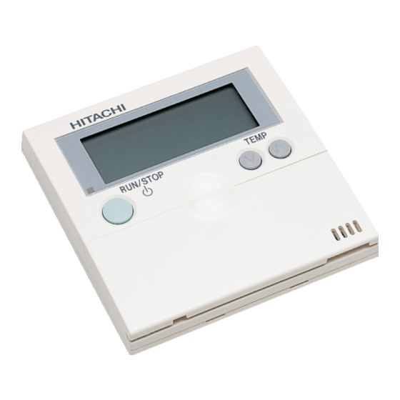
PC-P1HE
MANUAL DE INSTALAÇÄO E DE
FUNCIONAMENTO
BRUGER- OG MONTERINGSVEJLEDNING
INSTALLATIE- EN BEDIENINGSHANDLEIDING
HANDBOK FÖR INSTALLATION OCH ANVÄNDING
ÅÃ×ÅÉÑÉÄÉÏÅÃÊÁÔÁÓÔÁÓÇÓÊÁÉËÅÉÔÏÕÑÃÉÁÓ
Advertisement
Table of Contents

Related Manuals for Hitachi PC-P1HE


Summary of Contents for Hitachi PC-P1HE
- Page 1 PC-P1HE INSTALLATION AND OPERATION MANUAL MANUAL DE INSTALAÇÄO E DE MANUAL DE INSTALACIÓN Y FUNCIONAMIENTO FUNCIONAMENTO INSTALLATIONS- UND BETRIEBSHANDBUCH BRUGER- OG MONTERINGSVEJLEDNING MANUEL D’INSTALLATION ET DE INSTALLATIE- EN BEDIENINGSHANDLEIDING FUNCTIONNEMENT HANDBOK FÖR INSTALLATION OCH ANVÄNDING ÅÃ×ÅÉÑÉÄÉÏÅÃÊÁÔÁÓÔÁÓÇÓÊÁÉËÅÉÔÏÕÑÃÉÁÓ MANUALE D’INSTALLAZIONE E D’USO Read and understand this manual before using this remote controller.
- Page 3 Ö DANGER – Immediate hazard which WILL result in severe injury or death. PELIGRO – Peligros inmediatos que DARÁN como resultado graves lesiones o incluso la muerte. GEFAHR – Ernsthafte Gefahrenquelle, die zu schweren Verletzungen oder zum Tod führt. DANGER – Dangers instantanés de blessures personnelles sévères ou de mort. PERICOLO –...
- Page 4 INDEX ÍNDICE PART I – OPERATION 1ª PARTE – FUNCIONAMIENTO 1. SAFETY SUMMARY 1. RESUMEN DE SEGURIDAD 2. INSTALLATION WORK 2. INSTALACIÓN 3. ELECTRICAL WIRING 3. CABLEADO ELÉCTRICO 4. CHECKING PROCEDURES 4. PROCEDIMIENTOS DE COMPROBACIÓN 5. OPTIONAL SETTING AND 5. AJUSTE OPCIONAL Y AJUSTE DE INPUT/OTPUT SETTING ENTRADA/SALIDA DE LA UNIDAD OF INDOOR UNIT...
- Page 5 - In case that the protective devices often function or the operation switches do not function well, turn OFF the main power supply and contact your service contractor of HITACHI. - In case that other abnormalities are found, stop the system, turn OFF the main power supply and contact your service contractor of HITACHI.
- Page 6 INSTALLATION WORK CAUTION: - DO NOT use the multi-core wire for electrical wiring. If used, some signals of one system transfer to the other system, the signals interfere each other and it cause the malfunction. - DO NOT use thin shield wire such as CPEVS. Such wires with big electrostatic capacity make the transmission signal dull end the transmission error may occurs in case of long distance wiring.
- Page 7 INSTALLATION WORK 2.2. BEFORE INSTALLATION Check the contents and the number of the accessories in the packing. 2 screws M4x16L Remote Control 1 Band. For fixing the Switch, for Operation For fixing Ring Core. Holding Bracket onto Control Cable to Ring Core the wall 2.3.
- Page 8 INSTALLATION WORK 2. Attach the controller to the holding bracket as follows. In case of exposing Remote Control Cable. 1. Fix the holding bracket onto the wall as shown below Fix the holding bracket with the mark "↑UP" upward Screw (Accessory) 2.
- Page 9 INSTALLATION WORK When Using Switch Box. .Peel the insulation at the end of the cable Run the cable into Field-Supplied JIS Box and clamp the M3 solderless terminals (JIS 8336 - 1998) The following 5 types are available. 1. Switch Box for 1 Controller (without Cover) REMOCON...
- Page 10 ELECTRICAL WIRING ELECTRICAL WIRING 3.1. STANDARD WIRING Band Ring core ATTENTION: - Attach the ring core (black) (accessory) when installing the unit. Controller - Insert the controller cable into the ring cable core 2 turns as shown in the right figure before connecting to the terminal board.
- Page 11 ELECTRICAL WIRING Comunication cable shall be Field Supplied. It should be used twist pair Solderless terminal Twist Pair cable: (2 x 0,75mm²) cable 2 x 0,75 mm (the (X Type 1.25-3X) max. total length is 500 m). (Remote Control Switch side) (Terminal Board side) Solderless terminal It can be also used standard...
- Page 12 CHECKING PROCEDURES CAUTION: - In the case that multiple indoor units are controlled simultaneously, set the refrigerant cycle number and the address of Indoor units as indicated below. Address of Indoor Units: Main unit unit unit unit unit unit unit unit unit unit...
- Page 13 OPTIONAL SETTING AND INPUT/OUTPUT SETTING OF INDOOR UNIT OPTIONAL SETTING AND INPUT/OUTPUT SETTING OF INDOOR UNIT 5.1. OPTIONAL SETTING MODE Normal Mode (When unit is not operating) Change to the optional setting mode. Press the “CHECK” switch and the ”RESET” switch simultaneously more than 3 seconds.
- Page 14 OPTIONAL SETTING AND INPUT/OUTPUT SETTING OF INDOOR UNIT 5.3. CHANGING OF OPTIONAL FUNCTIONS AND SETTING CONDITIONS 5.3.1. OPTIONAL SETTING ITEMS Optional Setting Mode (Mode Number “01”) Selection of Optional Setting Items Item Code of Optional HIGH Setting COOL Select the item code SERVI C E by pressing the “TIME”...
- Page 15 OPTIONAL SETTING AND INPUT/OUTPUT SETTING OF INDOOR UNIT Optional Setting Items (cont.) Individual Setting (B) Setting Items Availability *5) Conditions Code Cancel of 3 Minutes 00: Standard Compressor OFF 01: Cancel Guard Remote Control 00: Not Available Thermostat 01, 02: *2) Not Prepared ―...
- Page 16 OPTIONAL SETTING AND INPUT/OUTPUT SETTING OF INDOOR UNIT 5.3.2. INPUT/OUTPUT NUMBER Input/Output Setting Mode (Mode Number “02”) Selection of Input/Output Number Input/Output Number HIGH COOL Select the input/output SERViCE number by pressing the “TIME” switch. HIGH <Example> When selecting 01 (Output 1) COOL SERViCE Input and Output Setting Mode and Connector...
- Page 18 PMML0049 A-08/03 Printed in China...
Need help?
Do you have a question about the PC-P1HE and is the answer not in the manual?
Questions and answers