Grandstream Networks GDS3710 User Manual
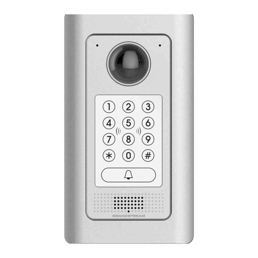
Hemispheric hd ip video door system
Hide thumbs
Also See for GDS3710:
- User manual (133 pages) ,
- Quick installation manual (47 pages) ,
- Connection manual (22 pages)

Related Manuals for Grandstream Networks GDS3710


Summary of Contents for Grandstream Networks GDS3710
- Page 1 Grandstream Networks, Inc. GDS3710 - Hemispheric HD IP Video Door System User Manual...
- Page 2 Grandstream Networks, Inc. is not permitted. The latest electronic version of this user manual is available for download here: http://www.grandstream.com/support Grandstream is a registered trademark and Grandstream logo is trademark of Grandstream Networks, Inc. in the United States, Europe and other countries. CAUTION Changes or modifications to this product not expressly approved by Grandstream, or operation of this product in any way other than as detailed by this User Manual, could void your manufacturer warranty.
- Page 3 GNU GPL INFORMATION GDS3710 firmware contains third-party software licensed under the GNU General Public License (GPL). Grandstream uses software under the specific terms of the GPL. Please see the GNU General Public License (GPL) for the exact terms and conditions of the license.
-
Page 4: Table Of Contents
Power the unit using PoE ......................21 Power the unit using PSU ......................22 GETTING TO KNOW GDS3710 ................... 23 Connecting GDS3710 to Network with DHCP Server ................. 23 Windows Platform ......................... 23 UPnP ..............................23 GS Search ............................. 25 GDS Manager Utility Tool ........................ - Page 5 Connection Examples .......................... 35 Wiring Sample using 3 Party Power Supply ................36 Wiring Sample using Power Supply for both GDS3710 and Electric Strike ......... 36 Wiring Sample using PoE to power GDS3710 and 3 Party Power Supply for Electric Strike ..37 Good Wiring Sample for Electric Strike and High Power Device ..........
- Page 6 Email Settings ..........................68 FTP & Center Storage ........................70 Maintenance Settings .......................... 70 Upgrade ............................71 Reboot & Reset ..........................71 Debug Log ............................ 72 Data Maintenance ......................... 73 Status ..............................74 P a g e GDS3710 User Manual...
- Page 7 System Info ........................... 74 Network Info ..........................75 CONNECTING GDS3710 WITH GXV32XX ..............77 CONNECTING GS WAVE WITH GDS3710 DOOR SYSTEM........78 EXPERIENCING THE GDS3710 .................. 79 P a g e GDS3710 User Manual...
- Page 8 Table of Tables Table 1: GDS3710 Features in a Glance ....................14 Table 2: GDS3710 Technical Specifications ....................14 Table 3: Equipment Packaging ........................17 Table 4: GDS3710 Wiring Connection ......................19 Table 5: Home Page Description ........................ 41 Table 6: Door System Settings ........................45 Table 7: Card Info ............................
- Page 9 Figure 27: Wiegand Input Example with 3 party Power Supply ..............38 Figure 28: Wiegand Input Example with Power Supply for GDS3710 and Wiegand Device ..... 39 Figure 29: Wiegand Output Wiring Example....................39 Figure 30: Wiegand RFID Card Reader Example ..................40 Figure 31: Home Page ..........................
- Page 10 Figure 59: Reset & Reboot Page ........................ 72 Figure 60: Debug Log Page ........................73 Figure 61: Data Maintenance Page ......................74 Figure 62: System Info Page........................75 Figure 63: Network Info Page ........................76 P a g e GDS3710 User Manual...
-
Page 11: Document Purpose
DOCUMENT PURPOSE This document describes the basic concept and tasks necessary to use and configure your GDS3710. And it covers the topic of connecting and configuring the GDS3710, making basic operations and the call features. Please visit http://www.grandstream.com/support to download the latest “GDS3710 User Manual”. -
Page 12: Change Log
CHANGE LOG This section documents significant changes from previous versions of user guide for GDS3710. Only major new features or major document updates are listed here. Minor updates for corrections or editing are not documented here. Firmware Version 1.0.2.9 •... -
Page 13: Welcome
IP based powerful video door system. GDS3710 HD IP Video Door System is a hemispheric IP video door phone and a high-definition IP surveillance camera. GDS3710 is ideal for monitoring from wall to wall without blind spots. Powered by an advanced Image Sensor Processor (ISP) and state of the art image algorithms, it delivers exceptional performance in all lighting conditions. -
Page 14: Product Overview
PRODUCT OVERVIEW Feature Highlights The following table contains the major features of the GDS3710. Table 1: GDS3710 Features in a Glance • High-performance streaming server allowing multiple simultaneous streaming session accesses. • 2 Megapixel Progressive Scan CMOS, 1920H x 1080V. - Page 15 Weather proof, vandal resistant, with support for extra back reinforcing metal plate Operation: -30°C to 60°C (-22°F to 140°F) Temperature and Storage: -35°C to 60°C (-31°F to 140°F) Humidity Humidity: 10% to 90% Non-condensing Protection Class IP66 (EN60529), IK09 (IEC62262) P a g e GDS3710 User Manual...
- Page 16 FCC: Part 15 subpart B Class B; Part 15 C; MPE CE: EN 55032 Class B; EN 61000-3-2; EN 61000-3-3; EN 50130; EN 60950-1; EN 300330; EN 301489; EN 62311 Compliance RCM: AS/NZS CISPR 22; AS/NZS 4268; AS/NZS 60950.1 IC: ICES-003; RSS310 P a g e GDS3710 User Manual...
-
Page 17: Getting Started
GETTING STARTED This chapter provides basic installation instructions including the list of the packaging contents and information for obtaining the best performance using the GDS3710 Video Door System. Equipment Packaging Table 3: Equipment Packaging • • 1 x GDS3710 1 x Wiegand Cable •... -
Page 18: Description Of The Gds3710
Description of the GDS3710 Below figures show the component of the back and front view of GDS3710 IP Video Door System: Figure 2: GDS3710 Front View Figure 3: GDS3710 Back View Connecting and Setting up the GDS3710 The GDS3710 can be powered using PoE or PSU: Using PoE as power supply (Suggested) •... -
Page 19: Gds3710 Wiring Connection
J4 (Special) Black Both Input and Output MUST be connected 2.0mm WG_D1_OUT Orange Wiegand Output GDS3710 function as Output of Card Reader, Connect Signal Pin 1, 2, 3 WG_D0_OUT Brown Wiegand Output For External Card Reader; Or GDS3710 as Receiver... -
Page 20: Gds3710 Back Cover Connections
For External Card Reader Only. Wiegand Power 12VDC powered External Card Reader must use own Output power source, can NOT use this Pin. GDS3710 Back Cover Connections Figure 4: GDS3710 Back Cover Connections P a g e GDS3710 User Manual... -
Page 21: Connection Example
Use the TIA/EIA 568-B standard, which define pin-outs for using Unshielded Twisted Pair cable and RJ-45 connectors for Ethernet connectivity. Figure 6: Connection Example • Connect each wire of the RJ45 to its associate on the Back Cover of the GDS3710 to power the unit using PoE. P a g e GDS3710 User Manual... -
Page 22: Power The Unit Using Psu
GND to negative pole and 12V to positive pole of the PSU. Note: If the user doesn’t have PoE switch, there is no need to connect the Blue and Brown wires to the GDS3710 since these wires are used to power the unit via Ethernet. Figure 7: Powering the GDS3710... -
Page 23: Getting To Know Gds3710
➢ Please trust and install the file downloaded if prompted by the Antivirus or Security software. Connecting GDS3710 to Network with DHCP Server The GDS3710 by default has a DHCP client enabled, it will automatically get IP address from the network running DHCP server. -
Page 24: Figure 8: Detecting Gds3710 Via Upnp
Figure 8: Detecting GDS3710 via UPnP Click on the displayed icon of related GDS3710, the default browser (e.g.: Firefox or Chrome) will open and connect directly to the login webpage. Figure 9: GDS3710 Login Page Once logged in, the prompt message will display asking for plug-in installation. -
Page 25: Gs Search
Double click on a device to access its webGUI. GDS Manager Utility Tool User can know the IP address assigned to the GDS3710 from DHCP server log or using the Grandstream GDS Manager after installing this free utility tool provided by Grandstream. User can find instructions below, for using “GDS Manager”... -
Page 26: Apple Platform
4. The detected devices will appear in the output field like below: Figure 11: GDS3710 Detection 5. Double click the column of the detected GDS3710, the browser will automatically open and show the device’s web configuration page. 6. The browser will ask for plug-in if not installed, please authorize the installation of the plug-in. -
Page 27: Figure 12: Apple Safari Settings Page
Figure 13: Bonjour Setting Page 4. Click on the displayed GDS3710 to access to the configuration page of the GDS3710. 5. To see the video, user should change the video codec from default H.264 to MJPEG, and type in the following on URL: http://IP_Address_GDS3710:Port/mjpeg/mjpegX.html... -
Page 28: Connect To The Gds3710 Using Static Ip
Connect to the GDS3710 using Static IP If there is no DHCP server in the network, or the GDS3710 does not get IP from DHCP server, user can connect the GDS3710 to a computer directly, using static IP to configure the GDS3710. -
Page 29: Figure 15: Static Ip On Windows
Access the Web Configuration Interface. IE will indicate that “This website wants to install the following add-on: GSViewerX.cab from Grandstream Networks Inc.”, allow the installation. Firefox, Chrome users need to download and install the plug-in to see the video from the GDS3710 webGUI. -
Page 30: Gds3710 Application Scenarios
GXV3240 or GXV3275 Video Phones • PoE Switch with related Cat5e/Cat6 wiring • Electronic Lock If remote access to the GDS3710 is required for viewing live video stream, Internet access is required and more equipment such as: • Router. •... -
Page 31: Using A Network Video Recorder (Gvr355X)
Figure 16: Peering GDS3710 with UCM6XXX Using a Network Video Recorder (GVR355X) For implementation with more than two GDS3710s, if local video recording is required to store the record, then an NVR like GXV355X will be added to save all the video stream when people enter the door. -
Page 32: Figure 17: Peering Gds3710 With Gvr3550
Figure 17: Peering GDS3710 with GVR3550 P a g e GDS3710 User Manual... -
Page 33: Gds3710 Peripheral Connections
GDS3710 PERIPHERAL CONNECTIONS Below is the illustration of GDS3710 peripheral connections for related applications. Figure 18: Peripheral Connections for GDS3710 P a g e GDS3710 User Manual... -
Page 34: Alarm In/Out
Higher voltage and wrong polarity connection are prohibited because this will damage the devices. Protection Diode When connecting the GDS3710 to a door strike it is recommended to set an EMF protection diode in reverse polarity for a secure use, below examples of deployment for the protection diode. -
Page 35: Connection Examples
Figure 21: Protection Diode - Example 2 Connection Examples Below examples, show how to use wiring on the back cover of the GDS3710 to connect with external devices. The “NO” (Normal Open) model strike is used as example, “NC” (Normal Closed) should be similar and users need to decide which model (NO or NC) to be used on the door. -
Page 36: Wiring Sample Using 3 Rd Party Power Supply
Party Power Supply Figure 22: 3 party Power Supply Wiring Sample Wiring Sample using Power Supply for both GDS3710 and Electric Strike Figure 23: Power Supply used for both GDS3710 and Electric Strike P a g e GDS3710 User Manual... -
Page 37: Wiring Sample Using Poe To Power Gds3710 And 3 Rd Party Power Supply For Electric Strike
Wiring Sample using PoE to power GDS3710 and 3 Party Power Supply for Electric Strike Figure 24: Wiring Sample using PoE to power GDS3710 and 3 party Power Supply for Electric Strike Warning: The following example should be avoided when powering the electric strike. -
Page 38: Good Wiring Sample For Electric Strike And High Power Device
Figure 26: Electric Strike and High Power Device Example Wiegand Module Wiring Examples GDS3710 package is shipped with one Wiegand cable for Input/Output Wiegand connections, the following examples shows how to connect the Wiegand Input/Output devices to the GDS3710. Input example with 3rd party power supply for Wiegand device... -
Page 39: Input Example With Power Supply For Both Gds3710 And Wiegand Device
If power source is 12VDC, Wiegand device can share same power source of GDS3710. However, users need to check the max power consumption and the max capability of the power source. If Wiegand device is using 5VDC, GDS3710 Wiegand port can provide 5VDC with max 500mA to power up Wiegand device. -
Page 40: Wiegand Rfid Card Reader Example
When the Wiegand output of the GDS3710 is connected, it acts as the signal receiver of the 3 party Wiegand device, connecting to door controller. The major wiring is GND, D0, and D1. Because usually the door controller will consume big current and power, the power supply should be separated. -
Page 41: Gds3710 Home Web Page
GDS3710 HOME WEB PAGE Once logged in successfully to the GDS3710, user will see the following page. 13 14 16 17 18 Figure 31: Home Page Table 5: Home Page Description Number Fields Description LiveView Access to live view stream page. -
Page 42: Gds3710 Configuration & Language Page
Select the webpage language. GDS3710 Configuration & Language Page • Once the IP address of the GDS3710 is entered on the user browser, the login web page will pop up allowing user to configure the GDS3710 parameters. • When clicking on the “Language” drop down, supported languages will be displayed as shown in Figure below. -
Page 43: Gds3710 Settings
GDS3710 SETTINGS Live View Page This page allows users to view the live video of the GDS3710 after installing related plug-in and allowing it to run on from the used browser. Figure 33: Live View Page Three streams are available: •... -
Page 44: Door System Settings
Door System Settings This page allows users to configure parameters regarding system operations, like input PIN for the door and manage users’ settings. Basic Settings Figure 34: Door System Settings Page P a g e GDS3710 User Manual... -
Page 45: Table 6: Door System Settings
Bell Pressed port number (peering mode), to be called when the Door Bell is pressed. Configures PIN code stored in the GDS3710, remote SIP phone needs to Remote PIN to Open the input and match this PIN (the PIN is sent via DTMF while in call) so that Door the GDS3710 can open the door. - Page 46 PIN to open the door using the following sequence [Swipe the card + *Local PIN to Open the Door#] Configures PIN stored in GDS3710, input locally this PIN on the GDS3710 keypad will unlock the door. (This feature needs Private Card PIN: Means every member has a private PIN, the GDS will record who unlocked the door every time.
-
Page 47: Card Management
GDS3710 support RFID for multiple users to open door, therefore every user has its own PIN. For environment with 100 users and more, it’s difficult for the GDS3710 to manage all these users and a separate PC or Server should be involved for such kind of management and monitoring. -
Page 48: Table 7: Card Info
Virtual number is typed followed by # key, the Sip Number will be dialed. Configures the SIP Number is mapped with virtual number, once the virtual SIP Number number is dialed the GDS3710 will send an INVITE to the SIP Number. Cellphone Configures cellphone of the user. Enable Enable/Disable the RFID card. -
Page 49: Add Users Automatically
If [Enable Card Issuing Mode] is checked, the GDS3710 keypad will start blinking and once an RFID card is swiped, data stored on the card will be added into the GDS3710 card management page, user can still edit the entry added automatically by modifying some fields. -
Page 50: Network Settings
Update Interval Configures the Interval (in minutes) to retrieve updates from the NTP server. Network Settings This page allows users to set either a static or DHCP IP address to access the GDS3710. P a g e GDS3710 User Manual... -
Page 51: Table 9: Basic Settings
For example, of the HTTP port is changed to 8088, the RTSP port should be 10088, both TCP ports 8088 and 10088 should be configured for port forwarding to have remote GDS3710 access: 8088 for web portal, and 10088 for video streaming. -
Page 52: Access Settings
Specifies the TCP port for Web Access, default 443. RTSP Port Specifies RTSP port for media stream, default TCP port 554. If no action is made within this time the GDS3710 will logout from the Web User Login Timeout(min) GUI, range is between 3 and 60. -
Page 53: Sip Settings
Displays the SIP registration status. Display “Online” or “Offline”. Account Name Configures the SIP account name used for identification. Configures the FQDN or IP of the SIP server from VoIP service provider SIP Server or local IPPBX. P a g e GDS3710 User Manual... -
Page 54: Sip Advanced Settings
Select “User=Phone” or “Enabled” from the dropdown list. Authenticate Password Sets the Authenticate password used by SIP proxy. SIP Advanced Settings This page allows Advanced SIP parameters to be configured. Figure 42: SIP Advanced Settings Page P a g e GDS3710 User Manual... -
Page 55: White List
This page allows users to configure the white list, which is a phone number or extension list that can call the GDS3710. (the call will be automatically answered when calling from a phone set on the white list). P a g e... -
Page 56: Video & Audio Settings
Deletes a number from the white list. Video & Audio Settings The audio and videos settings allow users to configure the video / audio codecs, videos resolution, CMOS settings and audio related settings. Video Settings P a g e GDS3710 User Manual... -
Page 57: Figure 44: Video Settings Page
Figure 44: Video Settings Page P a g e GDS3710 User Manual... -
Page 58: Table 15: Video Settings
Selects the image quality used when Variable Bit Rate used. I-frame Interval Configures the I-frame interval (suggested 2~3 times of frame rate). Notes: • H.264 suggested if the GDS3710 needs to be viewed via Internet. P a g e GDS3710 User Manual... -
Page 59: Osd Settings
OSD Time Format OSD Time format, choose based on user preference. OSD Text Input a text (to identify the GDS3710) it will be shown on the screen. OSD Date/Time Position Show the Date/Time position on the screen. OSD Text Position Show the text position on the screen. -
Page 60: Audio Settings
Defines how much time the shutter of the camera or exposed to the light, when taking a screenshot. Audio Settings This page allows users to configure the audio settings. Figure 47: Audio Settings Page P a g e GDS3710 User Manual... -
Page 61: Alarm Config
Adjusts the doorbell volume. Alarm Config This page allows users to configure alarm schedule and alarm actions. Alarm Events Config This page allows users to configure GDS3710 events to trigger programmed actions within predefined schedule. P a g e GDS3710 User Manual... -
Page 62: Figure 48: Events Page
Figure 48: Events Page Alarm can be triggered either by motion detection or by GDS3710 input. P a g e GDS3710 User Manual... -
Page 63: Motion Detection
Selects a zone on the screen then click on “Clear” to delete the region. Sensitivity Specifies the region sensitivity (value between 0-100%). Select Alarm Schedule Selects the alarm schedule. Select Alarm Action Profile Selects the programmed Alarm Action profile. P a g e GDS3710 User Manual... -
Page 64: Digital Input 1
Configures the password for the hostage mode. Select Alarm Action Profile Select the Alarm action to be taken when the hostage password is typed on the GDS3710 keypad. Note: No sound alarm will be triggered in this mode. P a g e... -
Page 65: Tamper Alarm
Tamper Alarm Tamper alarm is anti-hack from Hardware level. When this option is checked, if the GDS3710 is removed from the installation board, it will generate the alarm actions configured. There is an embedded mechanism on the GDS3710 that allow it to sense when the it is removed. -
Page 66: Alarm Action
GDS3710 supports up to 10 alarm schedules to be configured, with time span specified by users. User can edit the alarm schedule by clicking button. Usually the 24 hours’ span is 00:00 ~ 23:59, which is 24 hours’ format. Users can copy the configuration to different date during the schedule programming. -
Page 67: Table 24: Alarm Actions
SIP call to pre-configured number. Send Email When checked, an email will be sent when the events are triggered to the pre-configured email account. Sound Alarm When selected, alarm will be played from the GDS3710 Built-in Speaker. P a g e GDS3710 User Manual... -
Page 68: Alarm Phone List
Once the event is triggered (Motion Detection, Door Bell Pressed…), the GDS3710 will call the first number, once time out is reached and no answer is returned from the first number, the GDS3710 will try the next number on the list and so on. Once the remote phone answers the call, an alarm will be played to notify users that an event is triggered. -
Page 69: Table 26: Email Settings - Smtp
Click “Save” to save the email configuration information. • Click “Email Test” after configuration, if settings are correct, a test email will send out and “E-mail test successfully” message on the top page will appear P a g e GDS3710 User Manual... -
Page 70: Ftp & Center Storage
Note: If the connection to the FTP server is successful, a “.txt” file containing a success message will be uploaded to the FTP server. And the following message will pop up on the webGUI Maintenance Settings This page shows the GDS3710 Maintenance parameters. P a g e GDS3710 User Manual... -
Page 71: Upgrade
Activates DHCP option 66 to override upgrade/config servers. Server Zero Config Enables Zero Config feature for auto provisioning. Automatic Upgrade Enables automatic upgrade and provisioning. Reboot & Reset This page allows user to reboot and reset the GDS3710. P a g e GDS3710 User Manual... -
Page 72: Debug Log
Reset There are two options for the reset function. Clear All Data All data will be reset, GDS3710 will be set to factory default. Retain Network Data Only All data will be erased except for Network data like IP address…... -
Page 73: Data Maintenance
• Five levels of Debugging are available, None, Debug, Info, Warning, Error. • Once the Syslog Server and the level entered, press “Save” and then Reboot the GDS3710 to apply the settings. Data Maintenance This page allows user to save the GDS3710 configuration file. -
Page 74: Status
Figure 61: Data Maintenance Page Click on to save the GDS3710 configuration in a predefined directory. Status This page displays GDS3710 system and network information. System Info This page displays information such as the product model, the hardware version, firmware…... -
Page 75: Network Info
RootFS Version Displays the RootFS Version. Prog Version Displays the Prog Version. System Up Time Since Displays the time since the first boot of the GDS3710. Notes: • When the SIP account is registered, the status display will be Online •... -
Page 76: Table 31: Network Info
MAC Address Displays the GDS3710 MAC Address. IP Address Mode Displays the IP address mode used. IP Address Displays the IP address of the GDS3710. Subnet Mask Displays the Subnet Mask used. Gateway Displays the GDS3710 Gateway. DNS Server 1 Displays the Preferred DNS Server. -
Page 77: Connecting Gds3710 With Gxv32Xx
CONNECTING GDS3710 WITH GXV32XX The GDS3710 Door System offers a powerful integration with GXV32xx and allows users to open the door, initiates call to the GDS3710 and gets real time audio/video stream. The GXV3275 can be connected with the GDS3710 in two different ways, either using peering mode (without a SIP server) or through a SIP server. -
Page 78: Connecting Gs Wave With Gds3710 Door System
CONNECTING GS WAVE WITH GDS3710 DOOR SYSTEM The GDS3710 Door System can interact with the GS Wave softphone application to allow users to open door, initiate call to the GDS3710, offering more mobility during security monitoring and increasing connectivity to essential communications and real-time audio/video stream. -
Page 79: Experiencing The Gds3710
EXPERIENCING THE GDS3710 Please visit our website: http://www.grandstream.com to receive the most up-to-date updates on firmware releases, additional features, FAQs, documentation and news on new products. We encourage you to browse our product related documentation, FAQs and User and Developer Forum answers to your general questions.
Need help?
Do you have a question about the GDS3710 and is the answer not in the manual?
Questions and answers