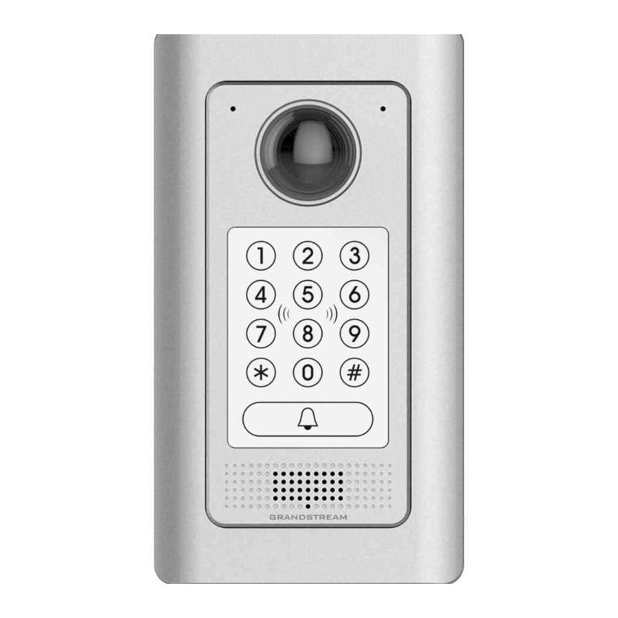
Grandstream Networks GDS3710 Quick Reference Manual
In-wall mounting kit
Hide thumbs
Also See for GDS3710:
- User manual (133 pages) ,
- Quick installation manual (47 pages) ,
- Connection manual (22 pages)
Advertisement
Quick Links
Grandstream Networks, Inc.
126 Brookline Ave, 3rd Floor
Boston, MA 02215. USA
Tel : +1 (617) 566 - 9300
Fax: +1 (617) 249 - 1987
In-Wall Mounting Kit
www.grandstream.com
Quick Reference Guide
For Warranty and RMA information, please visit
(GDS3710/3705 NOT Included)
www.grandstream.com
Advertisement

Summary of Contents for Grandstream Networks GDS3710
- Page 1 126 Brookline Ave, 3rd Floor Boston, MA 02215. USA Tel : +1 (617) 566 - 9300 Fax: +1 (617) 249 - 1987 In-Wall Mounting Kit www.grandstream.com Quick Reference Guide For Warranty and RMA information, please visit (GDS3710/3705 NOT Included) www.grandstream.com...
- Page 2 Content English............1...
- Page 3 Avoid using the device in very low or high temperature environment. • Recommend to seal the frame or wall gap with silicone or This guide applies to both GDS3705 and GDS3710, other sealant after installation to avoid inside water leaking. • Remove the electrostatic adsorption protective plastic film with GDS3710 in the illustration.
-
Page 4: Package Contents
1 x Drill Template on Meta Frame) Box into Solid Wall) into Plastic Box) In-Wall Mounti ng Kit Quick Referenc e Guide (GDS3710 NOT Included PM3*12mm 6 x Nuts 6 x Nuts 6 x Anti-Tamper 1 x Anti-Tamper Metal Frame... -
Page 5: Solid Wall Installation
Solid Wall Installation Please follow below steps to install the device into solid wall. Step 2: Mount the Installation Bracket into the Plastic Box Step 1: Use provided Drill Template to mark boundary then using supplied Screws(2). drill holes for the 6 mounting screws and the circular hole for wiring. - Page 6 Step 4: Step 6: Remove the frame back cover (designed for Surface/ Align the GDS37XX with the bracket, press and push OnWall Installation). down the GDS37XX into place. Step 5: Step 7: Follow GDS37XX QIG and User Manual to connect Install the Cover Plate and fix it using the Hex Key wires to the PoE switch or PoE Injector.
- Page 7 Stud Installation Step 3: Please follow below steps to install the device at the stud of Mount the Installation Bracket into the Plastic Box a new building open wall,or a finished wall. using supplied Screws(2). Step 1: For finished wall, use provided Drill Template to mark boundary and dig a rectangle hole into the wall.
- Page 8 Step 5: Step 7: Remove the frame back cover (designed for Surface/ Align the GDS37XX with the bracket, press and push OnWall Installation). down the GDS37XX into place. Step 6: Step 8: Follow GDS37XX QIG and User Manual to connect Install the Cover Plate and fix it using the Hex Key wires to the PoE switch or PoE Injector.
- Page 9 Drywall (Hollow Wall) Installation Step 3: Insert the Plastic Box into the cutted hole properly. Please follow below steps to install the device on a drywall or hollow wall. The thickness of the wall where the clamps can handle is among 6.2 ~ 24 mm (or 0.24 ~ 0.94 inch) Step 1: Use provided Drill Template to mark boundary then cut opening on the dry wall.
- Page 10 Step 5: Step 7: Remove the frame back cover (designed for Surface/ Align the GDS37XX with the bracket, press and push OnWall Installation). down the GDS37XX into place. Step 6: Step 8: Follow GDS37XX QIG and User Manual to connect Install the Cover Plate and fix it using the Hex Key wires to the PoE switch or PoE Injector.


Need help?
Do you have a question about the GDS3710 and is the answer not in the manual?
Questions and answers