Table of Contents
Advertisement
Quick Links
1 • PRELIMINARY INSTRUCTIONS ....................................2
1.1 Profile ........................................................................ 2
1.2 General Description .................................................. 2
1.3 Preliminary instructions ............................................. 3
2 • INSTALLATION AND CONNECTION ............................4
2.1 Electrical power supply ............................................. 4
compatibility: ............................................................ 4
of EMC ...................................................................... 4
2.4 Dimensions ............................................................... 7
2.5 Template dimensions ................................................ 8
2.6 Installation ................................................................. 8
2.7 Short circuit protection .............................................. 9
2.8 General description GFW ........................................ 10
2.9 Cleaning/checking or replacing the fan .................... 11
2.10 Replacing the internal fuse (Optional) ..................... 12
2.11 Card insertion for fieldbus interface ......................... 13
3 • ELECTRICAL CONNECTIONS ......................................14
3.1 Power connections .................................................. 14
3.2 Functions of leds indicators ..................................... 16
To differentiate the type and importance of the information in this User Manual, graphic reference symbols are used to make such information easier
to interpret.
Indicates contents of sections, general instructions, notes,
and other points to which the reader's attention needs to be
called.
Indicates a particularly delicate situation that could affect
the safety or correct operation of the controller, or an
instruction that MUST be followed to prevent hazards.
Indicates a risk to the user's safety due to high voltage at the
points indicated.
80999D_MHW_GFW 400-600A_07-2020_ENG
GFW 400-500-600A
MODULAR POWER CONTROLLER
INDEX
GRAPHIC SYMBOLS
INSTALLATION AND
OPERATION MANUAL
Software version: 01:00
code 80999C - 05-2019 - ENG
3.3 Description Input/Output .......................................... 17
3.4 Description of dip-switches ...................................... 23
3.5 Serial communication ports ..................................... 24
3.6 Connection example: Power section ....................... 30
3.8 Trigger modes .......................................................... 38
3.9 Digital input (PWM) .................................................. 42
4.1 "AUTOBAUD SERIAL 1" sequence ......................... 44
5 • TECHNICAL CHARACTERISTICS ................................45
5.1 Derating Curves ....................................................... 49
6 • Commercial Information ................................................50
6.1 Order code ............................................................... 50
6.2 Accessories ............................................................. 51
6.3 Fuses ....................................................................... 52
Indicates a suggestion based on the experience of GEFRAN's
Technical Personnel that could be especially useful under
certain circumstances.
Indicates a reference to Detailed Technical Documents
available on the GEFRAN website www.gefran.com.
1
Advertisement
Table of Contents

Related Manuals for gefran GFW 400A


Summary of Contents for gefran GFW 400A
-
Page 1: Table Of Contents
To differentiate the type and importance of the information in this User Manual, graphic reference symbols are used to make such information easier to interpret. Indicates a suggestion based on the experience of GEFRAN’s Indicates contents of sections, general instructions, notes, Technical Personnel that could be especially useful under and other points to which the reader’s attention needs to be... -
Page 2: Preliminary Instructions
IR lamp flickering), matched with current, voltage, or load power In particular, this new line of Gefran solid state relays is the ideal solution feedback functions, let you confidently use “critical” applications such as for sectors demanding high performance and continuity of service, such (for example), special resistors such as special Super Khantal™... -
Page 3: Preliminary Instructions
See paragraph “ Dimensions and mounting” before installing the GFW on reliminary instructions the machine/host system control panel. To configure the PC use the SW Gefran GF-Express kit and the relative Please read the following preliminary warnings before installing and using your GFW modular power controller. -
Page 4: Installation And Connection
2 • INSTALLATION AND CONNECTION This section contains the instructions needed for correct ecommenDations for orrect nstallation installation of GFW modular power controller on the machine/ for PurPoses of host system control panel and for correct connection of the power supply, inputs, outputs and interfaces. 2.3.1 2.3.1 Instrument power supply •... - Page 5 RC Snubber circuit to protect the thyristor). • dissipation of device thermal power with effects on installation room temperature. GEFRAN S.p.A. assumes no liability for any damage • thermal power dissipation with limits on installation room temperature. to persons or property deriving from tampering, from incorrect or improper use, or from any use not •...
- Page 6 GFW-400/600A INSULATION DIAGRAM 80999D_MHW_GFW 400-600A_07-2020_ENG...
-
Page 7: Dimensions
imensions Figure 1 SINGLE-PHASE GFW GFW DUAL-PHASE GFW THREE-PHASE 80999D_MHW_GFW 400-600A_07-2020_ENG... -
Page 8: Template Dimensions
emPlate Dimensions Figure 2 GFW MASTER GFW BI-PHASE GFW THREE-PHASE 31.5 31.5 31.5 15.8 65.0 65.0 15.8 65.0 65.0 65.0 65.0 65.0 15.8 65.0 65.0 M5(X4 FORI) M5(X8 FORI) M5(X12 FORI) 339.0 339.0 339.0 nstallation Figure 3 Attention: respect minimum distances shown in figure 3 to provide adequate air circulation. -
Page 9: Short Circuit Protection
hort circuit Protection Products listed in table "UL508 SCCR FUSES TABLE " are suitable for use on a circuit capable of delivering not more than 100,000 A rms Symmetrical Amperes, 600 Volts maximum when protected by fuses. Use fuses only According to UL508, test at 100.000A were carried out with class J fuses rated xxxA (refer to table "SCCR fuse protection table"... -
Page 10: General Description Gfw
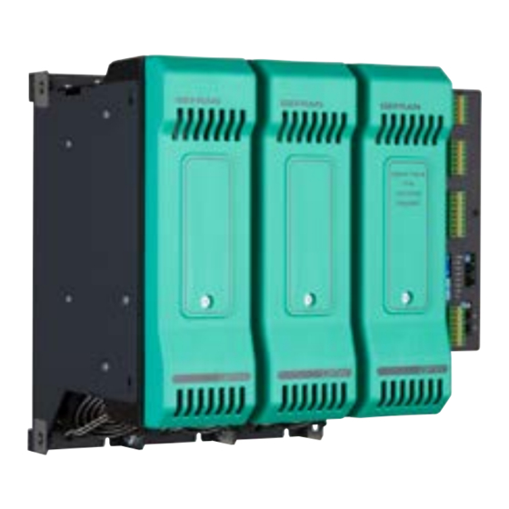
eneral DescriPtion Figure 4 1 Auxiliary output connector 10 Cover on internal fuse protection and Line / Load connections 2 Relay output connector 11 Line terminal (pre-split protection grid) 3 24V digital input connector and power supply 12 V-load measurement connector 4 Dip Switch configuration 13 V-line measurement connector 5 Rotary Switch (address) -
Page 11: Cleaning/Checking Or Replacing The Fan
leaninG checkinG or rePlacinG the fan PERIODIC CLEANING Every 6-12 months (depending on the dust level of the installation) blow a compressed air jet downward through the upper rectangular cooling grilles (on the side opposite the fan). This will clean the internal heat dissipater and the cooling fan. IN CASE OF OVERHEAT ALARM If periodic cleaning does not eliminate the problem, perform the following operations after first checking that the GFW has been turned off and cut off from the electrical power supply to ensure the operator’s safety:... -
Page 12: Replacing The Internal Fuse (Optional)
CAUTION: the washer must be between the bolt and the copper strap (NOT under the fuse). - Tighten the two nuts with a No. 19 spanner (GFW 500/600A) or a No. 17 spanner (GFW 400A), to a torque of 12 Nm. -
Page 13: Card Insertion For Fieldbus Interface
2.11 arD insertion for fielDbus interface DO AS FOLLOWS: a. Slacken the screws (1) on the front piece and remove the front piece (2). b. Slacken the screws (3) on the CPU cover and remove the cover (4). c. Insert the Fieldbus interface card (5) in the connectors provided on the supporting card (6). Check that the card is inserted correctly. -
Page 14: Electrical Connections
3 • ELECTRICAL CONNECTIONS ower connections GFW 400-500-600A RECOMMENDED WIRE GAUGES TYPE CABLE / SECTION TERMINAL TYPE TIGHTENING / Wiring CURRENT TERMINAL TYPE RAIL / SECTION CABLE / RAIL TOOL TORQUE notes LEVEL N. 1 Bolt M12x25mm UNI 5739 Single cable - 300 mm Wire crimped at terminal tube 400A 1/L1, 2/T1... - Page 15 80999D_MHW_GFW 400-600A_07-2020_ENG...
-
Page 16: Functions Of Leds Indicators
unctions of leDs inDicators Table 4 Description of LEDs Description color color Run - flashing during normal operation green Error status: activated in the presence of an alarm State digital input 1 yellow State digital input 2 yellow State output Out 1 yellow State output Out 2, only with GFW 2ph o 3 ph products yellow... -
Page 17: Description Input/Output
escriPtion nPut utPut Figure 10 Top View Bottom View V-Line Ground protection Connector 2/T1 "Load" Output connection Connector 3 inputs 3/L1 4/L2 (DIN or cable) external CT (optional) (Ref. V_Line) TA1+ TA1 - Connector TA2+ for Keypad TA2 - V-Load GFW-OP TA3+ Connector (optional) - Page 18 3.3.1 Connector J1 outputs 5...10 Connector J1 will be assembled in the presence of auxiliary outputs (O5...O8). Figure 11 Connector J1 Table 6 0.25 - 2.5mm2 23-14AWG 0.25 - 2.5mm2 23-14AWG OUTPUTS 5...8 Logical (option D) / Analogue (option W) Logic outputs: 18...36Vdc, max 20mA Continuous outputs: voltage (default) 0/2...10V, max 25mA...
- Page 19 3.3.2 Connector J2 outputs 9, 10 Figure 14 Connector J2 Table 9 0.25 - 2.5mm2 23-14AWG 0.25 - 2.5mm2 23-14AWG RELAY OUTPUTS 9, 10 Outputs Out 9, 10 relay 5A max, Relay with exchange contact (C, NC, NO) V = 250V/30Vdc cosφ = 1; I = 5A max Figure 15 Connection scheme for relay outputs Table 10...
- Page 20 3.3.3 Connector J3 Power supply and digital inputs. Figure 16 Table 11 0.25 - 2.5mm2 23-14AWG 0.25 - 2.5mm2 23-14AWG Table 12 Name Description +24Vdc 24 Vdc supply Earth Earth EMC + INDIG1 Digital input 1 (5 … 32Vdc) configurable NPN / PNP + INDIG2 Digital input 2 (5 …...
- Page 21 3.3.4 Connector J4 ANALOGUE CONTROL INPUTS Figure 18 Table 13 0.25 - 2.5mm2 23-14AWG 0.25 - 2.5mm2 23-14AWG Table 14 Name Description +5V_POT Output 5V potentiometer(s) power supply (max 30 mA) +INA1 Analogue command input INA1 GND command signal EARTH Earth EMC +INA2 Analogue command input INA2...
- Page 22 3.3.5 Connector J5 EXTERNAL TA INPUTS (optional) Figure 20 Connector J5 Table 15 0.25 - 2.5mm2 23-14AWG 0.25 - 2.5mm2 23-14AWG Figure 21 Connection scheme Table 16 Name Description TA1+ External TA1 input (max 5 A rms) TA1- TA2+ External TA2 input (max 5 A rms) TA2- TA3+ External TA3 input (max 5 A rms)
-
Page 23: Description Of Dip-Switches
escriPtion of DiP switches Figure 22 Connector J5 Table 17 dip-switches Decription Connection type: (see table 23) Connection type: (see table 23) Connection type: (see table 23) Connection type: (see table 23) OFF = resistive load ON = inductive load (transformer primary control) ON = reset factory configuration ON = Geflex simulation function Table 18... -
Page 24: Serial Communication Ports
erial communication portS Port1 (local bus): Modbus serial interface – connectors S1, S2. Figure 23 Table 19 Connector J8/J9 Nr. Pin Name Decription Note RJ10 4-4 pin GND1 (**) (*) (*) Insert the RS485 line termination in the last Tx/Rx+ Data reception/transmission (A+) device on the Modbus line, see dipswitches. - Page 25 Port2 (fieldbus): connectors S4, S5 MODBUS RTU/MODBUS RTU Figure 24 Port2: Fieldbus Modbus RTU/Modbus RTU interface Connector S5 Connector S4 Line termination (*) Table 20 Connector S4/S5 Nr. Pin Name Decription Note RJ10 4-4 pin GND1 (**) (*) (*) Insert the line termination in the last device Tx/Rx+ Data reception/transmission (A+) on the Modbus line.
- Page 26 Port2 (fieldbus): connectors S4, S5 MODBUS RTU/Profibus DP Figure 25 Port2: Fieldbus Modbus RTU/Profibus DP interface S5 female connector S4 female connector Yellow Led Red Led Green Led Table 21 Connector S4 Nr. Pin Name Decription Note RJ10 4-4 pin GND1 (**) Tx/Rx+ Data reception/transmission (A+) (**) Connect the GND signal between Modbus...
- Page 27 Port2 (fieldbus): connectors S4, S5 MODBUS RTU/CANOpen Figure 26 Port2: Fieldbus Modbus RTU/CANOpen Interface S5 male connector S4 female connector Red Led Green Led Table 23 Connector S4 Nr. Pin Name Decription Note RJ10 4-4 pin GND1 (**) Tx/Rx+ Data reception/transmission (A+) (**) Connect the GND signal between Modbus devices with a line distance >...
- Page 28 Port2 (fieldbus): connectors S4, S5 Modbus RTU / Ethernet Modbus TCP Figure 27 Port2: Interfaccia Modbus RTU / Ethernet Modbus TCP S5 female connector S4 female connector Table 25 Connector S4 Nr. Pin Name Decription Note RJ10 4-4 pin GND1 (**) Tx/Rx+ Data reception/transmission (A+) (**) Connect the GND signal between Modbus devices with a line distance >...
- Page 29 Port2 (fieldbus): connectors S4, S5 Modbus RTU / Ethernet IP or Modbus RTU / EtherCAT Figure 28 Port2: Modbus RTU / Ethernet IP or Modbus RTU / EtherCAT Green led Packet activity Yellow led Link integrity S4 female connector S5 female connector Table 27 ...
-
Page 30: Connection Example: Power Section
onnection examPle ower section Figure 29 GFW connection example for 1 single-phase load (*) IMPORTANT: Take care to connect terminals 1/L1 and 3/L1 to the same phase (**) Only required with Vload measurement input option. V phase voltage (line - neutral) P power of each single-phase load Id load current if resistive load cosφ=1 FIRING MODE ZC, BF, HSC, PA... - Page 31 Figure 31 Example of GFW-2PH for 2 indipendent single phase loads It is possible to connect two single-phase loads also to different line voltages, between line to line or line to neutral It is possible to manage different power values for each one of the two loads. (*)IMPORTANT: Take care to connect...
- Page 32 Figure 32 Sample GFW biphase connection for a triphase star load without neutral (*) IMPORTANT: Take care to connect terminals 1/L1 and 3/L1 to the same phase (**) Only required with Vload measurement input option. V line voltage P total power Id load current pif resistive load cosφ=1 FIRING MODE ZC, BF HB DIAGNOSTIC...
- Page 33 Figure 34 Sample GFW biphase connection for a triphase closed delta load (*) IMPORTANT: Take care to connect terminals 1/L1 and 3/L1 to the same phase (**) Only required with Vload measurement input option. V line voltage P total power Id load current if resistive load cosφ=1 FIRING MODE ZC, BF HB DIAGNOSTIC...
- Page 34 Figure 36 GFW connection example for 1 3-phase closed delta load (*)IMPORTANT: Take care to connect terminals 1/L1 and 3/L1 to the same phase (**)Only required with Vload measurement input option. V line voltage P total power Id load current if resistive load cosφ=1 FIRING MODE ZC, BF, PA Partial and total load breakage for each HB DIAGNOSTIC...
- Page 35 Figure 38 GFW connection example for 1 3-phase star load without neutral (*)IMPORTANT: Take care to connect terminals 1/L1 and 3/L1 to the same phase (**)Only required with Vload measurement input option. V line voltage Vd tensione del carico P total power Id load current if resistive load cosφ=1 FIRING MODE ZC, BF, PA HB DIAGNOSTIC...
- Page 36 Figure 40 GFW connection example for 1 3-phase star load with neutral (*)IMPORTANT: Take care to connect terminals 1/L1 and 3/L1 to the same phase (**)Only required with Vload measurement input option. V line voltage Vd load voltage P total power Id current in three-phase load if resistive load cosφ...
- Page 37 Figure 42 GFW connection example for 3 independent loads in open delta, 3-phase line without neutral (*)IMPORTANT: Take care to connect terminals 1/L1 and 3/L1 to the same phase (**)Only required with Vload measurement input option. V line voltage P power of each single-phase load Id load current if resistive load cosφ=1 FIRING MODE ZC, BF, HSC, PA HB DIAGNOSTIC...
-
Page 38: Notes: Use With Inductive Loads And Transformers
oteS uSe with inductive loadS and tranSformerS a. When the GFW is working it is not allowed to open neither the connection between GFW and the transformer nor the connection between the transformer and the load b. The maximum current controllable by the device is less than the product’s rated value (see technical data). c. - Page 39 Figure 45 Example of operation in BF mode with power at 50% Parameter defines the minimum number of conduction cycles settable from 1 to 10. In the following example, the parameter = 2. HSC - Half single cycle This mode corresponds to Burst Firing that manages ON and OFF half-cycles. It is useful for reducing the flickering of filaments with short/medium-wave IR lamp loads.
- Page 40 ADDITIONAL FUNCTIONS Softstart This type of start can be enabled either in phase control or pulse train mode and in zero-crossing mode (ZC, BF, HSC). In phase control, the increment of conduction angle q stops at the corresponding value of the power to be transferred to the load. Control of maximum peak current (useful in case of short circuit on the load or of loads with high temperature coefficients to automatically adjust start time to the load) can be enabled during softstart.
- Page 41 DT - “Delay triggering” (for ZC, BF control modes only) Settable from 0° to 90°. Useful for inductive loads (transformer primaries) to prevent current peak that in certain cases could trip the high-speed fuses that protect the SCRs. Figure 50 Transient with Transient without Over-Current...
-
Page 42: Digital Input (Pwm)
The signal can be generated by a controller or external plc via digital outputs (logic output for Gefran instrumentation). This is obtained by alternating the output in ON for time TON with the output in OFF for time TOFF. -
Page 43: Installation Of "Modbus" Serial Network
4 • INSTALLATION OF “MODBUS” SERIAL NETWORK A network typically has a Master that “manages” communication by means of “commands,” and Slaves that carry out these commands. GFW modules is considered Slaves to the network master, which is usually a supervision terminal or a PLC. It is positively identified by means of a node address (ID) set on rotary switches (tens + units). -
Page 44: Autobaud Serial 1" Sequence
“autoBaud Serial 1” Sequence Function Adapt the serial communication speed and parity of the GFW modules to the connected supervision terminal or PLC. Green LED L1 “STATUS” mentioned in the procedure can vary its behavior based on parameter Ld.1, which is set to a default value of 16. -
Page 45: Technical Characteristics
5 • TECHNICAL CHARACTERISTICS INPUTS INA1, INA2, INA3 ANALOGUE CONTROL INPUTS Function Acquisition of % value for power control Linear: 0..5 Vdc, Ri= 90Kohm Voltage Linear: 0..10 Vdc, Ri= 90Kohm Current Linear: 0/4…20mA, Ri =250ohm Potentiometric 1..10 Kohm, max 30mA from 5Vdc power GFW Line Voltage measurement, Current /Voltage (optional) on load Line voltage read 50-60Hz;... - Page 46 OUTPUTS OUT1, …, OUT3 Heating outputs (connected directly to static units) Configurable (default: heat control) State of control is displayed by LED (O1, O2, O3) Function OUT1 is connected to Master unit, OUT2 and OUT3 are connected to Expansion units auxiliary OUT5,...,OUT8 outputs (optional) Function Configurable...
- Page 47 POWER (SOLID-STATE RELAY) AC 51 resistive or low inductance loads CATEGORY OF USE AC 55b short wave infrared lamps (SWIR) (Tab. 2 EN60947-4-3) AC 56a transformers, resistive loads with high temperature coefficient PA - load control via adjustment of firing phase angle ZC - Zero Crossing with constant cycle time (settable in range 1-200sec) BF - Burst Firing with variable cycle time (GTT) optimized min.
- Page 48 FUNCTION - Timed Soft-Start firing ramp, with or without peak current control - Soft-Start firing ramp, specific for infrared lamps Options - Timed shut-off ramp - Limitation of RMS current in load - 0-90° Delay-Triggering for firing inductive loads in ZC and BF mode - SCR in short circuit (presence of current with OFF control) - No linear voltage...
-
Page 49: Derating Curves
Model with GFW-1PH GFW-2PH GFW-3PH internal fuse GFW 400 8 Kg 15.5 Kg 22.5 Kg Weight GFW 500/600 11 Kg 21 Kg 31 Kg GFW-1PH GFW-2PH o GFW-3PH Packaging dimension 420 x 480 x 250 mm 420 x 520 x 510 mm erating urveS Figure 53... -
Page 50: Commercial Information
(****) To check the compatibility between the different product releases please look at the specific technical documentation on the web site www.gefran.com. GEFRAN spa reserves the right to make aesthetic or functional changes at any time and without notice 80999D_MHW_GFW 400-600A_07-2020_ENG... -
Page 51: Accessories
ccessories CONFIGURATION KIT KIT PC USB / RS485 o TTL Configuration/supervision kit for GFW by means of PC with USB (Windows environment). Lets you read or write all of the parameters of a single GFW A single software for all models •... -
Page 52: Fuses
(see EN60439-1, par. 7.5 “Short-circuit protection and short-circuit with stand strength” and 7.6 “Switching devices and components installed in assemblies”, otherwise the equivalent EN61439-1 paragraphs) GEFRAN spa via Sebina, 74 - 25050 Provaglio d’Iseo (BS) Tel. 03098881 - fax 0309839063 - Internet: http://www.gefran.com...
Need help?
Do you have a question about the GFW 400A and is the answer not in the manual?
Questions and answers