Table of Contents
Advertisement
Quick Links
Advertisement
Table of Contents

Related Manuals for Supermicro X12DPFR-AN6


Summary of Contents for Supermicro X12DPFR-AN6
- Page 1 X12DPFR-AN6 USER'S MANUAL Revision 1.0a...
- Page 2 State of California, USA. The State of California, County of Santa Clara shall be the exclusive venue for the resolution of any such disputes. Supermicro's total liability for all claims will not exceed the price paid for the hardware product.
- Page 3 Scalable Processors (in Socket P+) and three UPIs (UltraPath Interconnect) of up to 11.2GT/s. Built with the Intel C621A chipset, the X12DPFR-AN6 supports up to 2TB 3DS LRDIMM/ LRDIMM/3DS RDIMM/RDIMM DDR4 ECC memory with speeds up to 3200 MHz and Intel®...
- Page 4 Super X12DPFR-AN6 User's Manual Contacting Supermicro Headquarters Address: Super Micro Computer, Inc. 980 Rock Ave. San Jose, CA 95131 U.S.A. Tel: +1 (408) 503-8000 Fax: +1 (408) 503-8008 Email: marketing@supermicro.com (General Information) support@supermicro.com (Technical Support) Website: www.supermicro.com Europe Address: Super Micro Computer B.V.
-
Page 5: Table Of Contents
Preface Table of Contents Chapter 1 Introduction 1.1 Important Links ........................7 1.2 Processor and Chipset Overview ..................15 1.3 Special Features ........................16 1.4 System Health Monitoring ....................16 1.5 ACPI Features ........................17 1.6 Power Supply ........................17 ® 1.7 Intel Optane™ Persistent Memory (PMem) 200 Series Overview ........17 Chapter 2 Installation 2.1 Static-Sensitive Devices .....................18 2.2 Processor and Heatsink Installation ...................19... - Page 6 Table of Contents Chapter 3 Troubleshooting 3.1 Troubleshooting Procedures ....................54 3.2 Technical Support Procedures ...................57 3.3 Frequently Asked Questions ....................58 3.4 Battery Removal and Installation ..................59 3.5 Returning Merchandise for Service ..................60 Chapter 4 UEFI BIOS 4.1 Introduction .........................61 4.2 Main Setup .........................62 4.3 Advanced Setup Configurations ..................64 4.4 Event Logs ........................110 4.5 BMC ..........................112...
-
Page 7: Chapter 1 Introduction
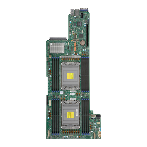
Chapter 1 Introduction Congratulations on purchasing your computer motherboard from an industry leader. Supermicro motherboards are designed to provide you with the highest standards in quality and performance. 1.1 Important Links For your system to work properly, please follow the links below to download all necessary drivers/utilities and the user’s manual for your computer. - Page 8 Super X12DPFR-AN6 User's Manual Figure 1-1. X12DPFR-AN6 Motherboard Image Note: All graphics shown in this manual were based upon the latest PCB revision available at the time of publication of the manual. The motherboard you received may or may not look exactly the same as the graphics shown in this manual.
- Page 9 Chapter 1: Introduction Figure 1-2. X12DPFR-AN6 Motherboard Layout (not drawn to scale) JVGA1 USB0/1 IPMI_LAN (3.0) BIOS BMC FW BATTERY AIOM:CPU1 PCI-E 4.0 X16 JBT1 CMOS CLEAR X12DPFR-AN6 REV:1.01 CPU1 BAR CODE CPU2 JPWR1 JPWR2 Note: Components not documented are for internal testing only.
- Page 10 Super X12DPFR-AN6 User's Manual UID_LED1 BMC_LAN USB0/1 (3,0) JVGA1 COM Port USB0/1 IPMI_LAN (3.0) LEDSYS1 LEDSTBY1 LEDM1 BIOS JIPMB1 CPLD1 JSXB1 JAIOM1 BMC FW BATTERY BATTERY VROC AIOM:CPU1 PCI-E 4.0 X16 S~SATA1 S~SATA0 JBT1 JBT1 CMOS CLEAR HDD_LED1 JTPM1 X12DPFR-AN6 JPWR_HDD1 REV:1.01...
- Page 11 Rear Accessible USB Header with two USB 3.0 connectors (USB0/1) VGA (JVGA1) VGA Port Note: For detailed instructions on how to configure VROC RAID settings, please refer to the VROC RAID Configuration User's Guide posted on the web page under the link: http://www.supermicro.com/manuals/.
- Page 12 Super X12DPFR-AN6 User's Manual Motherboard Features Motherboard Features • Supports the 3rd Gen Intel Xeon Scalable Processors (in Socket P+ LGA 4189) Note: The runtime CPU core counts and maximum CPU TDP (Thermal Design Power) support are dependent on system configurations.
- Page 13 • Power-on mode for AC power recovery • Intel® Intelligent Power Node Manager 3.0 (available when the Supermicro Power Manager [SPM] is installed and a special power supply is used. See the note on page 20.) • Management Engine (ME) System Health Monitoring •...
- Page 14 Super X12DPFR-AN6 User's Manual Figure 1-3. System Block Diagram CPU 1 CPU 2 SKT-P+ SKT-P+ 10.4GT/s or 11.2GT/s P3 P1 P0 P2 DMI3 P0 P1 P2 P3 DMI3 Up to 3200MT/s Up to 3200MT/s PCIe 4.0 X16 PCIe Slot PCIe 4.0 X4 X4 or X8 Gen Z PCIe 4.0 X4 X4 X4 X4...
-
Page 15: Processor And Chipset Overview
1.2 Processor and Chipset Overview Built upon the functionality and capability of the 3rd Gen Intel Xeon Scalable Processors (Socket P+) and the Intel C621A chipset, the X12DPFR-AN6 motherboard provides system performance, energy efficiency, and feature sets optimized for high-performance computing, artificial intelligence (AI), deep learning (DL), big data, and enterprise applications. -
Page 16: Special Features
Super X12DPFR-AN6 User's Manual 1.3 Special Features Recovery from AC Power Loss The Basic I/O System (BIOS) provides a setting that determines how the system will respond when AC power is lost and then restored to the system. You can choose for the system to remain powered off (in which case you must press the power switch to turn it back on), or for it to automatically return to the power-on state. -
Page 17: Acpi Features
It is even more important for processors that have high CPU clock rates where noisy power transmission is present. The X12DPFR-AN6 motherboard has two 8-pin power input connectors (JPWR1/JPWR2) that can be connected a power distribution board (PDB) via a power adaptor to supply power to the motherboard. -
Page 18: Chapter 2 Installation
Super X12DPFR-AN6 User's Manual Chapter 2 Installation 2.1 Static-Sensitive Devices Electrostatic Discharge (ESD) can damage electronic com ponents. To avoid damaging your motherboard, it is important to handle them very carefully. The following measures are generally sufficient to protect your equipment from ESD. -
Page 19: Processor And Heatsink Installation
Thermal grease is pre-applied on a new heatsink. No additional thermal grease is needed. • Refer to the Supermicro website for updates on processor and memory support. • All graphics in this manual are for illustrations only. Your components may look different. - Page 20 Super X12DPFR-AN6 User's Manual 1. The 3rd Gen Intel Xeon Scalable Processor CPU Key Pin 1 = Pin 1 = CPU Key = Cutout Processor Top View...
- Page 21 Chapter 2: Installation 2. The Processor Carrier Carrier Bottom View = Cutout = Pin 1 = CPU Key...
- Page 22 Super X12DPFR-AN6 User's Manual 3. Heatsink Note: Exercise extreme care when handling the heatsink. Pay attention to the edges of heatsink fins which can be sharp! To avoid damaging the heatsink, please do not apply excessive force on the fins when handling the heatsink.
-
Page 23: Overview Of The Cpu Socket
Chapter 2: Installation Overview of the CPU Socket The CPU socket is protected by a plastic protective cover. Plastic Protective Cover CPU Socket... -
Page 24: Overview Of The Processor Carrier Assembly
Super X12DPFR-AN6 User's Manual Overview of the Processor Carrier Assembly The processor carrier assembly contains a 3rd Gen Intel Xeon Scalable processor and a processor carrier. Carefully follow the instructions given in the installation section to place a processor into the carrier to create a processor carrier. -
Page 25: Overview Of The Processor Heatsink Module
Chapter 2: Installation Overview of the Processor Heatsink Module The Processor Heatsink Module (PHM) contains a heatsink, a processor carrier, and a 3rd Gen Intel Xeon Scalable processor. 1. Heatsink (with Thermal Grease) 2. Processor Carrier 3. The 3rd Gen Intel Xeon Scalable Processor Bottom View 4. -
Page 26: Creating The Processor Carrier Assembly
Super X12DPFR-AN6 User's Manual Creating the Processor Carrier Assembly The processor carrier assembly contains a 3rd Gen Intel Xeon Scalable Family processor and a processor carrier. To create the processor carrier assembly, please follow the steps below: Note: Before installation, be sure to follow the instructions given on Page 1 & Page 2 of this chapter to properly prepare yourself for installation. - Page 27 Chapter 2: Installation 3. Locate the lever on the CPU socket and press the lever down as shown below. Lever 4. Using Pin 1 as a guide, carefully align the CPU keys (A & B) on the processor against the CPU keys on the carrier (a & b) as shown in the drawing below. 5.
-
Page 28: Creating The Processor Heatsink Module (Phm)
Super X12DPFR-AN6 User's Manual Creating the Processor Heatsink Module (PHM) After creating the processor carrier assembly, please follow the instructions below to mount the processor carrier into the heatsink to form the processor heatsink module (PHM). Note: If this is a new heatsink, the thermal grease has been pre-applied on the un- derside. -
Page 29: Preparing The Cpu Socket For Installation
Chapter 2: Installation Preparing the CPU Socket for Installation This motherboard comes with a plastic protective cover installed on the CPU socket. Remove it from the socket by following the instructions given in the drawings below. Removing the plastic protective cover from the socket 1. -
Page 30: Preparing To Install The Processor Heatsink Module (Phm) Into The Cpu Socket
Super X12DPFR-AN6 User's Manual Preparing to Install the Processor Heatsink Module (PHM) into the CPU Socket After assembling the Processor Heatsink Module (PHM), you are ready to install it into the CPU socket. To ensure the proper installation, please follow the procedures below: 1. -
Page 31: Installing The Processor Heatsink Module (Phm)
Chapter 2: Installation Installing the Processor Heatsink Module (PHM) 1. Align peek nut "A", which is next to the triangle (Pin 1) on the heatsink, against threaded fastener "a" on the CPU socket. Then align peek nuts "B", "C", "D" on the heatsink against threaded fasteners "b", "c", "d"... -
Page 32: Removing The Processor Heatsink Module From The Cpu Socket
Super X12DPFR-AN6 User's Manual Removing the Processor Heatsink Module from the CPU Socket Before removing the processor heatsink module (PHM) from the motherboard, unplug the AC power cord from all power supplies after shutting down the system. Then follow the steps below: 1. - Page 33 Chapter 2: Installation Removing the Processor Carrier Assembly from the Processor Heatsink Module (PHM) To remove the processor carrier assembly from the PHM, please follow the steps below: 1. Detach four plastic clips (marked a, b, c, d) on the processor carrier assembly from the four corners of heatsink (marked A, B, C, D) in the drawings below.
-
Page 34: Removing The Processor From The Processor Carrier Assembly
Super X12DPFR-AN6 User's Manual Removing the Processor from the Processor Carrier Assembly Once you have removed the processor carrier assembly from the PHM, you are ready to remove the processor from the processor carrier by following the steps below. 1. Unlock the lever from its locking position and push the lever upwards to disengage the processor from the processor carrier as shown in the right drawing below. -
Page 35: Motherboard Installation
(11) Only if Needed BIOS BMC FW BATTERY AIOM:CPU1 PCI-E 4.0 X16 JBT1 CMOS CLEAR X12DPFR-AN6 REV:1.01 CPU1 BAR CODE CPU2 JPWR1 JPWR2 Location of Mounting Holes Note 1: To avoid damaging the motherboard and its components, please do not use a force greater than 8 lbf-in on each mounting screw during motherboard installation. - Page 36 Super X12DPFR-AN6 User's Manual Installing the Motherboard 1. Install the I/O shield into the back of the chassis, if applicable. 2. Locate the mounting holes on the motherboard. See the previous page for the location. 3. Locate the matching mounting holes on the chassis. Align the mounting holes on the motherboard against the mounting holes on the chassis.
-
Page 37: Memory Support And Installation
Memory Support The X12DPFR-AN6 supports up to 2TB 3DS LRDIMM/LRDIMM/3DS RDIMM/RDIMM DDR4 ECC memory with speeds of 3200/2933/2666 MHz and Intel Optane PMem 200 Series memory with speeds of up to 3200 MHz in 16 memory slots. - Page 38 2 CPUs & 14 DIMMs CPU1: P1-DIMMA1/P1-DIMME1/P1-DIMMC1/P1-DIMMG1/P1-DIMMB1/P1-DIMMF1/P1-DIMMD1/P1-DIMMH1 CPU2: P2-DIMMA1/P2-DIMME1/P2-DIMMC1/P2-DIMMG1/P2-DIMMB1/P2-DIMMF1 2 CPUs & 16 DIMMs (Note) CPU1: P1-DIMMA1/P1-DIMME1/P1-DIMMC1/P1-DIMMG1/P1-DIMMB1/P1-DIMMF1/P1-DIMMD1/P1-DIMMH1 CPU2: P2-DIMMA1/P2-DIMME1/P2-DIMMC1/P2-DIMMG1/P2-DIMMB1/P2-DIMMF1/P2-DIMMD1/P2-DIMMH1 Note: This memory configuration is recommended by Supermicro for optimal memory performance. Please use this configuration to maximize your memory performance.
- Page 39 Chapter 2: Installation PMem 200 Series Population Table ® Note: The Intel Optane PMem 200 Series memory is supported by the 3rd Gen Intel Xeon Scalable (83xx/63xx/53xx/4314 Series) Processors. PMem 200 Series Population Table for X12DP 16-DIMM Motherboards (within 1 CPU socket) DDR4+PMem Mode AD Interleave...
- Page 40 Super X12DPFR-AN6 User's Manual DIMM Installation JVGA1 USB0/1 IPMI_LAN (3.0) 1. Insert the desired number of DIMMs into the memory slots based on BIOS the recommended DIMM population tables in the previous section. BMC FW BATTERY AIOM:CPU1 PCI-E 4.0 X16 Locate DIMM memory slots on the motherboard as shown on the right.
-
Page 41: Rear I/O Ports
See Figure below for the locations and descriptions of the various I/O ports on the rear of the motherboard. JVGA1 USB0/1 IPMI_LAN (3.0) BIOS BMC FW BATTERY AIOM:CPU1 PCI-E 4.0 X16 JBT1 CMOS CLEAR X12DPFR-AN6 REV:1.01 CPU1 BAR CODE CPU2 JPWR1 JPWR2 Rear I/O Ports Item Description BMC_LAN USB0/1 (3.0... - Page 42 Super X12DPFR-AN6 User's Manual VGA Connection The VGA port is located at JVGA1 on the rear I/O panel. The VGA connection provides analog interface support between the computer and the video displays. Refer to the layout below for the location of the VGA connection.
- Page 43 The BMC dedicated LAN (BMC_LAN1) provides LAN support for the BMC (Baseboard Management Controller). Please refer to the LED Indicator section for LAN LED information. 1. BMC LAN JVGA1 USB0/1 IPMI_LAN (3.0) BIOS BMC FW BATTERY AIOM:CPU1 PCI-E 4.0 X16 JBT1 CMOS CLEAR X12DPFR-AN6 REV:1.01 CPU1 BAR CODE CPU2 JPWR1 JPWR2...
- Page 44 Super X12DPFR-AN6 User's Manual Universal Serial Bus (USB) Ports and Headers An 18-pin USB connector, located on the rear I/O panel, supports two USB 3.0 ports (USB0/1) via USB cables. Rear I/O Panel USB0/1 (3.0) Pin Definitions Pin# Definition Pin#...
-
Page 45: Connectors
Pin 4: 5V BATTERY AIOM:CPU1 PCI-E 4.0 X16 JBT1 CMOS CLEAR 1. JPWR1 (8-pin PWR: for PWR Input to MB) X12DPFR-AN6 REV:1.01 2. JPWR2 (8-pin PWR: for PWR Input to MB) 3. JPWR_HDD1 (4-pin PWR: for output to I-SATA0~3, 4~7) CPU1 4. - Page 46 Super X12DPFR-AN6 User's Manual Headers Fan Headers There are three 4-pin fan headers (FAN1~FAN3) located on the front plane (see locations below). These 4-pin fan headers are backwards compatible with the traditional 3-pin fans. However, fan speed control is available for 4-pin fans only by Thermal Management via the BMC 2.0 interface.
- Page 47 The JTPM1 header is used to connect a Trusted Platform Module (TPM)/Port 80, which is available from Supermicro (optional). A TPM/Port 80 connector is a security device that supports encryption and authentication in hard drives. It allows the motherboard to deny access if the TPM associated with the hard drive is not installed in the system.
- Page 48 Super X12DPFR-AN6 User's Manual VROC RAID Key Header A VROC RAID Key (RAID_KEY) header is located at JRK1 on the motherboard. Install a VROC RAID Key on JRK1 for NVMe RAID support as shown in the illustration below. Please refer to the layout below for the location of JRK1.
- Page 49 Chapter 2: Installation I-SATA 3.0 and S-SATA 3.0 Ports The X12DPFR-AN6 has eight I-SATA 3.0 ports (I-SATA0~7) and two S-SATA (S-SATA0/1). These SATA ports, supported by the C621A chipset, provide serial-link signal connections. Refer to the layout drawing below for the ports locations.
- Page 50 Super X12DPFR-AN6 User's Manual NVM Express Connections Three NVM Express ports are located at JNVME1/JNVME2/JNVME3 on the motherboard. These NVMe ports provide PCIe 4.0 connections and high-speed low-latency connections directly from the CPU to NVMe Solid State Drives (SSD). This greatly increases SSD data throughput performance and significantly reduces PCIe latency by simplifying driver/ software requirements.
-
Page 51: Jumper Settings
Chapter 2: Installation 2.7 Jumper Settings How Jumpers Work To modify the operation of the motherboard, jumpers can be used to choose between optional settings. Jumpers create shorts between two pins to change the function of the connector. Pin 1 is identified with a square solder pad on the printed circuit board. See the diagram below for an example of jumping pins 1 and 2. - Page 52 Super X12DPFR-AN6 User's Manual CMOS Clear JBT1 is used to clear CMOS, which will also clear any passwords. Instead of pins, this jumper consists of contact pads to prevent accidentally clearing the contents of CMOS. To Clear CMOS 1. First power down the system and unplug the power cord(s).
-
Page 53: Led Indicator
BMC, please refer to the BMC User's Guide posted on our website at http://www. supermicro.com. UID LED Pin Definitions Color Status Blue: On Unit Identified 1. UID LED JVGA1 USB0/1 IPMI_LAN (3.0) BIOS BMC FW BATTERY AIOM:CPU1 PCI-E 4.0 X16 JBT1 CMOS CLEAR X12DPFR-AN6 REV:1.01 CPU1 BAR CODE CPU2 JPWR1 JPWR2... -
Page 54: Chapter 3 Troubleshooting
Super X12DPFR-AN6 User's Manual Chapter 3 Troubleshooting 3.1 Troubleshooting Procedures Use the following procedures to troubleshoot your system. If you have followed all of the procedures below and still need assistance, refer to the ‘Technical Support Procedures’ and/ or ‘Returning Merchandise for Service’ section(s) in this chapter. Always disconnect the AC power cord before adding, changing or installing any non hot-swap hardware components. - Page 55 Chapter 3: Troubleshooting No Video 1. If the power is on, but you do not have video, remove all add-on cards and cables. 2. Remove all memory modules and turn on the system (if the alarm is on, check the specs of memory modules, reset the memory, or try a different one).
- Page 56 Super X12DPFR-AN6 User's Manual When the System Becomes Unstable A. If the system becomes unstable during or after OS installation, check the following: 1. CPU/BIOS support: Make sure that your CPU is supported and that you have the latest BIOS installed in your system.
-
Page 57: Technical Support Procedures
Before contacting Technical Support, please take the following steps. Also, please note that as a motherboard manufacturer, Supermicro also sells motherboards through its channels, so it is best to first check with your distributor or reseller for troubleshooting services. They should know of any possible problems with the specific system configuration that was sold to you. -
Page 58: Frequently Asked Questions
BIOS revision to make sure that it is newer than your BIOS before downloading. Note 1: The SPI BIOS chip used on this motherboard cannot be removed. Send your motherboard back to our RMA Department at Supermicro for repair. Note 2: For BIOS Update and Recovery instructions, please refer to the Firmware Update and Recovery Instructions for Supermicro's X12 Motherboards User's Guide posted at http://www.supermicro.com/support/manuals/. -
Page 59: Battery Removal And Installation
Chapter 3: Troubleshooting 3.4 Battery Removal and Installation Battery Removal To remove the onboard battery, follow the steps below: 1. Power off your system and unplug your power cable. 2. Locate the onboard battery as shown below. 3. Using a tool such as a pen or a small screwdriver, push the battery lock outwards to unlock it. -
Page 60: Returning Merchandise For Service
Super X12DPFR-AN6 User's Manual 3.5 Returning Merchandise for Service A receipt or copy of your invoice marked with the date of purchase is required before any warranty service will be rendered. You can obtain service by calling your vendor for a Returned Merchandise Authorization (RMA) number. -
Page 61: Chapter 4 Uefi Bios
UEFI BIOS 4.1 Introduction This chapter describes the AMIBIOS™ setup utility for the X12DPFR-AN6 motherboard. The BIOS is stored on a chip and can be easily upgraded using the BMC WebUI or the SUM utility. Note: Due to periodic changes to the BIOS, some settings may have been added or deleted and might not yet be recorded in this manual. -
Page 62: Main Setup
Super X12DPFR-AN6 User's Manual 4.2 Main Setup When you first enter the AMI BIOS setup utility, you will see the Main setup screen. You can always return to the Main setup screen by selecting the Main tab on the top of the screen. - Page 63 Chapter 4: UEFI BIOS Memory Information Total Memory This feature displays the total size of memory available in the system. Memory Speed This feature displays the speed of memory modules installed in the system.
-
Page 64: Advanced Setup Configurations
Super X12DPFR-AN6 User's Manual 4.3 Advanced Setup Configurations Use the arrow keys to select the Advanced submenu and press <Enter> to access the submenu items: Warning: Take Caution when changing the Advanced settings. An incorrect value may cause the system to malfunction. When this occurs, restore the setting to the manufacturer default setting. - Page 65 Chapter 4: UEFI BIOS Bootup NumLock State Use this feature to set the Power-on state for the Numlock key. The options are Off and On. Wait For 'F1' If Error Select Enabled to force the system to wait until the <F1> key is pressed if an error occurs. The options are Disabled and Enabled.
- Page 66 Super X12DPFR-AN6 User's Manual CPU Configuration Warning: Setting the wrong values in the following sections may cause the system to malfunc- tion. Processor Configuration The following CPU information will be displayed: • Processor BSP Revision • Processor Socket •...
- Page 67 Chapter 4: UEFI BIOS CPU1 Core Disable Bitmap/CPU2 Core Disable Bitmap When selecting either one submenu and press <Enter>, the following features will display: Available Bitmap: The available Bitmap will be displayed. Core Disable Bitmap (Hex) Enter 0 to enable all CPU cores. Enter FFFFFFFFFFF to disable all CPU cores. Please note that at least one core per CPU must be enabled.
- Page 68 Super X12DPFR-AN6 User's Manual Select Enable to enable the Intel Vanderpool Technology for Virtualization platform support, which will allow multiple operating systems to run simultaneously on the same computer to maximize system resources for performance enhancement. The options are Disable and Enable.
- Page 69 Chapter 4: UEFI BIOS ---------------------------------------------------------------- Software Guard Extension (SGX) -------------------------------------------------------------- Note: For SGX to work properly, please use the CPUs that support this feature and be sure to install one CPU per channel. SGX Factory Reset (Available when TME-MT is set to Enabled and the SGX feature is supported by the CPU used in the system) Select Enabled to reset the factory default setting for SGX (Software Guard Extension).
- Page 70 Super X12DPFR-AN6 User's Manual Advanced Power Management Configuration Power Technology Select Energy Efficient to support power-saving mode. Select Custom to customize system power settings. Select Disabled to disable power-saving settings. The options are Disable, Energy Efficient, and Custom. Power Performance Tuning (Available when "Power Technology" is set to Custom) Select to allow the BIOS system to configure the Power-Performance Tuning Bias setting.
- Page 71 Chapter 4: UEFI BIOS Activate SST-BF (Speed Select Technology-Base Frequency) Select Enable for Intel Speed Select Technology-Base Frequency support. The options are Disable and Enable. Configure SST-BF (Speed Select Technology-Base Frequency) When this feature is set to Enable, the system BIOS will configure SST-BF High Priority Core settings so that system software does not have to configure these settings.
- Page 72 Super X12DPFR-AN6 User's Manual Frequency Priorization RAPL (Running Average Power Limit) Prioritization This feature allows to prioritize running average power limit. The optionts are Disable and Enable. CPU C State Control Enable Monitor/Mwait Select Enable to support Monitor and Mwait, which are two instructions in Streaming SIMD Extension 3 (SSE3), to improve synchronization between multiple threads for CPU performance enhancement.
- Page 73 Chapter 4: UEFI BIOS Chipset Configuration Warning: Setting the wrong values in the following items may cause the system to malfunction. North Bridge This submenu contains features that allows the user to configure Intel North Bridge parameters. Uncore Configuration ...
- Page 74 Super X12DPFR-AN6 User's Manual Degrade Precedence Use this feature to select the degrading precedence option for Ultra Path Interconnect (UPI) connections. Select Topology Precedent to degrade UPI features if system options are in conflict. Select Feature Precedent to degrade UPI topology if system options are in conflict.
- Page 75 Chapter 4: UEFI BIOS IO Directory Cache (IODC) Select Enable for the IODC (I/O Directory Cache) to generate snoops instead of gen- erating memory lockups for remote IIO (InvIToM) and/or WCiLF (Cores). Select Auto for the IODC to generate snoops (instead of memory lockups) for WCiLF (Cores). The options are Disable, Auto, Enable for Remote InvItoM Hybrid Push, InvItoM AllocFlow, Enable for Remote InvItoM Hybrid AllocNonAlloc, and Enable for Remote InvItoM and Remote WViLF.
- Page 76 Super X12DPFR-AN6 User's Manual and will not have to snoop, saving the latency and snoop bandwidth. Stale "AtoS" may be beneficial in a workload where there are many cross-socket reads. The options are Disable, Enable, and Auto. LLC Dead Line Alloc Select Enable to opportunistically fill the deadlines in the LLC.
- Page 77 Chapter 4: UEFI BIOS Memory Configuration This feature allows the user to configure the Integrated Memory Controller (iMC) settings. STEP DRAM Test Set Enable or Disable STEP (Samsung TestBIOS & Enhanced PPR) function. The op- tions are Disable and Enable. Enforce POR (Plan of Record) Select POR to enforce POR restrictions for DDR4 memory frequency and voltage pro- gramming.
- Page 78 Super X12DPFR-AN6 User's Manual Memory RAS Configuration Setup Use this submenu to configure the following Memory RAS (Reliability_Availability_Ser- viceability) settings. Enable Pcode WA (Workaround) for SAI (Security Attribute of the Initiator) PG (Policy Group) Pcode, a register transfer language designed for reverse engineering, translates indi-...
- Page 79 Chapter 4: UEFI BIOS Patrol Scrub Patrol Scrubbing is a process that allows the CPU to correct correctable memory errors detected in a memory module and send the corrections to the requestor (the original source). When this feature is set to Enable, the IO hub will read and write back one cache line every 16K cycles if there is no delay caused by internal processing.
- Page 80 Super X12DPFR-AN6 User's Manual IOAT Configuration Disable TPH TPH (TLP Processing Hint) is used for data-tagging with a destination ID and a few im- portant attributes. It can send critical data to a particular cache without writing through to memory.
- Page 81 Chapter 4: UEFI BIOS Intel® VMD Technology This section describes the configuration settings for the Intel VMD (Volume Management Device) Technology. Note 1. After you’ve enabled VMD in the BIOS on a PCIe slot, this PCIe slot will be dedicated for VMD use only, and it will no longer support any PCIe device.
- Page 82 Super X12DPFR-AN6 User's Manual VMD Config for IOU 1 (CPU1) Enable/Disable VMD Select Enable to use the Intel Volume Management Device Technology in this stack. If set to Enable, the items in this stack (see screen below) will be available for con- figuration.
- Page 83 Chapter 4: UEFI BIOS VMD Config for IOU 4 (CPU1) Enable/Disable VMD Enable VMD to use the Intel Volume Management Device Technology. If set to En- able, the item(s) in the stack (see screen below) will be available for configuration. The options are Enable and Disable.
- Page 84 Super X12DPFR-AN6 User's Manual VMD Config for IOU 4 (CPU2) Enable/Disable VMD Select Enable to use the Intel Volume Management Device Technology in this stack. If set to Enable, the items in this stack (see screen below) will be available for con- figuration.
- Page 85 Chapter 4: UEFI BIOS IIO eDPC Interrupt (Available when "IIO eDPC Support" is set to On Fatal Error/On Fatal and Non-Fatal Errors) Select Enable to enable IIO eDPC Interrupt support. The options are Enable and Dis- able. IIO eDPC ERR_COR (Error Correction) Message (Available when "IIO eDPC Support"...
- Page 86 Super X12DPFR-AN6 User's Manual Server ME (Management Engine) Configuration When you select this submenu and press <Enter>, the following screen will display. This feature displays the following general ME configuration settings: • Oper. (Operation) Firmware Version • Backup Firmware Version •...
- Page 87 Chapter 4: UEFI BIOS PCH SATA Configuration Select this submenu and press <Enter>, the following screen will display. SATA Controller This feature enables or disables the onboard SATA controller supported by the Intel PCH chip. The options are Enable and Disable. Configure SATA as (Available when "SATA Controller"...
- Page 88 Super X12DPFR-AN6 User's Manual SATA RAID Option ROM/UEFI Driver (Available when "Configure SATA as" is set to RAID) Select EFI to load the EFI driver for system boot. Select Legacy to load a legacy driver for system boot. The options are Disable, EFI, and Legacy.
- Page 89 Chapter 4: UEFI BIOS sSATA Controller This feature enables or disables the onboard sSATA controller supported by the Intel PCH. The options are Enable and Disable. Configure sSATA as (Available when "sSATA Controller" is set to Enable) Select AHCI to configure an sSATA drive specified by the user as an AHCI drive. Select RAID to configure an sSATA drive specified by the user as a RAID drive.
- Page 90 Super X12DPFR-AN6 User's Manual Network Configuration This submenu enables booting the operating system via a network card from a remote computer or server (PXE boot). Network Stack Select Enabled to enable PXE (Preboot Execution Environment) or UEFI (Unified Extensible Firmware Interface) for network stack support.
- Page 91 Chapter 4: UEFI BIOS PXE Boot Wait Time Use this feature to set the wait time (in seconds) upon which the system BIOS will wait for the user to press the <ESC> key to abort PXE boot instead of proceeding with PXE boot by connecting to a network server immediately.
- Page 92 Super X12DPFR-AN6 User's Manual KMIP Server Configuration This feature displays the configuration settings for the KMIP (Key Management Interoperability Protocol) server, which will allow the clients to ask a server to encrypt or decrypt data without a direct access key.
- Page 93 Chapter 4: UEFI BIOS PCIe/PCI/PnP Configuration When you select this submenu and press <Enter>, the following screen will display. The following PCI information will be displayed: • PCI Bus Driver Version • PCI Devices Common Settings Above 4G Decoding (Available if the system supports 64-bit PCI decoding) Select Enabled to decode a PCI device that supports 64-bit in the space above 4G Address.
- Page 94 Super X12DPFR-AN6 User's Manual MMIO High Base Use this feature to select the base memory size according to memory-address mapping for the IO hub. The options are 56T, 40T, 32T, 24T, 16T, 4T, 2T, 1T, 512 G. MMIO High Granularity Size Use this feature to select the high memory size according to memory-address mapping for the IO hub.
- Page 95 Chapter 4: UEFI BIOS Super IO Configuration When you select this submenu and press <Enter>, the following information will display: • Super IO Chip AST2600 Serial Port 1 Configuration This submenu allows the user to configure the settings of Serial Port 1. Serial Port 1 Select Enabled to enable Serial Port 1.
- Page 96 Super X12DPFR-AN6 User's Manual Serial Port 2 Configuration Serial Port 2 Select Enabled to enable Serial Port 2. The options are Enabled and Disabled. Device Settings (Available when "Serial Port 2" is set to Enabled) This feature displays the base I/O port address and the Interrupt Request address of Serial Port 2.
- Page 97 Chapter 4: UEFI BIOS Serial Port Console Redirection When you select this submenu and press <Enter>, the following screen will display. COM 1 Console Redirection Select Enabled to enable COM Port 1 for Console Redirection, which will allow a client machine to be connected to a host machine at a remote site for networking.
- Page 98 Super X12DPFR-AN6 User's Manual Data Bits Use this feature to set the data transmission size for Console Redirection. The options are 7 (Bits) and 8 (Bits). Parity A parity bit can be sent along with regular data bits to detect data transmission errors. Select Even if the parity bit is set to 0, and the number of 1's in data bits is even.
- Page 99 Chapter 4: UEFI BIOS Redirection After BIOS POST Use this feature to enable or disable legacy Console Redirection after BIOS POST. Whenset to Bootloader, legacy Console Redirection is disabled before booting the OS. When set to Always Enable, legacy Console Redirection remains enabled when booting the OS.The options are Always Enable and Bootloader.
- Page 100 Super X12DPFR-AN6 User's Manual Stop Bits A stop bit indicates the end of a serial data packet. Select 1 Stop Bit for standard serial data communication. Select 2 Stop Bits if slower devices are used. The options are 1 and 2.
- Page 101 Chapter 4: UEFI BIOS Serial Port for Out-of-Band Management/Windows Emergency Management Services (EMS) The feature allows the user to configure Console Redirection settings to support Out-of-Band Serial Port management. Console Redirection EMS Select Enabled to use a COM port specified by the user for EMS Console Redirection. The options are Enabled and Disabled.
- Page 102 Super X12DPFR-AN6 User's Manual ACPI Settings Use this feature to configure Advanced Configuration and Power Interface (ACPI) power management settings for your system. NUMA Select Enabled to enable Non-Uniform Memory Access support to enhance system performance. The options are Enabled and Disabled.
- Page 103 Chapter 4: UEFI BIOS Trusted Computing (Available when a TPM device is installed and detected by the BIOS) When a TPM (Trusted-Platform Module) device is detected in your machine, the following information will display: • TPM 2.0 Device Found: •...
- Page 104 Super X12DPFR-AN6 User's Manual SHA-1 PCR Bank Select Enabled to enable SHA-1 PCR Bank support to enhance system integrity and data security. The options are Enabled and Disabled. SHA256 PCR Bank Select Enabled to enable SHA256 PCR Bank support to enhance system integrity and data security.
- Page 105 Note 1: If the option for this feature (TXT Support) is set to Enabled, be sure to dis- able EV DFX (Device Function On-Hide support when it is present in the BIOS for the system to work properly Note 2: For more information on TPM, please refer to the TPM manual at http://www. supermicro.com/manuals/other.
- Page 106 Super X12DPFR-AN6 User's Manual HTTP Boot Configuration This submenue allows the user to configure HTTP Boot settings. When you select this submenu and press <Enter>, the following features will display: HTTP Boot Configuration HTTP Boot Policy Use this feature to set the HTTP Boot policy. The options are Apply to all LANs, Apply to Each LAN, and Boot Priority #1 instantly.
- Page 107 Chapter 4: UEFI BIOS iSCSI Configuration Select this submenu and press <Enter>, the following screen will display. Attempt Priority Use this feature to change the priority of iSCSI attempts using the + or - keys. The options are Host Attempt, Redfish Attempt, and Rsd Attempt. Commit Changes and Exit Select this feature to save the changes you've made and exit from the program.
- Page 108 Super X12DPFR-AN6 User's Manual TLS Authenticate Configuration Select this submenu and hit <Enter> and the following items will display: Server CA Configuration This submenu allows the user to configure the client certificate to be used by the server. Enroll Certification ...
- Page 109 Chapter 4: UEFI BIOS Delete Certification If this feature is set to Enable, the certificate enrolled in the system will be deleted. The options are Enable and Disable. Client Certification Configuration This feature allows the user to configure the client certificate to be used by the server. Enroll Certification ...
-
Page 110: Event Logs
Super X12DPFR-AN6 User's Manual 4.4 Event Logs Use this feature to configure the Event Log settings. Note: After you've made any changes on a setting below, please reboot the system for the changes to take effect. Change SMBIOS Event Log Settings... - Page 111 Chapter 4: UEFI BIOS SMBIOS Event Log Standard Settings Log System Boot Event Select Enabled to log system boot events. The options are Enabled and Disabled. MECI (Multiple Event Count Increment) Enter the increment value for the multiple event counter. Enter a number between 1 to 255. The default setting is 1.
-
Page 112: Bmc
Super X12DPFR-AN6 User's Manual 4.5 BMC Use this feature to configure Intelligent Platform Management Interface (BMC) settings. When you select this submenu and press <Enter>, the following information will display: Enabling/Disabling Options SEL Components Select Enabled to enable all system event logging upon system boot. The options are Enabled and Disabled. - Page 113 Chapter 4: UEFI BIOS BMC Network Configuration Update BMC LAN Configuration Select Yes for the BIOS to implement all IP/MAC address changes upon next system boot. The options are No and Yes. ****************************** Configure IPv4 Support ****************************** BMC LAN Selection Use this feature to select the type of the BMC LAN.
- Page 114 Super X12DPFR-AN6 User's Manual Configuration Address Source Use this feature to select the IP address source for this computer. If Static is selected, you will need to know the IP address of this computer and enter it to the system manually in the field.
-
Page 115: Security
Select Enabled to freeze the Lock Security feature for HDD to protect key data in hard drives from being altered. The options are Enabled and Disabled. Note: For detailed instructions on how to configure Security Boot settings, please refer to the Security Boot Configuration User's Guide posted on the web page under the link: http://www.supermicro.com/support/manuals/. - Page 116 Super X12DPFR-AN6 User's Manual SMCI Security Erase Configuration This section allows the user to configure the SMCI-proprietary Security Erase settings. When this section is selected, the following features will display: • HDD Name: This feature displays the name of the HDD/SATA drive that is connected to the SMCI Security Erase Configuration submenu.
-
Page 117: Boot
Chapter 4: UEFI BIOS 4.7 Boot Use this feature to configure Boot Settings: Boot Configuration Boot Mode Select Use this feature to select the type of devices from which the system will boot. The options are Legacy, UEFI (Unified Extensible Firmware Interface), and Dual. Legacy to EFI Support Select Enabled to boot EFI OS support after Legacy boot order has failed. - Page 118 Super X12DPFR-AN6 User's Manual When the feature "Boot Mode Select" is set to Dual, the following items will be displayed for configuration: • Boot Option #1 ~ Boot Option #17 Delete Boot Option This feature allows the user to select and delete an EFI boot option from the boot priority list.
-
Page 119: Save & Exit
Chapter 4: UEFI BIOS 4.8 Save & Exit Select the Save & Exit menu from the BIOS setup screen to configure the settings below. Save Options Discard Changes and Exit Select this option to exit from the BIOS setup utility without making any permanent changes to the system configuration and reboot the computer. - Page 120 Super X12DPFR-AN6 User's Manual Default Options Restore Optimized Defaults To set this feature, select Restore Default Values from the Exit menu and press <Enter> to load manufacturer default settings which are intended for maximum system performance but not for maximum stability.
-
Page 121: Appendix A Bios Post Codes
When BIOS performs the Power On Self Test, it writes checkpoint codes to I/O port 0080h. If the computer cannot complete the boot process, a diagnostic card can be attached to the computer to read I/O port 0080h (Supermicro p/n AOC-LPC80-20). For information on AMI updates, please refer to http://www.ami.com/products/. -
Page 122: Appendix B Software
USB/SATA DVD drive, or a USB flash drive, or the BMC KVM console. 2. Retrieve the proper RST/RSTe driver. Go to the Supermicro web page for your motherboard and click on "Download the Latest Drivers and Utilities", select the proper driver, and copy it to a USB flash drive. - Page 123 Appendix B: Software 4. During Windows Setup, continue to the dialog where you select the drives on which to install Windows. If the disk you want to use is not listed, click on “Load driver” link at the bottom left corner. Figure B-2.
-
Page 124: Driver Installation
The Supermicro website contains drivers and utilities for your system at https://www. supermicro.com/wdl/driver. Some of these must be installed, such as the chipset driver. After accessing the website, go into the CDR_Images (in the parent directory of the above link) and locate the ISO file for your motherboard. Download this file to a USB flash drive or a DVD. -
Page 125: Superdoctor ® 5
B.3 SuperDoctor ® The Supermicro SuperDoctor 5 is a program that functions in a command-line or web-based interface for Windows and Linux operating systems. The program monitors such system health information as CPU temperature, system voltages, system power consumption, fan speed, and provides alerts via email or Simple Network Management Protocol (SNMP). -
Page 126: Bmc
When logging in to the BMC for the first time, please use the unique password provided by Supermicro to log in. You can change the unique password to a user name and password of your choice for subsequent logins. -
Page 127: Appendix C Standardized Warning Statements
The following statements are industry standard warnings, provided to warn the user of situations where a potential bodily injury may occur. Should you have questions or experience difficulty, contact Supermicro's Technical Support department for assistance. Only certified technicians should attempt to install or configure components. - Page 128 Super X12DPFR-AN6 User's Manual Attention Danger d'explosion si la pile n'est pas remplacée correctement. Ne la remplacer que par une pile de type semblable ou équivalent, recommandée par le fabricant. Jeter les piles usagées conformément aux instructions du fabricant. ¡Advertencia! Existe peligro de explosión si la batería se reemplaza de manera incorrecta.
- Page 129 Appendix C: Standardized Warning Statements Product Disposal Warning! Ultimate disposal of this product should be handled according to all national laws and regulations. 製品の廃棄 この製品を廃棄処分する場合、 国の関係する全ての法律 ・ 条例に従い処理する必要があります。 警告 本产品的废弃处理应根据所有国家的法律和规章进行。 警告 本產品的廢棄處理應根據所有國家的法律和規章進行。 Warnung Die Entsorgung dieses Produkts sollte gemäß allen Bestimmungen und Gesetzen des Landes erfolgen.
Need help?
Do you have a question about the X12DPFR-AN6 and is the answer not in the manual?
Questions and answers