Table of Contents
Advertisement
Quick Links
Advertisement
Table of Contents

Subscribe to Our Youtube Channel
Related Manuals for Supermicro X12DGO-6


Summary of Contents for Supermicro X12DGO-6
- Page 1 X12DGO-6 USER'S MANUAL Revision 1.0a...
- Page 2 State of California, USA. The State of California, County of Santa Clara shall be the exclusive venue for the resolution of any such disputes. Supermicro's total liability for all claims will not exceed the price paid for the hardware product.
- Page 3 Socket P+ LGA 4189) with up to 40 CPU cores per CPU and a thermal design power (TDP) of up to 270W. Built with the Intel C621A chipset, the X12DGO-6 supports up to 8TB 3DS LRDIMM/LRDIMM/3DS RDIMM/RDIMM/NV-DIMM DDR4 ECC memory with speeds of 3200/2933/2666 MHz in 32 DIMMs and up to 8TB Intel®...
- Page 4 Super X12DGO-6 User's Manual Contacting Supermicro Headquarters Address: Super Micro Computer, Inc. 980 Rock Ave. San Jose, CA 95131 U.S.A. Tel: +1 (408) 503-8000 Fax: +1 (408) 503-8008 Email: marketing@supermicro.com (General Information) support@supermicro.com (Technical Support) Website: www.supermicro.com Europe Address: Super Micro Computer B.V.
-
Page 5: Table Of Contents
Preface Table of Contents Chapter 1 Introduction 1.1 Checklist ..........................7 1.2 Processor and Chipset Support ..................16 1.3 Special Features ........................17 1.4 System Health Monitoring ....................17 1.5 ACPI Features ........................18 1.6 Power Supply ........................18 1.7 Intel® Optane™ Persistent Memory (PMem) 200 Series Overview ........18 Chapter 2 Installation 2.1 Static-Sensitive Devices .....................19 2.2 Processor and Heatsink Installation ...................20... - Page 6 Super X12DGO-6 User's Manual Appendix A BIOS POST Codes A.1 BIOS POST Codes ......................173 Appendix B Software B.1 Microsoft Windows OS Installation ...................174 B.2 Driver Installation ......................176 B.3 SuperDoctor 5 .........................177 ® B.4 BMC ..........................178 B.5 Logging into the BMC (Baseboard Management Controller) ...........178...
-
Page 7: Chapter 1 Introduction
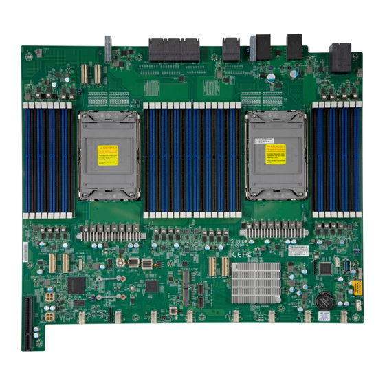
Chapter 1 Introduction Congratulations on purchasing your computer motherboard from an industry leader. Supermicro motherboards are designed to provide you with the highest standards in quality and performance. 1.1 Checklist This motherboard was designed to be used in an SMCI-proprietary chassis only as a part of an integrated, complete system solution. - Page 8 Super X12DGO-6 User's Manual X12DGO-6 Motherboard Image Note: All graphics shown in this manual were based upon the latest PCB revision available at the time of publication of the manual. The motherboard you received may or may not look exactly the same as the graphics shown in this manual.
- Page 9 BMC CODE UM15 UM16 DATA CLK UM13 UM14 M.2-H1 JM2_1 JBT1 I-SATA0~3 JHDD_PWR1 LEDM1 M.2-H2 I-SATA4~7 JM2_2 JHDD_PWR0 FAN6 FAN4 FAN8 FAN7 FAN5 FAN3 FAN2 FAN1 MEGERAC LICENSE X12DGO-6 Motherboard Layout Note: Components not documented are for internal testing only.
- Page 10 Super X12DGO-6 User's Manual Quick Reference JSLIM1A JSLIM1B JMB_E6 JMB_E2 JMB_E4 JMB_E5 JMB_AIOM JMB_E1 JMB_E3 PRESS FIT JMB_E5 JMB_E6 JMB_E1 JMB_E3 JMB_E2 JMB_E4 P2-DIMMG2 P2-DIMMG1 JMB_AIOM P1-DIMMC2 P2-DIMMH2 P1-DIMMC1 P2-DIMMH1 P1-DIMMD2 P2-DIMME2 P1-DIMMD1 CPU2 CPU1 P2-DIMME1 P1-DIMMA2 P2-DIMMF2 P1-DIMMA1 P2-DIMMF1...
- Page 11 BIOS flash VROC(JRK1) Intel VROC RAID key header for NVMe SSD Note: For detailed instructions on how to configure VROC RAID settings, please refer to the VROC RAID Configuration User's Guide posted on the web page under the link: http://www.supermicro.com/support/manuals/.
- Page 12 Super X12DGO-6 User's Manual Motherboard Features • Supports two 3rd Gen Intel Xeon Scalable Processors (in Socket P+ LGA 4189) with up to 40 CPU cores per CPU, and a TDP of up to 270W Memory • Supports up to 8TB 3DS LRDIMM/LRDIMM/3DS RDIMM/RDIMM DDR4 (288-pin) ECC memory with speeds of 3200/2933/2666 MHz in 32 memory slots and up to 8TB Intel Optane PMem 200 series with speeds of up to 3200 MHz Note 1: Intel®...
- Page 13 Chapter 1: Introduction Power Management • ACPI power management • Power button override mechanism • Power-on mode for AC power recovery • Wake-on-LAN • Power supply monitoring System Health Monitoring • Onboard voltage monitoring for +3.3V, +5V, +12V, +3.3V standby, +5V standby, Vcore, Vmem •...
- Page 14 Note 1: The CPU maximum thermal design power (TDP) is subject to chassis and heatsink cooling restrictions. For proper thermal management, please check the chas- sis and heatsink specifications. Note 2: For BMC configuration instructions, please refer to the Embedded BMC Con- figuration User's Guide available at http://www.supermicro.com/support/manuals/.
- Page 15 Chapter 1: Introduction X12DGO-6 CPU2-C1/C2 CPU2-D1/D2 CPU2-A1/A2 CPU2-B1/B2 CPU1-B1/B2 CPU1-A1/A2 CPU1-D1/D2 CPU1-C1/C2 PVCCIN_CPU1 12V PVCCIN_CPU1 12V VR13HC VR13HC 7+1 PHASE 7+1 PHASE 270W 270W 10.4/11.2G CPU2-H1/H2 CPU2-E1/E2 CPU1-E1/E2 CPU1-H1/H2 DMI2 PCI-E X16 G4 PCI-E X16 G4 Midplane Midplane PCI-E X16 G4...
-
Page 16: Processor And Chipset Support
1.2 Processor and Chipset Support Built upon the functionality and capability of the 3rd Gen Intel Xeon Scalable Processors (Socket P+) and the Intel C621A chipset, the X12DGO-6 motherboard increases energy efficiency and system performance for a multitude of applications such as high performance computing, artificial intelligence (AI), deep learning (DL), big data, and enterprise applications. -
Page 17: Special Features
Chapter 1: Introduction 1.3 Special Features Recovery from AC Power Loss The Basic I/O System (BIOS) provides a setting that determines how the system will respond when AC power is lost and then restored to the system. You can choose for the system to remain powered off (in which case you must press the power switch to turn it back on), or for it to automatically return to the power-on state. -
Page 18: Acpi Features
Windows operating systems. For detailed information regarding OS support, please refer to the Supermicro website. 1.6 Power Supply As with all computer products, a stable power source is necessary for proper and reliable operation. -
Page 19: Chapter 2 Installation
Chapter 2: Installation Chapter 2 Installation 2.1 Static-Sensitive Devices Electrostatic Discharge (ESD) can damage electronic com ponents. To avoid damaging your motherboard, it is important to handle it very carefully. The following measures are generally sufficient to protect your equipment from ESD. Precautions •... -
Page 20: Processor And Heatsink Installation
Thermal grease is pre-applied on a new heatsink. No additional thermal grease is needed. • Refer to the Supermicro website for updates on processor and memory support. • All graphics in this manual are for illustrations only. Your components may look different. - Page 21 Chapter 2: Installation 1. The 3rd Gen Intel Xeon Scalable Processor Processor Top View (3D) CPU Key Pin 1 = Cutout = CPU Key = Pin 1 Processor Top View...
- Page 22 Super X12DGO-6 User's Manual 2. The Processor Carrier = Cutout = Pin 1 = CPU Key Carrier Bottom View...
- Page 23 Chapter 2: Installation 3. Heatsink Note: Exercise extreme care when handling the heatsink. Pay attention to the edges of heatsink fins which can be sharp! To avoid damaging the heatsink, please do not apply excessive force on the fins when handling the heatsink.
- Page 24 Super X12DGO-6 User's Manual Overview of the CPU Socket The CPU socket is protected by a plastic protective cover. Plastic Protective Cover CPU Socket...
- Page 25 Chapter 2: Installation Overview of the Processor Carrier Assembly The processor carrier assembly contains a 3rd Gen Intel Xeon Scalable processor and a processor carrier. Carefully follow the instructions given in the installation section to place a processor into the carrier to create a processor carrier. 1.
- Page 26 Super X12DGO-6 User's Manual Overview of the Processor Heatsink Module The Processor Heatsink Module (PHM) contains a heatsink, a processor carrier, and a 3rd Gen Intel Xeon Scalable processor. 1. Heatsink (with Thermal Grease) Bottom View 2. Processor Carrier Bottom View 3.
- Page 27 Chapter 2: Installation Creating the Processor Carrier Assembly The processor carrier assembly contains a 3rd Gen Intel Xeon Scalable processor and a processor carrier. To create the processor carrier assembly, please follow the steps below: Note: Before installation, be sure to follow the instructions given on Page 1 and Page 2 of this chapter to properly prepare yourself for installation.
- Page 28 Super X12DGO-6 User's Manual 3. Locate the lever on the CPU socket and press the lever down as shown below. Lever 4. Using Pin 1 as a guide, carefully align the CPU keys (A and B) on the processor against the CPU keys on the carrier (a and b) as shown in the drawing below.
- Page 29 Chapter 2: Installation Creating the Processor Heatsink Module (PHM) After creating the processor carrier assembly, please follow the instructions below to mount the processor carrier into the heatsink to form the processor heatsink module (PHM). Note: If this is a new heatsink, the thermal grease has been pre-applied on the un- derside.
- Page 30 Super X12DGO-6 User's Manual Preparing the CPU Socket for Installation This motherboard comes with a plastic protective cover installed on the CPU socket. Remove it from the socket to install the Processor Heatsink Module (PHM). Gently pull up one corner of the plastic protective cover to remove it.
- Page 31 Chapter 2: Installation Preparing to Install the Processor Heatsink Module (PHM) into the CPU Socket After assembling the Processor Heatsink Module (PHM), you are ready to install it into the CPU socket. To ensure the proper installation, please follow the procedures below: 1.
- Page 32 Super X12DGO-6 User's Manual Installing the Processor Heatsink Module (PHM) 1. Align peek nut "A", which is next to the triangle (Pin 1) on the heatsink, against threaded fastener "a" on the CPU socket. Then align peek nuts "B", "C", and "D" on the heatsink against threaded fasteners "b", "c", and "d"...
- Page 33 Chapter 2: Installation Removing the Processor Heatsink Module from the CPU Socket Before removing the processor heatsink module (PHM) from the motherboard, unplug the AC power cord from all power supplies after shutting down the system. Then follow the steps below: 1.
- Page 34 Super X12DGO-6 User's Manual Removing the Processor Carrier Assembly from the Processor Heatsink Module (PHM) To remove the processor carrier assembly from the PHM, please follow the steps below: 1. Detach four plastic clips (marked a, b, c, d) on the processor carrier assembly from the four corners of heatsink (marked A, B, C, D) in the drawings below.
- Page 35 Chapter 2: Installation Removing the Processor from the Processor Carrier Assembly Once you have removed the processor carrier assembly from the PHM, you are ready to remove the processor from the processor carrier by following the steps below. 1. Unlock the lever from its locking position and push the lever upwards to disengage the processor from the processor carrier as shown in the right drawing below.
-
Page 36: Motherboard Installation
Super X12DGO-6 User's Manual 2.3 Motherboard Installation All motherboards have standard mounting holes to fit different types of chassis. Make sure that the locations of all the mounting holes for both the motherboard and the chassis match. Although a chassis may have both plastic and metal mounting fasteners, metal ones are highly recommended because they ground the motherboard to the chassis. - Page 37 Chapter 2: Installation Installing the Motherboard 1. Install the I/O shield into the back of the chassis, if applicable. 2. Locate the mounting holes on the motherboard. See the previous page for the location. 3. Locate the matching mounting holes on the chassis. Align the mounting holes on the motherboard against the mounting holes on the chassis.
-
Page 38: Memory Support And Installation
Memory Support The X12DGO-6 supports up to 8TB 3DS LRDIMM/LRDIMM/3DS RDIMM/RDIMM DDR4 (288-pin) ECC memory with speeds of 3200/2933/2666 MHz in 32 memory slots and up to 8TB Intel Optane PMem 200 Series with speeds of up to 3200 MHz. (See the notes below.) Note 1: Intel®... - Page 39 2 CPUs & 28 DIMMs CPU2: P2-DIMMA1/P2-DIMME1/P2-DIMMC1/P2-DIMMG1/P2-DIMMB1/P2-DIMMF1/P2-DIMMD1/P2-DIMMH1/ P2-DIMMA2/P2-DIMME2/P2-DIMMC2/P2-DIMMG2 CPU1: P1-DIMMA1/P1-DIMME1/P1-DIMMC1/P1-DIMMG1/P1-DIMMB1/P1-DIMMF1/P1-DIMMD1/P1-DIMMH1/ 2 CPUs & 32 DIMMs P1-DIMMA2/P1-DIMME2/P1-DIMMC2/P1-DIMMG2/P1-DIMMB2/P1-DIMMF2/P1-DIMMD2/P1-DIMMH2 (Note) CPU2: P2-DIMMA1/P2-DIMME1/P2-DIMMC1/P2-DIMMG1/P2-DIMMB1/P2-DIMMF1/P2-DIMMD1/P2-DIMMH1/ P2-DIMMA2/P2-DIMME2/P2-DIMMC2/P2-DIMMG2/P2-DIMMB2/P2-DIMMF2/P2-DIMMD2/P2-DIMMH2 Note: This memory configuration is recommended by Supermicro for optimal memory performance. Please use this configuration to maximize your memory performance.
- Page 40 Super X12DGO-6 User's Manual Intel Optane PMem 200 Series Memory Population Table Note: Intel® Optane™ Persistent Memory (PMem) 200 Series are supported by the 3rd Gen Intel Xeon Scalable (83xx/63xx/53xx/4314 Series) Processors. PMem 200 Series Population Table for X12DP 32-DIMM Motherboards (within 1 CPU socket)
- Page 41 Chapter 2: Installation Validation Matrix (DDR4 DIMMS with PMem 200 Series) DIMM Capacity (GB) Ranks Per DIMM DIMM Type & Data Width DRAM Density (Stack) 16Gb 1Rx8 1Rx4 16GB 32GB RDIMM (up to 3200) 1Rx8 16GB 32GB 1Rx4 32GB 64GB 4Rx4 (2H) 128GB RDIMM 3DS...
- Page 42 Super X12DGO-6 User's Manual DIMM Installation PRESS FIT JMB_E5 JMB_E6 JMB_E1 JMB_E2 JMB_E3 JMB_E4 JMB_AIOM 1. Insert the desired number of DIMMs into the memory CPU2 CPU1 slots based on the recommended DIMM population tables in the previous section. Locate DIMM memory slots on the motherboard as shown on the left.
- Page 43 Chapter 2: Installation DIMM Removal Press both release tabs on the ends of the DIMM module to unlock it. Once the DIMM module is loosened, remove it from the memory slot. Warning! Please do not use excessive force when pressing the release tabs on the ends of the DIMM socket to avoid causing any damage to the DIMM module or the DIMM socket.
-
Page 44: Front Control Panel
Super X12DGO-6 User's Manual 2.5 Front Control Panel Front I/O ports are available through the AOM-DGO-IO riser card. Riser card connector is located at JSLOT1 on the motherboard. See the figure below for the location of JSLOT1. 1. JSLOT1 PRESS FIT... - Page 45 AST 2600 BMC and accepts an RJ45 type cable. Refer to the LED Indicator Section for LAN LED information. PRESS FIT 1. JSLOT1 JMB_E5 JMB_E6 JMB_E1 JMB_E3 JMB_E2 JMB_E4 JMB_AIOM CPU2 CPU1 X12DGO-6 REV:1.01 DESIGNED IN USA BAR CODE BMC CODE UM15 UM16 DATA CLK UM13 UM14 M.2-H1 JM2_1 JBT1 I-SATA0~3...
- Page 46 Super X12DGO-6 User's Manual MISC Signal Riser Card Slot (JSLOT1) The Misc Signal riser card slot, located at JSLOT1, supports the AOM PIO i2XT add-on card on the motherboard. The AOM PIO i2XT can also provide two USB 3.1 connections for front access.
-
Page 47: Connectors And Headers
These connectors are used for an SMCI- proprietary server only. 1. JMB_E5 2. JMB_E6 PRESS FIT JMB_E5 JMB_E6 JMB_E1 JMB_E2 JMB_E3 JMB_E4 JMB_AIOM CPU2 CPU1 X12DGO-6 REV:1.01 DESIGNED IN USA BAR CODE BMC CODE UM15 UM16 DATA CLK UM13 UM14 M.2-H1 JM2_1 JBT1 I-SATA0~3... - Page 48 Super X12DGO-6 User's Manual Backplane Connectors Four backplane connectors (JMB_E1/JMB_E2/JMB_E3/JMB_E4), located next to the power connectors, provide PCIe signals to the backplane. 1. JMB_E1 1 2 3 2. JMB_E2 PRESS FIT JMB_E5 JMB_E6 JMB_E1 JMB_E2 JMB_E3 JMB_E4 3. JMB_E3 JMB_AIOM 4.
- Page 49 JMB_E4 2. FAN2 JMB_AIOM 3. FAN3 CPU2 CPU1 4. FAN4 5. FAN5 6. FAN6 7. FAN7 8. FAN8 9. FANA X12DGO-6 10. FANB REV:1.01 DESIGNED IN USA BAR CODE BMC CODE UM15 UM16 DATA CLK UM13 UM14 M.2-H1 JM2_1 JBT1...
- Page 50 Super X12DGO-6 User's Manual Backplane Hard Drive Power Connectors Two backplane HDD power connectors are located at JHDD_PWR0 and JHDD_PWR1. These power connectors provide power support for backplance HDDs in your system. Backplane Hard Drive Signal Connectors Two HDD signal connectors are located at JSLIM1A/JSLIM1B on the motherboard. These two connectors provide backplane HDD PCIe signals for your system.
- Page 51 Complex programmable logical devices. 1. JPRG1 2. JPRG2 PRESS FIT JMB_E5 JMB_E6 JMB_E1 JMB_E3 JMB_E2 JMB_E4 JMB_AIOM CPU2 CPU1 X12DGO-6 REV:1.01 DESIGNED IN USA BAR CODE BMC CODE UM15 UM16 DATA CLK UM13 UM14 M.2-H1 JM2_1 JBT1 I-SATA0~3...
- Page 52 Super X12DGO-6 User's Manual Riser Card Power Connector A riser card power connector is located at JPWR_RISER. It provides power support for the riser cards. Riser Card Connectors Four riser card connectors are located at JSLIM3A, JSLIM3B, JSLIM4A and JJSLIM4B.
- Page 53 Chapter 2: Installation M.2 Slot The X12DGO-6 motherboard has two M.2 slots (JM2_1/JM2_2). M.2 was formerly known as Next Generation Form Factor (NGFF) and serves to replace mini PCIe. M.2 allows for a variety of card sizes with increased functionality and spatial efficiency. The M.2 sockets on the motherboard support PCIe 3.0 x4 (32 Gb/s) SSD cards in the 2280 and 22110 form factors.
- Page 54 The JTPM1 header is used to connect a Trusted Platform Module (TPM)/Port 80, which is available from Supermicro (optional). A TPM/Port 80 connector is a security device that supports encryption and authentication in hard drives. It allows the motherboard to deny access if the TPM associated with the hard drive is not installed in the system.
- Page 55 1. VROC RAID Key (JRK1) PRESS FIT JMB_E5 JMB_E6 JMB_E1 JMB_E2 JMB_E3 JMB_E4 JMB_AIOM CPU2 CPU1 X12DGO-6 REV:1.01 DESIGNED IN USA BAR CODE BMC CODE UM15 UM16 DATA CLK UM13 UM14 M.2-H1 JM2_1 JBT1 I-SATA0~3...
- Page 56 Super X12DGO-6 User's Manual 4-pin BMC External I C Header A System Management Bus header for BMC 2.0 is located at JIPMB1. Connect the appropriate cable here to use the IPMB I C connection on your system. Refer to the table below for pin definitions.
- Page 57 Chapter 2: Installation I-SATA 3.0 Ports The X12DGO-6 has eight I-SATA 3.0 ports (I-SATA0-3, I-SATA4-7) on the motherboard. These SATA ports are supported by the Intel C621A chipset. PRESS FIT JMB_E5 JMB_E6 JMB_E1 JMB_E3 JMB_E2 JMB_E4 1. I-SATA0-3 JMB_AIOM 2. I-SATA4-7...
- Page 58 Super X12DGO-6 User's Manual Internal USB 3.0 Connector A Type A 3.0 USB connector is located at JUSB1 on the motherboard. JUSB1 can be accessed from the front side of the server via a proper USB cable (not included). 1. JUSB1...
-
Page 59: Jumper Settings
5. Replace the cover, reconnect the power cord(s), and power on the system. PRESS FIT JMB_E5 JMB_E6 JMB_E1 JMB_E2 JMB_E3 JMB_E4 JMB_AIOM 1. JBT1 CPU2 CPU1 X12DGO-6 REV:1.01 DESIGNED IN USA BAR CODE UM15 UM16 BMC CODE DATA CLK UM13 UM14 M.2-H1 JM2_1 I-SATA0~3... -
Page 60: Led Indicators
Super X12DGO-6 User's Manual 2.8 LED Indicators BMC LAN LEDs An BMC_LAN is located on the front I/O board. The LED on the right indicates activity, while the LED on the left indicates the speed of the connection. Refer to the table below for more information. - Page 61 Blinking PRESS FIT JMB_E5 JMB_E6 JMB_E1 JMB_E2 JMB_E3 JMB_E4 1. Onboard Power LED JMB_AIOM 2. BMC Heartbeat LED CPU2 CPU1 X12DGO-6 REV:1.01 DESIGNED IN USA BAR CODE BMC CODE UM15 UM16 DATA CLK UM13 UM14 M.2-H1 JM2_1 JBT1 I-SATA0~3 JHDD_PWR1 LEDM1 M.2-H2...
- Page 62 Super X12DGO-6 User's Manual M.2 LED Indicator Two M.2 LED indicators are located at LED1/LED2 on the motherboard. When M.2 LEDs is blinking, M.2 functions normally. Refer to the table below for more information. M.2 LED State LED Color Definition...
-
Page 63: Chapter 3 Troubleshooting
Chapter 3: Troubleshooting Chapter 3 Troubleshooting 3.1 Troubleshooting Procedures Use the following procedures to troubleshoot your system. If you have followed all of the procedures below and still need assistance, refer to the ‘Technical Support Procedures’ and/ or ‘Returning Merchandise for Service’ section(s) in this chapter. Always disconnect the AC power cord before adding, changing or, installing any non hot-swap hardware components. - Page 64 Super X12DGO-6 User's Manual No Video 1. If the power is on, but you do not have video, remove all add-on cards and cables. 2. Remove all memory modules and turn on the system (if the alarm is on, check the specs of memory modules, reset the memory, or try a different one).
- Page 65 Chapter 3: Troubleshooting When the System Becomes Unstable A. If the system becomes unstable during or after OS installation, check the following: 1. CPU/BIOS support: Make sure that your CPU is supported and that you have the latest BIOS installed in your system. 2.
-
Page 66: Technical Support Procedures
Before contacting Technical Support, please take the following steps. Also, please note that as a motherboard manufacturer, Supermicro also sells motherboards through its channels, so it is best to first check with your distributor or reseller for troubleshooting services. They should know of any possible problems with the specific system configuration that was sold to you. -
Page 67: Frequently Asked Questions
BIOS revision to make sure that it is newer than your BIOS before downloading. Note1: The SPI BIOS chip used on this motherboard cannot be removed. Send your motherboard back to our RMA Department at Supermicro for repair. Note2: For BIOS Update and Recovery instructions, please refer to the Firmware Update and Recovery Instructions for Supermicro's X12 Motherboards User's Guide posted at http://www.supermicro.com/support/manuals/. -
Page 68: Battery Removal And Installation
Super X12DGO-6 User's Manual 3.4 Battery Removal and Installation Battery Removal To remove the onboard battery, follow the steps below: 1. Power off your system and unplug your power cable. 2. Locate the onboard battery as shown below. 3. Using a tool such as a pen or a small screwdriver, push the battery lock outwards to unlock it. -
Page 69: Returning Merchandise For Service
For faster service, you can also request a RMA authorization online (http://www.supermicro. com/RmaForm/). This warranty only covers normal consumer use and does not cover damages incurred in shipping or from failure due to the alternation, misuse, abuse, or improper maintenance of products. -
Page 70: Chapter 4 Uefi Bios
UEFI BIOS 4.1 Introduction This chapter describes the AMIBIOS™ setup utility for the X12DGO-6 motherboard. The BIOS is stored on a chip and can be easily upgraded using the BMC WebUI or the SUM utility. Note: Due to periodic changes to the BIOS, some settings may have been added or deleted and might not yet be recorded in this manual. -
Page 71: Main Setup
Note: The time is in the 24-hour format. For example, 5:30 P.M. appears as 17:30:00. The date's default value is the BIOS build date after the RTC (Real Time Clock) reset. Supermicro X12DGO-6 BIOS Version This feature displays the version of the BIOS ROM used in the system. - Page 72 Super X12DGO-6 User's Manual Memory Information Total Memory This feature displays the total size of memory available in the system. Memory Speed This feature displays the speed of memory modules installed in the system.
-
Page 73: Advanced Setup Configurations
Chapter 4: UEFI BIOS 4.3 Advanced Setup Configurations Use the arrow keys to select the Advanced submenu and press <Enter> to access the submenu items: Warning: Take Caution when changing the Advanced settings. An incorrect value may cause the system to malfunction. When this occurs, restore the setting to the manufacturer default setting. - Page 74 Super X12DGO-6 User's Manual Boot Feature This submenu allows the user to configure Boot settings for the system. Quiet Boot Use this feature to select the screen between displaying POST messages or the OEM logo at bootup. Select Disabled to display the POST messages. Select Enabled to display the OEM logo instead of the normal POST messages.
- Page 75 Chapter 4: UEFI BIOS not capture Interrupt 19 immediately to allow the drives attached to these adaptors to function as bootable devices at bootup. The options are Immediate and Postponed. Re-try Boot When EFI (Extensible Firmware Interface) Boot is selected, the system BIOS will automatically reboot the system from an EFI boot device after an initial boot failure.
- Page 76 Super X12DGO-6 User's Manual Power Button Function This feature controls how the system shuts down when the power button is pressed. Select 4 Seconds Override to power off the system after the user presses and holds the power button for 4 seconds or longer. Select Instant Off to instantly power off the system as soon...
- Page 77 Chapter 4: UEFI BIOS CPU Configuration Warning: Setting the wrong values in the following sections may cause the system to malfunc- tion. Processor Configuration The following CPU information will be displayed: • Processor BSP Revision • Processor Socket •...
- Page 78 Super X12DGO-6 User's Manual CPU1 Core Disable Bitmap/CPU2 Core Disable Bitmap The following features will display: Available Bitmap: The available Bitmap will displayed. Core Disable Bitmap (Hex) Enter 0 to enable all CPU cores. Enter FFFFFFFFFFF to disable all CPU cores. Please note that at least one core per CPU must be enabled.
- Page 79 Chapter 4: UEFI BIOS Select Enable to enable the Intel Vanderpool Technology for Virtualization platform support, which will allow multiple operating systems to run simultaneously on the same computer to maximize system resources for performance enhancement. The options are Enable and Disable.
- Page 80 Super X12DGO-6 User's Manual ---------------------------------------------------------------- Software Guard Extension (SGX) -------------------------------------------------------------- Note: For SGX to work properly, please use the CPUs that support this feature and be sure to install one CPU per channel. SGX Factory Reset (Available when TME-MT is set to Enabled and the SGX feature is supported by the CPU used in the system) Select Enabled to reset the factory default setting for SGX (Software Guard Extension).
- Page 81 Chapter 4: UEFI BIOS Advanced Power Management Configuration Power Technology Select Energy Efficient to support power-saving mode. Select Custom to customize system power settings. Select Disabled to disable power-saving settings. The options are Disable, Energy Efficient, and Custom. Power Performance Tuning (Available when "Power Technology" is set to Custom) Select BIOS to allow the system BIOS to configure the Power-Performance Tuning Bias setting.
- Page 82 Super X12DGO-6 User's Manual Active SST-BF is set to Enabled) When this feature is set to Enable, the system BIOS will configure SST-BF High Priority Core settings so that system software does not have to configure these settings. The options are Enable and Disable.
- Page 83 Chapter 4: UEFI BIOS Enable Monitor/Mwait Select Enable to support Monitor and Mwait, which are two instructions in Streaming SIMD Extension 3 (SSE3), to improve synchronization between multiple threads for CPU performance enhancement. The options are Enable, and Disable. CPU C6 Report (Available when "Autonomous Core C-State" is set to Disable) Select Enable to allow the BIOS to report the CPU C6 state (ACPI C3) to the operating system.
- Page 84 Super X12DGO-6 User's Manual Chipset Configuration Warning: Setting the wrong values in the following items may cause the system to malfunction. North Bridge This feature allows the user to configure Intel North Bridge parameters. Uncore Configuration This section allows the user to configure the following Uncore settings: •...
- Page 85 Chapter 4: UEFI BIOS Degrade Precedence Use this feature to select the degrading precedence option for Ultra Path Interconnect (UPI) connections. Select Topology Precedent to degrade UPI features if the system options are in conflict. Select Feature Precedent to degrade UPI topology if system options are in conflict.
- Page 86 Super X12DGO-6 User's Manual Auto, Enable for Remote InvItoM Hybrid Push, InvItoM AllocFlow, Enable for Remote InvItoM Hybrid AllocNonAlloc, and Enable for Remote InvItoM and Remote WCiLF. SNC (Sub NUMA) Select Enable to use "Sub NUMA Clustering" (SNC), which supports full SNC (2-cluster) interleave and 1-way IMC interleave.
- Page 87 Chapter 4: UEFI BIOS Memory Configuration This feature allows the user to configure the Integrated Memory Controller (iMC) settings. Enforce POR (Plan of Record) Select POR to enforce POR restrictions for DDR4 memory frequency and voltage programming. The options are POR and Disable. PPR Type Post Package Repair (PPR) is a new feature available for the DDR4 Technology.
- Page 88 Super X12DGO-6 User's Manual Restore NVDIMM Modules (Available when "Enabled ADR" is set to Enable, and when NVDIMMs are detected/installed in the system) Select Enable to automatically restore the functionality and the features of NVDIMM modules. The options are Enable and Disable.
- Page 89 Chapter 4: UEFI BIOS Memory RAS (Reliability_Availability_Serviceability) Configuration Use this submenu to configure the following Memory RAS settings. Enable Pcode WA (Workaround) for SAI (Security Attribute of the Initiator) PG (Policy Group) Pcode, a register transfer language designed for reverse engineering, translates individual processor instructions into a sequence of Pcode operations in order to facilitate the construction of data-flow graphs and dissembling of processor instructions for machine application.
- Page 90 Super X12DGO-6 User's Manual Patrol Scrub Patrol Scrubbing is a process that allows the CPU to correct correctable memory errors detected in a memory module and send the corrections to the requestor (the original source). When this feature is set to Enable, the IO hub will read and write back one cache line every 16K cycles if there is no delay caused by internal processing.
- Page 91 Chapter 4: UEFI BIOS DMI Port MPSS (Maximum Payload Size Support) (Available for "CPU1 Configuration" Only) Use this feature to set the maximum payload size support in the PCIe Device Capabilities Register for the device installed in the DMI port. The options are Auto, 128B, and 256B. IOAT Configuration ...
- Page 92 Super X12DGO-6 User's Manual Intel VT for Directed I/O (VT-d) Intel® VT for Directed I/O (VT-d) Select Yes to use the Intel Virtualization Technology support for Direct I/O VT-d by reporting the I/O device assignments to the VMM (Virtual Machine Monitor) through the DMAR ACPI tables.
- Page 93 Chapter 4: UEFI BIOS CfgBar Size Use this feature to set the VMD Configuration Bar size (in bits. Minimum is 20 bits and maximum is 27 bits.) The default setting is 25 (bits). CfgBar Attribute Use this feature to set the VMD Configuration Bar attribute (e.g. 64-bit or Prefetchable.) The options are 32-bit non-prefetchable, 64-bit non-prefetchable, and 64-bit prefetch- able.
- Page 94 Super X12DGO-6 User's Manual South Bridge The following South Bridge information will display: • USB Module Version • USB Devices Legacy USB Support Select Enabled to support onboard legacy USB devices. Select Auto to disable legacy support if there are no legacy USB devices present. Select Disable to have all USB devices available for EFI applications only.
- Page 95 Chapter 4: UEFI BIOS Server ME (Management Engine) Configuration This feature displays the following general ME configuration settings: General ME Configuration • Oper. (Operation) Firmware Version • Backup Firmware Version • Recovery Firmware Version • ME Firmware Status #1/ME Firmware Status #2 •...
- Page 96 Super X12DGO-6 User's Manual SATA Configuration PCH SATA Configuration SATA Controller This feature enables or disables the onboard SATA controller supported by the Intel PCH chip. The options are Enable and Disable. Configure SATA as (Available when "SATA Controller" is set to Enable) Select AHCI to configure a SATA drive specified by the user as an AHCI drive.
- Page 97 Chapter 4: UEFI BIOS SATA RAID Option ROM/UEFI Driver (Available when "Configure SATA as" is set to RAID) Select EFI to load the EFI driver for system boot. Select Legacy to load a legacy driver for system boot. The options are Disable, EFI, and Legacy. SATA Port 0 - SATA Port 7 Hot Plug Select Enable to support Hot-plugging for the device installed on a selected SATA port...
- Page 98 Super X12DGO-6 User's Manual sSATA Configuration PCH sSATA Configuration sSATA Controller This featured enables or disables the onboard sSATA controller supported by the Intel PCH. The options are Enable and Disable. Configure sSATA as (Available when "sSATA Controller" is set to Enable) Select AHCI to configure an sSATA drive specified by the user as an AHCI drive.
- Page 99 Chapter 4: UEFI BIOS sSATA RAID Option ROM/UEFI Driver (Available when "Configure sSATA as" is set to RAID) Select EFI to load the EFI driver for system boot. Select Legacy to load a legacy driver for system boot. The options are Disable, EFI, and Legacy. sSATA Port 0 - sSATA Port 5 Hot Plug Select Enable to support Hot-plugging for the device installed on an sSATA port specified by...
- Page 100 Super X12DGO-6 User's Manual PCIe/PCI/PnP Configuration The following PCI information will be displayed: • PCI Bus Driver Version • PCI Devices Common Settings Above 4G Decoding (Available if the system supports 64-bit PCI decoding) Select Enabled to decode a PCI device that supports 64-bit in the space above 4G Address.
- Page 101 Chapter 4: UEFI BIOS Maximum Read Request Select Auto for the system BIOS to automatically set the maximum size for a read request for a PCIe device to enhance system performance. The options are Auto, 128 Bytes, 256 Bytes, 512 Bytes, 1024 Bytes, 2048 Bytes, and 4096 Bytes. MMCFG Base This feature determines how the lowest MMCFG (Memory-Mapped Configuration) base is assigned to onboard PCI devices.
- Page 102 Super X12DGO-6 User's Manual IPv6 HTTP Support Select Enabled to enable IPv4 HTTP boot support. If this feature is disabled, it will not create the IPv6 HTTP boot option. The options are Enabled and Disabled. PXE Boot Wait Time Use this feature to set the wait time (in seconds) upon which the system BIOS will wait for user to press the <ESC>...
- Page 103 Chapter 4: UEFI BIOS Super IO Configuration Super IO Chip AST2600 Serial Port 1 Configuration Serial Port Select Enabled to enable Serial Port 1. The options are Enabled and Disabled. Device Settings (Available when "Serial Port 1" is set to Enabled) This feature displays the base I/O port address and the Interrupt Request address of Serial Port 1.
- Page 104 Super X12DGO-6 User's Manual Serial Port 2 Configuration Serial Port Select Enabled to enable Serial Port 2. The options are Enabled and Disabled. Device Settings (Available when "Serial Port 2" is set to Enabled) This feature displays the base I/O port address and the Interrupt Request address of Serial Port 2.
- Page 105 Chapter 4: UEFI BIOS Serial Port Console Redirection COM 1 Console Redirection Select Enabled to enable COM Port 1 for Console Redirection, which will allow a client machine to be connected to a host machine at a remote site for networking. The options are Enabled and Disabled.
- Page 106 Super X12DGO-6 User's Manual Data Bits Use this feature to set the data transmission size for Console Redirection. The options are 7 (Bits) and 8 (Bits). Parity A parity bit can be sent along with regular data bits to detect data transmission errors. Select Even if the parity bit is set to 0, and the number of 1's in data bits is even.
- Page 107 Chapter 4: UEFI BIOS *If the feature above is set to Enabled, the following items will become available for configuration: Console Redirection Settings (for COM2/SOL) Use this feature to specify how the host computer will exchange data with the client computer, which is the remote computer used by the user.
- Page 108 Super X12DGO-6 User's Manual VT-UTF8 Combo Key Support Select Enabled to enable VT-UTF8 Combination Key support for ANSI/VT100 terminals. The options are Enabled and Disabled. Recorder Mode Select Enabled to capture the data displayed on a terminal and send it as text messages to a remote server.
- Page 109 Chapter 4: UEFI BIOS *If the feature above is set to Enabled, the following items will become available for user's configuration: Console Redirection Settings (for EMS) Out-of-Band Management Port This feature selects a serial port in a client server to be used by the Windows Emergency Management Services (EMS) to communicate with a remote host server.
- Page 110 Super X12DGO-6 User's Manual ACPI Settings Use this feature to configure Advanced Configuration and Power Interface (ACPI) power management settings for your system. NUMA Select Enabled to enable Non-Uniform Memory Access support to enhance system performance. The options are Enabled and Disabled.
- Page 111 Chapter 4: UEFI BIOS Trusted Computing (Available when a TPM device is installed and detected by the BIOS) When a TPM (Trusted-Platform Module) device is detected in your machine, the following information will display: Configuration • TPM 2.0 Device Found: •...
- Page 112 Super X12DGO-6 User's Manual SHA256 PCR Bank Select Enabled to enable SHA256 PCR Bank support to enhance system integrity and data security. The options are Enabled and Disabled. Pending Operation Use this feature to schedule a TPM-related operation to be performed by a security (TPM) device at the next system boot to enhance system data integrity.
- Page 113 Note 1: If the option for this feature (TXT Support) is set to Enabled, be sure to dis- able EV DFX (Device Function On-Hide support when it is present in the BIOS for the system to work properly Note 2: For more information on TPM, please refer to the TPM manual at http://www. supermicro.com/manuals/other.
- Page 114 Super X12DGO-6 User's Manual HTTP Boot Configuration When this submenu is selected, the following items will display: HTTP Boot Policy Use this feature to set the HTTP Boot policy. The options are Apply to all LANs, Apply to Each LAN, and Boot Priority #1 instantly.
- Page 115 Chapter 4: UEFI BIOS TLS Authenticate Configuration When this submenu is selected, the following items will display: Server CA Configuration This feature allows the user to configure the client certificate that is to be used by the server. Enroll Certification ...
- Page 116 Super X12DGO-6 User's Manual Delete Certification If this feature is set to Enable, the certificate enrolled in the system will be deleted. The options are Enable and Disable. Client Certification Configuration This feature allows the user to configure the client certificate to be used by the server.
- Page 117 Chapter 4: UEFI BIOS All CPU Information This submenu displays the detailed information of each CPU as detected by the BIOS as shown below. RAM Disk Configuration This feature allows the user to configure the settings for the RAM disks installed in the system. When you select this submenu and press <Enter>, the following items will display:...
- Page 118 Super X12DGO-6 User's Manual Disk Memory Type This feature specifies the type of memory that is available for you to create a RAM disk. The options are Boot Service Data and Reserved. Create Raw This feature allows the user to create a raw RAM disk from all available memory modules in the system.
- Page 119 Initiator Name Add an Attempt Delete Attempts Change Attempt Order Note: For detailed instructions on how to configure iSCSI settings, please refer to the iSCSI Configuration User's Guide posted on the web page under the link: http://www. supermicro.com/support/manuals/.
- Page 120 Super X12DGO-6 User's Manual Intel® Ethernet Controller X710 for 10GBASE-T -3C:EC:EF:ID:15:B0 Note: The display "X710 for 10GBASE-T -3C:EC:EF:ID:15:B0" is for illustration only. It is unique per system. Firmware Image Properties The following information will be displayed: • Option ROM Version •...
- Page 121 Chapter 4: UEFI BIOS The following information will be displayed as well: • UEFI Driver • Adapter PBA • Device Name • Chip Type • PCI Device ID • PCI Address • Link Status • MAC Address • Virtual MAC Address...
- Page 122 Super X12DGO-6 User's Manual VLAN Configuration (MAC: 3CECEF1D15B0) Note: The display "MAC: 3CECEFID15B0" is for illustration only. It is unique per sys- tem. Enter Configuration Menu Create New VLAN This feature allows the user to create a new VLAN.
- Page 123 Chapter 4: UEFI BIOS MAC: 3CECEF1D15B0 - IPv6 Network Configuration Note: The display "MAC: 3CECEFID15B0" is for illustration only. It is unique per sys- tem. Enter Configuration Menu The following features will display: • Interface Name • Interface Type •...
- Page 124 Super X12DGO-6 User's Manual MAC: 3CECEF1D15B0 - IPv4 Network Configuration Note: The display "MAC: 3CECEFID15B0" is for illustration only. It is unique per sys- tem. Configuration Configured Select Enabled to show whether the network address has been successfully configured or not.
- Page 125 Chapter 4: UEFI BIOS Intel® Ethernet Controller X710 for 10GBASE-T- 3C:EC:EF:ID:15:B1 Note: The display "X710 for 10GBASE-T -3C:EC:EF:ID:15:B1" is for illustration only. It is unique per system. Firmware Image Properties The following information will be displayed: • Option ROM Version •...
- Page 126 Super X12DGO-6 User's Manual The following information will be displayed as well: • UEFI Driver • Adapter PBA • Device Name • Chip Type • PCI Device ID • PCI Address • Link Status • MAC Address • Virtual MAC Address...
- Page 127 Chapter 4: UEFI BIOS VLAN Configuration (MAC: 3CECEF1D15B1) Note: The display "MAC: 3CECEFID15B1" is for illustration only. It is unique per sys- tem. Enter Configuration Menu Create New VLAN This feature allows the user to create a new VLAN. VLAN ID Use this feature to create a new LAN ID by using an existing VLAN or creating a new VLAN ID.
- Page 128 Super X12DGO-6 User's Manual MAC: 3CECEF1D15B1 - IPv6 Network Configuration Note: The display "MAC: 3CECEFID15B1" is for illustration only. It is unique per sys- tem. Enter Configuration Menu The following features will display: • Interface Name • Interface Type •...
- Page 129 Chapter 4: UEFI BIOS MAC: 3CECEF1D15B1 - IPv4 Network Configuration Note: The display "MAC: 3CECEFID15B1" is for illustration only. It is unique per sys- tem. Configured Select Enabled to show whether the network address has been successfully configured or not.
- Page 130 Super X12DGO-6 User's Manual Intel® Ethernet Controller X710 for 10 Gigabit SFP+- 3C:EC:EF:ID:15:B2 Note: The display "X710 for 10GBASE-T -3C:EC:EF:ID:15:B2" is for illustration only. It is unique per system. Firmware Image Properties The following information will be displayed: •...
- Page 131 Chapter 4: UEFI BIOS The following information will be displayed as well: • UEFI Driver • Adapter PBA • Device Name • Chip Type • PCI Device ID • PCI Address • Link Status • MAC Address • Virtual MAC Address...
- Page 132 Super X12DGO-6 User's Manual VLAN Configuration (MAC: 3CECEF1D15B2) Note: The display "MAC: 3CECEFID15B2" is for illustration only. It is unique per sys- tem. Enter Configuration Menu Create New VLAN This feature allows the user to create a new VLAN.
- Page 133 Chapter 4: UEFI BIOS MAC: 3CECEF1D15B2 - IPv6 Network Configuration Note: The display "MAC: 3CECEFID15B2" is for illustration only. It is unique per sys- tem. Enter Configuration Menu The following features will display: • Interface Name • Interface Type •...
- Page 134 Super X12DGO-6 User's Manual MAC: 3CECEF1D15B2 - IPv4 Network Configuration Note: The display "MAC: 3CECEFID15B2" is for illustration only. It is unique per sys- tem. Configured Select Enabled to show whether the network address has been successfully configured or not.
- Page 135 Chapter 4: UEFI BIOS INTEL SSDPE2NV076T8-BTLL8303063Z7P6BGN Note: The display "BTLL8303063Z7P6BGN" is for illustration only. It is unique per system. When you select this submenu and press <Enter>, the following information will display: PCI Generic Information • Bus Protocol: • PCI Vendor/Device ID: •...
- Page 136 Super X12DGO-6 User's Manual NVMe Drive Information • Drive Health: • Firmware Revision: • Option ROM Version: • Total Drive Capacity: • Number of Namespaces: • Namespace ID: • Device Capacity: • Device Size...
- Page 137 Chapter 4: UEFI BIOS INTEL SSDPE2NV076T8-BTLL832106MQ7P6BGN Note: The display "BTLL8303063Z7P6BGN" is for illustration only. It is unique per system. When you select this submenu and press <Enter>, the following information will display: PCI Generic Information • Bus Protocol: • PCI Vendor/Device ID: •...
- Page 138 Super X12DGO-6 User's Manual • Option ROM Version: • Total Drive Capacity: • Number of Namespaces: • Namespace ID: • Device Capacity: • Device Size...
- Page 139 Chapter 4: UEFI BIOS Intel® Ethernet Controller XXV710 for 25GbE SFP28 - 00:25:90:5E:87:B5 Note: The display "XXV710 for 25GbE SFP28 - 00:25:90:5E:87:B5" is for illustration only. It is unique per system. NIC Configuration Link Speed This feature displays the connection speed of a LAN port specified by the user. Wake On LAN If this feature is set to Enabled, the LAN port specified by the user will be enabled when the system is powered on.
- Page 140 Super X12DGO-6 User's Manual The following information will be displayed as well: • UEFI Driver • Adapter PBA • Device Name • Chip Type • PCI Device ID • PCI Address • Link Status • MAC Address • Virtual MAC Address...
- Page 141 Chapter 4: UEFI BIOS VLAN Configuration (MAC: 0025905E87B5) Note: The display "MAC: 0025905E87B5" is for illustration only. It is unique per system. Create New VLAN This feature allows the user to create a new VLAN. VLAN ID Use this feature to create a new LAN ID by using an existing VLAN or creating a new VLAN ID.
- Page 142 Super X12DGO-6 User's Manual MAC: 0025905E87B5 - IPv6 Network Configuration Note: The display "MAC: 0025905E87B5" is for illustration only. It is unique per system. The following features will display: • Interface Name • Interface Type • MAC Address •...
- Page 143 Chapter 4: UEFI BIOS MAC: 0025905E87B5 - IPv4 Network Configuration Note: The display "MAC: 0025905E87B5" is for illustration only. It is unique per system. Configured Select Enabled to show whether the network address has been successfully configured or not. The options are Enabled and Disabled. *If the feature above is set to Enabled, the following items will display: Enable DHCP Select Enabled to support Dynamic Host Configuration Protocol (DHCP) which will allow the...
- Page 144 Super X12DGO-6 User's Manual Intel® Optane™ Persistent Memory Configuration When you select this submenu and press <Enter>, the following screen will display: Intel® Optane™ Persistent Memory Configuration When you select this submenu and press <Enter>, the following screen will display: •...
- Page 145 Chapter 4: UEFI BIOS • DIMM Handle: This feature displays the unique handle assigned to the PMem module. • DIMM Physical ID: This feature displays the physical ID of the PMem module. • Manageability State: This feature indicates the manageability state of the PMem module. •...
- Page 146 Super X12DGO-6 User's Manual Show More Details Select Enabled to view more detailed information on the PMem module. The options are Disabled and Enabled. If this option is set to Enabled, the following items will display: • Serial Number •...
- Page 147 Chapter 4: UEFI BIOS • Manufacturer ID • Controller Revision ID • IS New • Memory Capacity • APP Direct Capacity • Unconfigured Capacity • Inaccessible Capacity • Reserved Capacity • Avg (Average) Power Limit [mW] • Memory Bandwidth Boost Feature •...
- Page 148 Super X12DGO-6 User's Manual • Overwrite PMem Module Status • Last Shutdown Time • Average Power Reporting Time Constant [mS] • Viral Policy Enable • Viral State • Thermal Throttle Loss % • Latched Last Shutdown Status • Unlatched Shutdown Status •...
- Page 149 Chapter 4: UEFI BIOS • Average Power 12V • Average Power 1.2V • eADR Enable • Previous Power Cycle eADR Enabled • Latch System Shutdown State • Previous Power Cycle Latch System Showdown State...
- Page 150 Super X12DGO-6 User's Manual Monitor Health This submenu displays the following health information on a memory module being monitored. • Sensor Type: This feature displays the type of health items that are being monitored. • Value: This feature displays the value of the monitor sensor mentioned above.
- Page 151 Chapter 4: UEFI BIOS Back to Main Menu Select this feature and press <Enter> to go back to the Intel® Optane™ Persistent Memory Configuration menu. Update Firmware Use this feature to select the firmware image to be loaded on the PMem module. After loading the firmware image, please reboot the system and select update for the firmware to take effect.
- Page 152 Super X12DGO-6 User's Manual Configure Security Use this feature to configure the security settings for all onboard PMem modules. State Select Enabled to configure the security settings for the PMem modules installed in the system. The options are Disabled and Enabled.
- Page 153 Chapter 4: UEFI BIOS Regions Current Configuration Region ID 1 When this submenu is selected, the following items will display: • Region ID: This feature displays the Region ID of the PMem module. • DIMM ID: This feature displays the DIMM ID of the PMem module. •...
- Page 154 Super X12DGO-6 User's Manual Provision This submenu configures the memory allocation goal for the onboard PMem memory modules. Create Goal Configuration When this submenu is selected, the following items will display: Create Goal Configuration for • Use this feature to select the target to create goal configuration for the PMem modules.
- Page 155 Chapter 4: UEFI BIOS Namespaces This subsection allows the user to select a namespace to view the following information on the selected namespace Namespace ID/Name/Heath Status 0x00000201 Select this feature and press <Enter>, the following items will display: • UUID •...
- Page 156 Super X12DGO-6 User's Manual Create Namespace Use this submenu to create a namespace. The following information will display: Name Region ID This feature displays the Region ID of the PMem module. The options are 0x0001 and 0x0001. Mode Use this feature to set the Namespace mode. The options are None and Sector.
- Page 157 Chapter 4: UEFI BIOS Total Capacity This feature allows the user to set the total PMem resource capacity allocated across all segments in the host server. PMem Module Capacities This section displays the following information: • Volatile: This feature specifies Volatile information of the PMem module. •...
- Page 158 Super X12DGO-6 User's Manual Diagnostics Perform Diagnostic Tests on DIMMs When you select this submenu and press <enter>, the following items will display: Choose Diagnostics Type: Use this feature to choose the type of diagnostics test to be performed on the PMem module...
- Page 159 Chapter 4: UEFI BIOS Preferences View and/or modify user preferences Default DIMM ID This feature allows the user to view and to modify the default DIMM ID as displayed on the screen. The options are Handle and UID. Capacity Units This feature allows the user to view and to set the default capacity unit of the selected PMem to be displayed on the screen.
-
Page 160: Event Logs
Super X12DGO-6 User's Manual 4.4 Event Logs Use this feature to configure Event Log settings. Note: After you've made any changes on a setting below, please reboot the system for the changes you've made to take effect. Change SMBIOS Event Log Settings... - Page 161 Chapter 4: UEFI BIOS SMBIOS Event Log Standard Settings Log System Boot Event Select Enabled to log system boot events. The options are Enabled and Disabled. MECI (Multiple Event Count Increment) Enter the increment value for the multiple event counter. Enter a number between 1 to 255. The default setting is 1.
-
Page 162: Bmc
Super X12DGO-6 User's Manual 4.5 BMC Use this feature to configure the BMC (Intelligent Platform Management Interface) settings. When you select this submenu and press <Enter>, the following information will display: • BMC Firmware Revision: This feature indicates the BMC firmware used in your system. - Page 163 Chapter 4: UEFI BIOS Custom EFI Logging Options Log EFI Status Codes This feature specifies the type of codes to be displayed when showing Log EFI Status Codes. The options are Disabled, Both, Error Code, and Progress Code. (Please reboot your system for the changes you've made to take effect.) BMC Network Configuration When you select this submenu, the following information will be displayed:...
- Page 164 Super X12DGO-6 User's Manual *************Configure IPv6 Support********** • IPv6 Address Status: This feature displays the status of IPv6 addresses. IPV6 Support Select Enabled for LAN1 IPV6 support. The options are Enabled and Disabled. *If this feature is set to Enabled, the following items will display: Configuration Address Source (Available when the item "Update BMC LAN...
-
Page 165: Security
Select Enabled to freeze the Lock Security feature for the HDDs to protect key data in hard drives from being altered. The options are Enabled and Disabled. Note: For detailed instructions on how to configure Security Boot settings, please refer to the Security Boot Configuration User's Guide posted on the web page under the link: http://www.supermicro.com/support/manuals/. - Page 166 Super X12DGO-6 User's Manual SMCI Security Erase Configuration This section allows the user to configure the SMCI-proprietary Security Erase settings. When this section is selected, the following features will display: • HDD Name: This feature displays the name of the HDD/SATA drive that is connected to the SMCI Security Erase Configuration submenu.
- Page 167 Note: For detailed instructions on how to configure Security Boot settings, please refer to the Security Boot Configuration User's Guide posted on the web page under the link: http://www.supermicro.com/support/manuals/. When you select this submenu and press the <Enter> key, the following items will display: •...
- Page 168 Super X12DGO-6 User's Manual Reset to Setup Mode This feature resets the system to Setup Mode. Export Secure Boot Variables This feature exports the NVRAM contents of Secure Boot variables to a storage device. Enroll EFI Image ...
- Page 169 Chapter 4: UEFI BIOS Forbidden Signatures Use this feature to enter and configure a set of values to be used as Forbidden Signatures for the system. These values also indicate sizes, keys, and key sources of the forbidden signatures. Select Update to update your "Forbidden Signatures". Select Append to append your "Forbidden Signatures".
-
Page 170: Boot
Super X12DGO-6 User's Manual 4.7 Boot Use this feature to configure Boot Settings: Boot Mode Select Use this feature to select the type of devices from which the system will boot. The options are LEGACY, UEFI (Unified Extensible Firmware Interface), and DUAL. - Page 171 Chapter 4: UEFI BIOS Add Boot Option This feature allows the user to specify the name for the new boot option. Path for Boot Option Use this feature to enter the path for the new boot option in the format fsx:\path\filename.efi. Boot Option File Path This feature allows the user to specify the file path for the new boot option.
- Page 172 Super X12DGO-6 User's Manual Delete Driver Option This feature allows the user to select a boot driver to delete from the boot prior- ity list. Delete Drive Option Select the target boot driver to delete from the boot priority list.
-
Page 173: Save & Exit
Chapter 4: UEFI BIOS 4.8 Save & Exit Select the Save & Exit menu from the BIOS setup screen to configure the settings below. Save Options Discard Changes and Exit Select this option to exit from the BIOS setup utility without making any permanent changes to the system configuration and reboot the computer. - Page 174 Super X12DGO-6 User's Manual Default Options Restore Default Values To set this feature, select Restore Default Values from the Exit menu and press <Enter> to load manufacturer default settings which are intended for maximum system performance but not for maximum stability.
-
Page 175: Appendix A Bios Post Codes
When BIOS performs the Power On Self Test, it writes checkpoint codes to I/O port 0080h. If the computer cannot complete the boot process, a diagnostic card can be attached to the computer to read I/O port 0080h (Supermicro p/n AOC-LPC80-20). For information on AMI updates, please refer to http://www.ami.com/products/. -
Page 176: Appendix B Software
USB/SATA DVD drive, or a USB flash drive, or the BMC KVM console. 2. Retrieve the proper RST/RSTe driver. Go to the Supermicro web page for your motherboard and click on "Download the Latest Drivers and Utilities", select the proper driver, and copy it to a USB flash drive. - Page 177 Appendix B: Software 4. During Windows Setup, continue to the dialog where you select the drives on which to install Windows. If the disk you want to use is not listed, click on the “Load driver” link at the bottom left corner. To load the driver, browse the USB flash drive for the proper driver files.
-
Page 178: Driver Installation
The Supermicro website contains drivers and utilities for your system at https://www. supermicro.com/wdl/driver. Some of these must be installed, such as the chipset driver. After accessing the website, go into the CDR_Images (in the parent directory of the above link) and locate the ISO file for your motherboard. Download this file to a USB flash drive or a DVD. -
Page 179: Superdoctor ® 5
B.3 SuperDoctor ® The Supermicro SuperDoctor 5 is a program that functions in a command-line or web-based interface for Windows and Linux operating systems. The program monitors such system health information as CPU temperature, system voltages, system power consumption, fan speed, and provides alerts via email or Simple Network Management Protocol (SNMP). -
Page 180: Bmc
When logging in to the BMC for the first time, please use the unique password provided by Supermicro to log in. You can change the unique password to a user name and password of your choice for subsequent logins. -
Page 181: Appendix C Standardized Warning Statements
The following statements are industry standard warnings, provided to warn the user of situations where a potential bodily injury may occur. Should you have questions or experience difficulty, contact Supermicro's Technical Support department for assistance. Only certified technicians should attempt to install or configure components. - Page 182 Super X12DGO-6 User's Manual Attention Danger d'explosion si la pile n'est pas remplacée correctement. Ne la remplacer que par une pile de type semblable ou équivalent, recommandée par le fabricant. Jeter les piles usagées conformément aux instructions du fabricant. ¡Advertencia! Existe peligro de explosión si la batería se reemplaza de manera incorrecta.
- Page 183 Appendix C: Standardized Warning Statements Product Disposal Warning! Ultimate disposal of this product should be handled according to all national laws and regulations. 製品の廃棄 この製品を廃棄処分する場合、 国の関係する全ての法律 ・ 条例に従い処理する必要があります。 警告 本产品的废弃处理应根据所有国家的法律和规章进行。 警告 本產品的廢棄處理應根據所有國家的法律和規章進行。 Warnung Die Entsorgung dieses Produkts sollte gemäß allen Bestimmungen und Gesetzen des Landes erfolgen.
Need help?
Do you have a question about the X12DGO-6 and is the answer not in the manual?
Questions and answers