Table of Contents
Advertisement
Quick Links
Advertisement
Table of Contents

Related Manuals for Supermicro X12SPZ-SPLN6F


Summary of Contents for Supermicro X12SPZ-SPLN6F
- Page 1 X12SPZ-SPLN6F/LN4F USER'S MANUAL Revision 1.0...
- Page 2 State of California, USA. The State of California, County of Santa Clara shall be the exclusive venue for the resolution of any such disputes. Supermicro's total liability for all claims will not exceed the price paid for the hardware product.
- Page 3 Processor with up to 40 cores and a TDP of 270W. Built with the Intel 621A chipset, the X12SPZ-SPLN6F/LN4Fsupports 2TB of ECC RDIMM and LRDIMM DDR4 with speeds of up to 3200MHz, SATA 3.0 ports, M.2 M-Key, Oculink, SlimSAS, 25G/10G fiber ports, and a Trusted Platform Module (TPM) header.
- Page 4 Super X12SPZ-SPLN6F/LN4F User's Manual Contacting Supermicro Headquarters Address: Super Micro Computer, Inc. 980 Rock Ave. San Jose, CA 95131 U.S.A. Tel: +1 (408) 503-8000 Fax: +1 (408) 503-8008 Email: marketing@supermicro.com (General Information) support@supermicro.com (Technical Support) Website: www.supermicro.com Europe Address: Super Micro Computer B.V.
-
Page 5: Table Of Contents
Preface Table of Contents Chapter 1 Introduction 1.1 Checklist ..........................8 Quick Reference .......................11 Quick Reference Table ......................12 Motherboard Features .......................14 1.2 Processor and Chipset Overview ..................18 1.3 Special Features ........................18 Recovery from AC Power Loss ..................18 1.4 System Health Monitoring ....................19 Onboard Voltage Monitors ....................19 Fan Status Monitor with Firmware Control ...............19 Environmental Temperature Control .................19... - Page 6 Super X12SPZ-SPLN6F/LN4F User's Manual Tools Needed ........................30 Location of Mounting Holes ....................30 Installing the Motherboard....................31 2.4 Memory Support and Installation ..................32 Memory Support ........................32 DDR4 Memory Support .....................32 General Guidelines for Optimizing Memory Performance ..........33 DIMM Installation ......................34 DIMM Removal .........................34 2.5 Rear I/O Ports ........................35...
- Page 7 Preface Chapter 4 UEFI BIOS 4.1 Introduction .........................72 4.2 Main Setup .........................73 4.3 Advanced ..........................75 4.4 Event Logs ........................117 4.5 IPMI ..........................119 4.6 Security ..........................122 4.7 Boot ..........................126 4.8 Save & Exit ........................128 Appendix A BIOS Codes Appendix B Software Appendix C Standardized Warning Statements Appendix D UEFI BIOS Recovery...
-
Page 8: Chapter 1 Introduction
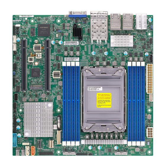
Introduction Congratulations on purchasing your computer motherboard from an industry leader. Supermicro motherboards are designed to provide you with the highest standards in quality and performance. In additon to the motherboard, several important parts that are included in the retail box are listed below. - Page 9 Chapter 1: Introduction Figure 1-1. X12SPZ-SPLN6F Motherboard Image Note: All graphics shown in this manual were based upon the latest PCB revision available at the time of publication of the manual. The motherboard you received may or may not look exactly the same as the graphics shown in this manual.
- Page 10 Super X12SPZ-SPLN6F/LN4F User's Manual Figure 1-2. X12SPZ-SPLN6F Motherboard Layout (not drawn to scale) X12SPZ-LN4F REV: 2.00 DESIGNED IN USA JSTBY1 JBM2 JPL1 JPFR1 JBM1 JPFR3 IPMI LAN LAN3/4 LAN1/2 JPFR2 USB4/5 (3.0) JCPLD1 LEDBMC SRW4 JLANLED1_1 LAN6 LAN5 BAR CODE...
-
Page 11: Quick Reference
Chapter 1: Introduction Quick Reference JBM1 SFP LAN6 LAN3/4 JPDB1 LEDBMC LAN1/2 UIDLED JPL1 SRW4 SFP LAN5 IPMI LAN USB4/5 (3.0) JSTBY1 X12SPZ-LN4F REV: 2.00 DESIGNED IN USA JSTBY1 JBM2 JPL1 JBM2 JPFR1 JBM1 JPFR3 IPMI LAN LAN3/4 LAN1/2 JPFR2 USB4/5 (3.0) JCPLD1 LEDBMC... -
Page 12: Quick Reference Table
Super X12SPZ-SPLN6F/LN4F User's Manual Quick Reference Table Jumper Description Default Setting JBM1 Disable IPMI Share LAN Pins 1-1 (Enabled) JBM2 Disable IPMI Dedicated/Share LAN Pins 1-1 (Enabled) JBT1 CMOS Clear Open (Normal) JNS1 OCulink to 4x SATA or PCIe x4 Selection... - Page 13 Chapter 1: Introduction Connector Description JRK1 Intel RAID Key Header JSLIM1 PCIe 4.0 x8 SlimSAS Connector JSLIM2 PCIe 4.0 x4 SlimSAS Connector JSTBY1 Standby Power Header JTPM1 Trusted Platform Module/Port 80 Connector LAN1/2, LAN3/4 LAN RJ45 Ports LAN5, LAN6 25G/10G Fiber LAN Ports MH2 - MH9 Mounting Holes P1_NVME0...
-
Page 14: Motherboard Features
Super X12SPZ-SPLN6F/LN4F User's Manual Motherboard Features Motherboard Features • Supports a 3rd Generation Intel Xeon Scalable Processor with up to 40 cores Memory • Up to 2TB of ECC RDIMM and LRDIMM DDR4 memory with speeds of up to 3200MHz in eight memory slots DIMM Size •... - Page 15 Chapter 1: Introduction Motherboard Features Peripheral Devices • Two front accessible USB 2.0 headers with four USB connections (USB0/1, USB2/3) • One USB 3.0 header with two connections (USB6/7) • Two USB 3.0 ports on the rear I/O panel (USB4/5) BIOS •...
- Page 16 Note 1: The CPU maximum thermal design power (TDP) is subject to chassis and heatsink cooling restrictions. For proper thermal management, please check the chas- sis and heatsink specifications for proper CPU TDP sizing. Note 2: For IPMI configuration instructions, please refer to the Embedded IPMI Con- figuration User's Guide available at http://www.supermicro.com/support/manuals/.
- Page 17 Chapter 1: Introduction Figure 1-3. System Block Diagram PVCCIN_CPU1 VR13HC Supports Barlow Pass Supports Barlow Pass 7+1 PHASE DIMMG1 270W DIMMC1 DIMMH1 DIMMD1 DIMME1 DIMMA1 DIMMF1 DIMMB1 CPU#1 PCI-E X16-Gen4 JPCIE4 PE2[0:15] PCI-E X8-Gen3 ZSFP+ PE0[8:15] BROADCOM Rear I/O PCI-E X16-Gen4 25G *2 PE1[0:15] BCM57414...
-
Page 18: Processor And Chipset Overview
1.2 Processor and Chipset Overview Built upon the functionality and capability of the 3rd Generation Intel Xeon Scalable Processor and the Intel 621A chipset, the X12SPZ-SPLN6F/LN4F motherboard provides system performance, power efficiency, and feature sets to address the needs of next-generation computer users. -
Page 19: System Health Monitoring
Plug and Play, and an operating system-independent interface for configuration control. ACPI leverages the Plug and Play BIOS data structures, while providing a processor architecture-independent implementation that is compatible with appropriate Windows operating systems. For detailed information regarding OS support, please refer to the Supermicro website. -
Page 20: Power Supply
It is even more important for processors that have high CPU clock rates where noisy power transmission is present. The X12SPZ-SPLN6F/LN4F motherboard accommodates a 24-pin ATX power supply. Although most power supplies generally meet the specifications required by the CPU, some are inadequate. -
Page 21: Chapter 2 Installation
Chapter 2: Installation Chapter 2 Installation 2.1 Static-Sensitive Devices Electrostatic Discharge (ESD) can damage electronic com ponents. To avoid damaging your system board, it is important to handle it very carefully. The following measures are generally sufficient to protect your equipment from ESD. Precautions •... -
Page 22: Processor And Heatsink Installation
Thermal grease is pre-applied on a new heatsink. No additional thermal grease is needed. • Refer to the Supermicro website for updates on processor support. • All graphics in this manual are for illustrations only. Your components may look different. -
Page 23: Overview Of The Processor Carrier Assembly
Chapter 2: Installation Overview of the Processor Carrier Assembly The processor carrier assembly contains the 3rd Generation Intel Xeon Scalable Processor and a processor carrier. 1. Processor 2. Processor Carrier Overview of the CPU Socket The CPU socket is protected by a plastic protective cover. 1. -
Page 24: Overview Of The Processor Heatsink Module
Super X12SPZ-SPLN6F/LN4F User's Manual Overview of the Processor Heatsink Module The Processor Heatsink Module (PHM) contains a heatsink, a processor carrier, and the processor. 1. Heatsink with Thermal Grease 2. Processor Carrier 3. Processor Processor Heatsink Module... -
Page 25: Creating The 3Rd Generation Intel Xeon Scalable Processor Carrier Assembly
Chapter 2: Installation Creating the 3rd Generation Intel Xeon Scalable Processor Carrier Assembly To install the processor into the processor carrier, follow the steps below: 1. Hold the processor with the LGA lands (gold contacts) facing up. Locate the small, gold triangle in the corner of the processor and the corresponding hollowed triangle on the processor carrier. -
Page 26: Assembling The Processor Heatsink Module
Super X12SPZ-SPLN6F/LN4F User's Manual Assembling the Processor Processor Carrier Assembly (Upside Down) Heatsink Module After creating the processor carrier assembly for the processor, mount it onto the heatsink to create the processor heatsink module (PHM): 1. Note the label on top of the heatsink, which marks the heatsink mounting holes as 1, 2, 3, and 4. -
Page 27: Preparing The Cpu Socket For Installation
Chapter 2: Installation Preparing the CPU Socket for Installation This motherboard comes with a plastic protective cover installed on the CPU socket. Remove it from the socket to install the Processor Heatsink Module (PHM). Gently pull up one corner of the plastic protective cover to remove it. -
Page 28: Installing The Processor Heatsink Module
Super X12SPZ-SPLN6F/LN4F User's Manual Installing the Processor Heatsink Module After assembling the Processor Heatsink Module (PHM), install the PHM onto the CPU socket: 1. Align hole 1 of the heatsink with the printed triangle on the CPU socket. See the left image below. -
Page 29: Removing The Processor Heatsink Module
Chapter 2: Installation Removing the Processor Heatsink Module Remove the screws in the sequence of 4, 3, 2, 1 Before removing the processor heatsink module (PHM) from the motherboard, shut down the system and then unplug the AC power cord from all power supplies. -
Page 30: Motherboard Installation
Super X12SPZ-SPLN6F/LN4F User's Manual 2.3 Motherboard Installation All motherboards have standard mounting holes to fit different types of chassis. Make sure that the locations of all the mounting holes for both the motherboard and the chassis match. Although a chassis may have both plastic and metal mounting fasteners, metal ones are highly recommended because they ground the motherboard to the chassis. -
Page 31: Installing The Motherboard
Chapter 2: Installation Installing the Motherboard 1. Install the I/O shield into the back of the chassis, if applicable. 2. Locate the mounting holes on the motherboard. See the previous page for the location. 3. Locate the matching mounting holes on the chassis. Align the mounting holes on the motherboard against the mounting holes on the chassis. -
Page 32: Memory Support And Installation
Memory Support The X12SPZ-SPLN6F/LN4F supports up to 2TB of ECC RDIMM and LRDIMM DDR4 memory with speeds of up to 3200MHz in eight memory slots. Refer to the table below for the recommended DIMM population order. -
Page 33: General Guidelines For Optimizing Memory Performance
Chapter 2: Installation General Guidelines for Optimizing Memory Performance • Always use DDR4 memory of the same type, size, and speed. • Mixed DIMM speeds can be installed. However, all DIMMs will run at the speed of the slowest DIMM. •... -
Page 34: Dimm Installation
Super X12SPZ-SPLN6F/LN4F User's Manual DIMM Installation X12SPZ-LN4F REV: 2.00 1. Insert DIMM modules in the following DESIGNED IN USA JSTBY1 JBM2 JPL1 JPFR1 JBM1 JPFR3 IPMI LAN LAN3/4 LAN1/2 order: DIMMC1, DIMMD1, DIMMA1, JPFR2 USB4/5 (3.0) JCPLD1 LEDBMC SRW4 JLANLED1_1... -
Page 35: Rear I/O Ports
Chapter 2: Installation 2.5 Rear I/O Ports See Figure 2-1 below for the locations and descriptions of the various I/O ports on the rear of the motherboard. X12SPZ-LN4F REV: 2.00 DESIGNED IN USA JSTBY1 JBM2 JPL1 JPFR1 JBM1 JPFR3 IPMI LAN LAN3/4 LAN1/2 JPFR2... - Page 36 Super X12SPZ-SPLN6F/LN4F User's Manual VGA Port A video (VGA) port is located on the I/O back panel. Refer to the board layout below for the location. LAN Ports The motherboard has four 1GbE LAN ports (LAN1/2, LAN3/4) and two 25G SFP28 LAN ports (LAN5, LAN6) located on the I/O back panel.
- Page 37 Chapter 2: Installation Universal Serial Bus (USB) Ports There are two USB 3.0 ports (USB4/5) on the I/O back panel and two USB 2.0 headers (USB0/1 and USB2/3) on the motherboard. The motherboard also has one USB 3.0 header (USB6/7). The onboard headers can be used to provide front side USB access with a cable (not included).
- Page 38 Super X12SPZ-SPLN6F/LN4F User's Manual Unit Identifier Switch/UID LED Indicator A Unit Identifier (UID) switch and an LED indicator are located on the motherboard. The UID switch is located at UID. The UIDLED is located next to the UID switch. When you press the UID switch, the UID LED will be turned on.
-
Page 39: Front Control Panel
JF1 contains header pins for various buttons and indicators that are normally located on a control panel at the front of the chassis. These connectors are designed specifically for use with Supermicro chassis. See the figure below for the descriptions of the front control panel buttons and LED indicators. - Page 40 Super X12SPZ-SPLN6F/LN4F User's Manual Power Button The Power Button connection is located on pins 1 and 2 of JF1. Momentarily contacting both pins will power on/off the system. This button can also be configured to function as a suspend button (with a setting in the BIOS - see Chapter 4). To turn off the power when the system is in suspend mode, press the button for 4 seconds or longer.
- Page 41 Chapter 2: Installation Power Fail The Power Fail LED connection is located at pins 5 and 6. Refer to the table below for pin definitions. Power Fail LED Pin Definitions (JF1) Pin# Definition 3.3V Power Fail LED Information LED (OH/Fan Fail/PWR Fail/UID LED) The Information LED (OH/Fan Fail/PWR Fail/UID LED) connection is located on pins 7 and 8 of JF1.
- Page 42 Super X12SPZ-SPLN6F/LN4F User's Manual NIC1/NIC2 (LAN1/LAN2) The NIC (Network Interface Controller) LED connection for LAN port 1 is located on pins 11 and 12 of JF1, and LAN port 2 is on pins 9 and 10. Attach the NIC LED cables here to display network activity.
- Page 43 Chapter 2: Installation Power LED The Power LED connection is located on pins 15 and 16 of JF1. Refer to the table below for pin definitions. Power LED Pin Definitions (JF1) Pins Definition +3.3V Stby PWR LED NMI Button The non-maskable interrupt button header is located on pins 19 and 20 of JF1. Refer to the table below for pin definitions.
-
Page 44: Connectors
Super X12SPZ-SPLN6F/LN4F User's Manual 2.7 Connectors Power Connections Power Connectors JPW1 is the 24-pin power connector for ATX power source. JPV1 is the 12V DC power connector that provides power to the CPU in conjunction with JPW1 or it can be used as the sole 12V DC only power input when JPW1 is not in use. -
Page 45: Headers
Chapter 2: Installation Headers Fan Headers There are six 4-pin fan headers (FAN1 - FAN4, FANA, FANB) on the motherboard. All these 4-pin fan headers are backwards compatible with the traditional 3-pin fans. However, fan speed control is available for 4-pin fans only by Thermal Management via the IPMI 2.0 interface. Refer to the table below for pin definitions. - Page 46 Super X12SPZ-SPLN6F/LN4F User's Manual SGPIO Headers There is one Serial Link General Purpose Input/Output (S-SGPIO1) header located on the motherboard. Refer to the tables below for pin definitions. SGPIO Header Pin Definitions Pin# Definition Pin# Definition SATA Clock SATA Load...
- Page 47 Port 80 connection. Use this header to enhance system performance and data security. Refer to the table below for pin definitions. Please go to the following link for more information on the TPM: http://www.supermicro.com/manuals/other/TPM.pdf. Trusted Platform Module Header Pin Definitions...
- Page 48 Super X12SPZ-SPLN6F/LN4F User's Manual Standby Power The Standby Power header is located at JSTBY1 on the motherboard. You must have a card with a Standby Power connector and a cable to use this feature. Refer to the table below for pin definitions.
- Page 49 Chapter 2: Installation 4-pin External BMC I C Header A System Management Bus header for IPMI 2.0 is located at JIPMB1. Connect a cable to this header to use the IPMB I C connection on your system. Refer to the table below for pin definitions.
- Page 50 Super X12SPZ-SPLN6F/LN4F User's Manual Speaker/Power LED Pins 1-3 of JD1 are used for power LED indication, and pins 4-7 are for the speaker. Please note that the speaker connector pins (4-7) are used with an external speaker. Refer to the tables below for pin definitions.
- Page 51 Chapter 2: Installation NVMe I C Header Connector JNVI C1 is a management header for the Supermicro AOC NVMe PCIe peripheral cards. Connect the I C cable to this connector. Intel RAID Key Header The JRK1 header allows the user to enable RAID functions for NVMe connections. Refer to the table below for pin definitions.
- Page 52 SATA 3.0 Ports This motherboard has two SATA 3.0 ports (S-SATA0, S-SATA1). S-SATA1 can be used with Supermicro SuperDOM's SATA DOM connectors with power pins built in, and do not require external power cables. Supermicro SuperDOMs are backward compatible with regular SATA HDDs or SATA DOMs that need external power cables.
- Page 53 Chapter 2: Installation LAN Port Activity LED JLANLED1 is the LAN3 - LAN6 activity LED for X12SPZ-SPLN6F, and JLANLED1_1 is the LAN3 - LAN4 activity LED for X12SPZ-LN4F. JLANLED1 JLANLED1_1 Pin Definitions Pin Definitions Pin# Definition Pin# Definition Pin# Definition...
- Page 54 Super X12SPZ-SPLN6F/LN4F User's Manual Slim SAS Connectors The slim SAS connector at JSLIM1 supports PCIe 4.0 x8 devices, and the slim SAS connector at JSLIM2 supports PCIe 4.0 x4 devices. 1. JSLIM1 2. JSLIM2 X12SPZ-LN4F REV: 2.00 DESIGNED IN USA...
- Page 55 Chapter 2: Installation General Purpose I/O Header The JGP1 (General Purpose Input/Output) header is a general purpose I/O expander on a pin header via the SMBus. Refer to the table below for pin definitions. JGP1 Header Pin Definitions Pin# Definition GPIO Pin Memory Address +3.3V Stby...
-
Page 56: Jumper Settings
Super X12SPZ-SPLN6F/LN4F User's Manual 2.8 Jumper Settings How Jumpers Work To modify the operation of the motherboard, jumpers can be used to choose between optional settings. Jumpers create shorts between two pins to change the function of the connector. Pin 1 is identified with a square solder pad on the printed circuit board. - Page 57 Chapter 2: Installation LAN Port Enable/Disable Use JPL1 to enable or disable LAN5 and LAN6, and JPL2 to enable or disable LAN1 - LAN4. The default setting is Enabled. LAN Port Enable/Disable Jumper Settings Jumper Setting Definition Pins 1-2 Enabled (Default) Pins 2-3 Disabled 1.
- Page 58 Super X12SPZ-SPLN6F/LN4F User's Manual Management Engine (ME) Recovery Use jumper JPME1 to select ME Firmware Recovery mode, which will limit resource allocation for essential system operation only in order to maintain normal power operation and management. In the single operation mode, online upgrade will be available via Recovery mode. Refer to the table below for jumper settings.
- Page 59 Chapter 2: Installation IPMI Share LAN Enable/Disable Set the JBM1 jumper to enabled to share i350 LAN with IPMI. IPMI Share LAN Enable/Disable Jumper Settings Jumper Setting Definition Pins 1-2 (Open) Enabled (Default) Pins 1-2 (Short) Disabled IPMI Dedicated/Share LAN Enable/Disable Use JBM2 to enable or disable the dedicated IPMI LAN port.
- Page 60 Super X12SPZ-SPLN6F/LN4F User's Manual VGA Enable/Disable JPG1 allows you to enable or disable the VGA port using the onboard graphics controller. VGA Enable/Disable Jumper Settings Jumper Setting Definition Pins 1-2 Enabled Pins 2-3 Disabled OCulink Seleciton Use JNS1 to select the OCulink lane. Refer to the table below for lane options.
- Page 61 Chapter 2: Installation Onboard TPM Enable/Disable Use JPT1 to enable or disable the onboard TPM. TPM Enable/Disable Jumper Settings Jumper Setting Definition Pins 1-2 Enabled Pins 2-3 Disabled COM1 Function Seleciton Use JPDB1 to select the COM1 function. Refer to the table below for jumper settings. COM1 Function Selection Jumper Settings Jumper Setting...
-
Page 62: Led Indicators
Super X12SPZ-SPLN6F/LN4F User's Manual 2.9 LED Indicators Onboard Power LED LEDPWR is the onboard Power LED. When this LED is on, the system is on. Be sure to turn off the system and unplug the power cord before removing or installing components. Refer to the table below for more information. - Page 63 Chapter 2: Installation LAN LEDs There are four LAN ports (LAN1 - LAN4) on the I/O back panel of the motherboard. Each LAN port has two LEDs. The green LED indicates activity, while the other Link LED may be green, amber, or off to indicate the speed of the connection.
-
Page 64: Chapter 3 Troubleshooting
Super X12SPZ-SPLN6F/LN4F User's Manual Chapter 3 Troubleshooting 3.1 Troubleshooting Procedures Use the following procedures to troubleshoot your system. If you have followed all of the procedures below and still need assistance, refer to the ‘Technical Support Procedures’ and/ or ‘Returning Merchandise for Service’ section(s) in this chapter. Always disconnect the AC power cord before adding, changing or installing any non hot-swap hardware components. -
Page 65: No Video
Chapter 3: Troubleshooting No Video 1. If the power is on, but you have no video, remove all add-on cards and cables. 2. Use the speaker to determine if any beep codes are present. Refer to Appendix A for details on beep codes. 3. -
Page 66: Losing The System's Setup Configuration
Super X12SPZ-SPLN6F/LN4F User's Manual Losing the System's Setup Configuration 1. Make sure that you are using a high-quality power supply. A poor-quality power supply may cause the system to lose the CMOS setup information. Refer to Chapter 2 for details on recommended power supplies. - Page 67 Chapter 3: Troubleshooting 3. Using the minimum configuration for troubleshooting: Remove all unnecessary components (starting with add-on cards first), and use the minimum configuration (but with the CPU and a memory module installed) to identify the trouble areas. Refer to the steps listed in Section A above for proper troubleshooting procedures.
-
Page 68: Technical Support Procedures
Before contacting Technical Support, please take the following steps. Also, please note that as a motherboard manufacturer, Supermicro also sells motherboards through its channels, so it is best to first check with your distributor or reseller for troubleshooting services. They should know of any possible problems with the specific system configuration that was sold to you. -
Page 69: Frequently Asked Questions
Note: The SPI BIOS chip used on this motherboard cannot be removed. Send your motherboard back to our RMA Department at Supermicro for repair. For BIOS Recovery instructions, please refer to the AMI BIOS Recovery Instructions posted at http://www. -
Page 70: Battery Removal And Installation
Super X12SPZ-SPLN6F/LN4F User's Manual 3.4 Battery Removal and Installation Battery Removal To remove the onboard battery, follow the steps below: 1. Power off your system and unplug your power cable. 2. Locate the onboard battery as shown below. 3. Using a tool such as a pen or a small screwdriver, push the battery lock outwards to unlock it. -
Page 71: Returning Merchandise For Service
For faster service, you can also request a RMA authorization online (http://www.supermicro. com/RmaForm/). This warranty only covers normal consumer use and does not cover damages incurred in shipping or from failure due to the alternation, misuse, abuse or improper maintenance of products. -
Page 72: Chapter 4 Uefi Bios
Super X12SPZ-SPLN6F/LN4F User's Manual Chapter 4 UEFI BIOS 4.1 Introduction This chapter describes the AMIBIOS™ Setup utility for the motherboard. The BIOS is stored on a chip and can be easily upgraded using a flash program. Note: Due to periodic changes to the BIOS, some settings may have been added or deleted and might not yet be recorded in this manual. -
Page 73: Main Setup
Note: The time is in the 24-hour format. For example, 5:30 P.M. appears as 17:30:00. The date's default value is the BIOS build date after RTC reset. Supermicro X12SPZ-SPLN6F/LN4F BIOS Version This feature displays the version of the BIOS ROM used in the system. - Page 74 Super X12SPZ-SPLN6F/LN4F User's Manual Memory Information Total Memory This feature displays the total size of memory available in the system.
-
Page 75: Advanced
Chapter 4: BIOS 4.3 Advanced Use the arrow keys to select the Advanced menu and press <Enter> to access the menu features. Warning: Take caution when changing the Advanced settings. An incorrect value, a very high DRAM frequency, or an incorrect DRAM timing setting may make the system unstable. When this occurs, revert to default manufacturer settings. - Page 76 Super X12SPZ-SPLN6F/LN4F User's Manual Wait For "F1" If Error Use this feature to force the system to wait until the "F1" key is pressed if an error occurs. The options are Disabled and Enabled. INT19 (Interrupt 19) Trap Response Interrupt 19 is the software interrupt that handles the boot disk function. When this feature is set to Immediate, the ROM BIOS of the host adapters will "capture"...
- Page 77 Chapter 4: BIOS CPU Configuration The following CPU information will display: • Processor BSP Revision • Processor Socket • Processor ID • Processor Frequency • Processor Max Ratio • Processor Min Ratio • Microcode Revision • L1 Cache RAM (Per Core) •...
- Page 78 Super X12SPZ-SPLN6F/LN4F User's Manual Adjacent Cache Prefetch The CPU prefetches the cache line for 64 bytes if this feature is set to Disabled. The CPU prefetches both cache lines for 128 bytes as comprised if this feature is set to Enable. The options are Enable and Disable.
- Page 79 Chapter 4: BIOS TME, TME-MT, TDX Total Memory Encryption Use this feature to enable or disable total memory encryption. The options are Disabled and Enabled. Limit CPU PA to 46 Bits Use this feature to limit the CPU physical address to 46 bits to support older hyper-v. The options are Disable and Enable.
- Page 80 Super X12SPZ-SPLN6F/LN4F User's Manual Activate SST-BF Use this feature to enable or disable Intel Speed Select Technology Base Frequency. The options are Disable and Enable. *If the feature above is set to Enable, the next feature will be available for con-...
- Page 81 Chapter 4: BIOS Hardware PM State Control Hardware P-States This setting allows you to select between OS and hardware-controlled P-states. Select- ing Native Mode allows the OS to choose a P-state. Selecting Out of Band Mode allows the hardware to autonomously choose a P-state without OS guidance. Selecting Native Mode with No Legacy Support functions as Native Mode with no support for older hard- ware.
- Page 82 Super X12SPZ-SPLN6F/LN4F User's Manual CPU T State Control Software Controlled T-States Use this feature to enable Software Controlled T-States. The options are Disable and Enable. If the feature above is set to Enable, the next feature will be available for configu-...
- Page 83 Chapter 4: BIOS Link L0p Enable Select Enable for the QPI to enter the L0p state for power saving. The options are Dis- able, Enable, and Auto. Link L1 Enable Select Enable for the QPI to enter the L1 state for power saving. The options are Dis- able, Enable, and Auto.
- Page 84 Super X12SPZ-SPLN6F/LN4F User's Manual PCIe Remote P2P Relaxed Ordering Enable peer-to-peer relaxed ordering to optimize system performance. The options are Disable and Enable. Stale AtoS Use this feature to enable or disable Stale A to S optimization. There are three states in the in-memory directory: invalid (I), snoopAll (A), and shared (S).
- Page 85 Chapter 4: BIOS Data Scrambling for DDR4 Use this feature to enable or disable data scrambling for DDR4 memory. The options are Auto, Disable, and Enable. 2x Refresh Enable Use this feature to enable 2x memory refresh support to enhance memory performance. The options are Auto, Disable, and Enable.
- Page 86 Super X12SPZ-SPLN6F/LN4F User's Manual IIO Configuration CPU1 Configuration IOU0 (IIO PCIe Port 1/2/4/5) Use this feature to configure the PCIe port Bifuraction setting for PCIe port. The options are Auto, x4x4x4x4, x4x4x8, x8x4x4, x8x8, and x16. Onboard LAN1/2/3/4 ...
- Page 87 Chapter 4: BIOS PCI-E Port Max Payload Size Selecting Auto for this feature will enable the motherboard to automatically detect the maximum Transaction Layer Packet (TLP) size for the connected PCIe device, allowing for maximum I/O efficiency. Selecting 128B or 256B will designate maxi- mum packet size of 128 or 256.
- Page 88 Super X12SPZ-SPLN6F/LN4F User's Manual PCI-E Port Max Payload Size Selecting Auto for this feature will enable the motherboard to automatically detect the maximum Transaction Layer Packet (TLP) size for the connected PCIe device, allowing for maximum I/O efficiency. Selecting 128B or 256B will designate maxi- mum packet size of 128 or 256.
- Page 89 Chapter 4: BIOS Intel(R) VMD Technology NVMe Mode Switch Use this feature to select the NVMe mode switch. The options are Manual, VMD, and Auto. *If the feature above is set to VMD, the next menu is available for configuration: Intel(R) VMD for Volume Management Device on CPU1 ...
- Page 90 Super X12SPZ-SPLN6F/LN4F User's Manual CPU1 SLOT6 PCI-E 4.0 X16 VMD Use this feature to enable or disable volume management device for this port. The options are Disable and Enable. Hot Plug Capable Use this feature to enable or disable hot plug for this port. The options are Dis- able and Enable.
- Page 91 Chapter 4: BIOS JSLIM2 NVMe2 VMD Use this feature to enable or disable volume management device for this port. The options are Disable and Enable. Hot Plug Capable Use this feature to enable or disable hot plug for this port. The options are Dis- able and Enable.
- Page 92 Super X12SPZ-SPLN6F/LN4F User's Manual Server ME Information The following General ME Configuration will display: • Oper. Firmware Version • Backup Firmware Version • Recovery Firmware Version • ME Firmware Status #1 • ME Firmware Status #2 • Current State •...
- Page 93 Chapter 4: BIOS SATA Port 0-3 This feature displays the information detected on the installed SATA drive on the particular SATA port. • Software Preserve Support SATA Port 0-3 Hot Plug Set this feature to Enable for hot plug support, which will allow you to replace a SATA drive without shutting down the system.
- Page 94 Super X12SPZ-SPLN6F/LN4F User's Manual SATA Port 0/1/5 This feature displays the information detected on the installed SATA drive on the particular SATA port. • Software Preserve Support SATA Port 0/1/5 Hot Plug Set this feature to Enable for hot plug support, which will allow you to replace a SATA drive without shutting down the system.
- Page 95 Chapter 4: BIOS MAC:3CECEF2C7E14-IPv6 Network Configuration MAC:3CECEF2C7E15-IPv6 Network Configuration MAC:3CECEF2C7E16-IPv6 Network Configuration MAC:3CECEF2C7E17-IPv6 Network Configuration MAC:3CECEF302A34-IPv6 Network Configuration MAC:3CECEF302A35-IPv6 Network Configuration Enter Configuration Menu Interface Name Interface Type MAC Address Host addresses Route Table Gateway addresses DNS addresses Interface ID Use this feature to set the 64-bit alternative interface ID for the device.
- Page 96 Super X12SPZ-SPLN6F/LN4F User's Manual Save Changes and Exit Select this feature to save the changes for the features above and exit. KMIP Server Configuration KMIP Server IP address Enter the IP4 address in dotted-decimal notation (e.g., 255.255.255.255). KMIP TCP Port number Enter the KMIP TCP port number (from 100 to 9999) The default is 5696.
- Page 97 Chapter 4: BIOS PCIe/PCI/PnP Configuration PCI Bus Driver Version PCI Devices Common Settings: Above 4G Decoding (Available if the system supports 64-bit PCI decoding) Select Enabled to decode a PCI device that supports 64-bit in the space above 4G Address. The options are Disabled and Enabled.
- Page 98 Super X12SPZ-SPLN6F/LN4F User's Manual Onboard Video Option ROM Use this feature to select which firmware function to be loaded for LAN1 used for system boot. The options are Disabled and Legacy (if the Boot Mode Select feature under the Boot...
- Page 99 Chapter 4: BIOS JSLIM1 NVMe0/JSLIM1 NVMe1/JLSIM2 NVMe2 Option ROM Use this feature to select a desired firmware function to be loaded for the specified NVMe slot. The options are Disabled and Legacy (if the Boot Mode Select feature under the Boot tab is set to Legacy), Disabled and EFI (if the Boot Mode Select feature under the Boot tab is set to UEFI), and Disabled, Legacy, and EFI (if the Boot Mode Select feature under the Boot tab is set to Dual).
- Page 100 Super X12SPZ-SPLN6F/LN4F User's Manual Change Settings This feature specifies the base I/O port address and the Interrupt Request address of the serial port. Select Auto to allow the BIOS to automatically assign the base I/O and IRQ address. The options are Auto, (IO=3F8h; IRQ=3;), (IO=2F8h; IRQ=3;), (IO=3E8h; IRQ=3;), and (IO=2E8h;...
- Page 101 Chapter 4: BIOS Parity A parity bit can be sent along with regular data bits to detect data transmission errors. Select Even if the parity bit is set to 0, and the number of 1's in data bits is even. Select Odd if the parity bit is set to 0, and the number of 1's in data bits is odd.
- Page 102 Super X12SPZ-SPLN6F/LN4F User's Manual SOL Console Redirection Select Enabled to use the SOL port for Console Redirection. The options are Disabled and Enabled. *If the feature above is set to Enabled, the following features are available for configuration: SOL Console Redirection Settings Use this feature to specify how the host computer will exchange data with the client computer, which is the remote computer used by the user.
- Page 103 Chapter 4: BIOS Flow Control Use this feature to set the flow control for Console Redirection to prevent data loss caused by buffer overflow. Send a "Stop" signal to stop sending data when the receiving buffer is full. Send a "Start" signal to start sending data when the receiving buffer is empty. The options are None and Hardware RTS/CTS.
- Page 104 Super X12SPZ-SPLN6F/LN4F User's Manual *If the feature above is set to Enabled, the following features are available for configuration: EMS Console Redirection Settings This feature allows you to specify how the host computer will exchange data with the client computer, which is the remote computer used by the user.
- Page 105 Chapter 4: BIOS WHEA Support Select Enabled to support the Windows Hardware Error Architecture (WHEA) platform and provide a common infrastructure for the system to handle hardware errors within the Windows OS environment to reduce system crashes and to enhance system recovery and health monitoring.
- Page 106 Use this feature to disable or enable Platform Hierarchy (PH) Randomization. The options are Disabled and Enabled. SMCI BIOS-Based TPM Provision Support Use this feature to enable the Supermicro TPM Provision support. The options are Disabled and Enabled. TXT Support Intel Trusted Execution Technology (TXT) helps protect against software-based attacks and ensures protection, confidentiality, and integrity of data stored or created on the system.
- Page 107 Chapter 4: BIOS Boot URI Highlight the feature and press enter to create a boot URI. Instance of Priority 2 - Priority 6: Use this feature to set the rank target port. The default value is 0. iSCSI Configuration Attempt Priority Attempt Priority Use this feature to set the attempt priorities.
- Page 108 Super X12SPZ-SPLN6F/LN4F User's Manual NIC Configuration Link Speed Use this feature to specify the port speed used for the selected boot protocol. The options are Auto Negotiated, 10 Mbps Half, 10 Mbps Full, 100 Mbps Half, and 100 Mbps Full.
- Page 109 Chapter 4: BIOS This feature displays the multiple boot agent address in dotted-decimal notation. This feature displays the UEFI option ROM address in dotted-decimal notation. iSCSI Boot This feature displays the iSCSI boot address in dotted-decimal notation. This feature displays the configuration ROM address in dotted-decimal notation. NCSI This feature displays the management FW address in dotted-decimal notation.
- Page 110 Super X12SPZ-SPLN6F/LN4F User's Manual Link FEC Use this feature to configure the select the link forward error correction mode. The doptions are Disabled, CL74 - Fire Code, CL91 - Reed Solomon, and Both CL74 and CL91. Operational Link Speed Use this feature to select the default link speed for this port. The options are AutoNeg, 1Gbps, 10Gbps, and 25Gbps.
- Page 111 Chapter 4: BIOS MBA Configuration Menu Broadcom BCM57414 NetXtreme-E 10Gb/25Gb RDMA Ethernet Controller - 3C:EC:EF:30:2A:34 Broadcom BCM57414 NetXtreme-E 10Gb/25Gb RDMA Ethernet Controller - 3C:EC:EF:30:2A:35 Option ROM Use this feature to enable or disable boot option ROM. The options are Disabled and Enabled.
- Page 112 Super X12SPZ-SPLN6F/LN4F User's Manual iSCSI General Parameters TCP/IP Parameters via DHCP Use this feature to acquire the TCP/IP configuration via DHCP. The options are Disabled and Enabled. iSCSI Parameters via DHCP Use this feature to acquire the iSCSI parameters via DHCP. The options are Disabled and Enabled.
- Page 113 Chapter 4: BIOS iSCSI Initiator Parameters IP Address Use this feature to configure the initiator IP address. Subnet Mask Use this feature to configure the IP subnet mask address. Default Gateway Use this feature to configure the default gateway IP address. Primary DNS Use this feature to configure the primary DNS IP address.
- Page 114 Super X12SPZ-SPLN6F/LN4F User's Manual iSCSI Second Target Parameters Connect Use this feature to enable or disable the target establishment. The options are Disabled and Enabled. IP Address Use this feature to configure the target IP address. TCP Port Use this feature to configure the target TCP port number (1 - 65535). The default value is 3260.
- Page 115 Chapter 4: BIOS Physical Link Speed Chip Type PCI Device ID Bus:Device:Function Permanent MAC Address This features displays the permanent MAC address. Virtual MAC Address This features displays the virtual MAC address. TLS Authentication Configuration This submenu allows you to configure Transport Layer Security (TLS) settings. Server CA Configuration Enroll Certification Enroll Certification Using File...
- Page 116 Super X12SPZ-SPLN6F/LN4F User's Manual Intel(R) VMD Controllers This submenu displays Intel VMD controllers detected by the system. Driver Health This submenu provides the health status for the network drivers and controllers, and all UEFI drivers detected by the system.
-
Page 117: Event Logs
Chapter 4: BIOS 4.4 Event Logs Use this menu to configure Event Log settings. Change SMBIOS Event Log Settings Enabling/Disabling Options SMBIOS Event Log Change this feature to enable or disable all features of the SMBIOS Event Logging during system boot. The options are Disabled and Enabled. Erasing Settings Erase Event Log If No is selected, data stored in the event log will not be erased. - Page 118 Super X12SPZ-SPLN6F/LN4F User's Manual SMBIOS Event Log Standard Settings Log System Boot Event This option toggles the System Boot Event logging to enabled or disabled. The options are Disabled and Enabled. MECI The Multiple Event Count Increment (MECI) counter counts the number of occurrences that a duplicate event must happen before the MECI counter is incremented.
-
Page 119: Ipmi
Chapter 4: BIOS 4.5 IPMI Use this menu to configure Intelligent Platform Management Interface (IPMI) settings. BMC Firmware Revision This feature displays the IPMI firmware revision used in your system. IPMI STATUS (Baseboard Management Controller) This feature displays the status of the IPMI firmware installed in your system. System Event Log Enabling/Disabling Options SEL Components... - Page 120 Super X12SPZ-SPLN6F/LN4F User's Manual When SEL is Full This feature allows you to decide what the BIOS should do when the system event log is full. Select Erase Immediately to erase all events in the log when the system event log is full. The options are Do Nothing and Erase Immediately.
- Page 121 Chapter 4: BIOS Station MAC Address Gateway IP Address This feature displays the Gateway IP address for this computer. The address can be manually entered. This should be in decimal and in dotted quad form (i.e., 172.31.0.1). VLAN This feature displays the virtual LAN settings. The options are Disabled and Enabled. VLAN ID This feature is enabled if VLAN is enabled.
-
Page 122: Security
Super X12SPZ-SPLN6F/LN4F User's Manual 4.6 Security Use this menu to configure the following security settings for the system. Administrator Password Press Enter to create a new, or change an existing, Administrator password. Password Check Select Setup for the system to check for a password at Setup. Select Always for the system to check for a password at boot up or upon entering the BIOS Setup utility. - Page 123 Chapter 4: BIOS Secure Boot Use this feature to enable secure boot. The options are Disabled and Enabled. Secure Boot Mode Use this item to configure Secure Boot variables without authentication. The options are Standard and Custom. CSM Support This feature is for manufacturing debugging purposes. Enter Audit Mode This submenu can only be used if current System Mode is set to User (refer to Exit Deployed Mode).
- Page 124 Super X12SPZ-SPLN6F/LN4F User's Manual Restore DB defaults Select Yes to restore the DB defaults. Secure Boot Variable Platform Key (PK) Update Select Yes to load the new Platform Keys (PK) from the manufacturer's defaults. Select No to load the Platform Keys from a file.
- Page 125 Chapter 4: BIOS Authorized TimeStamps Update Select Yes to load the DBT from the manufacturer's defaults. Select No to load the DBT from a file. Append Select Yes to add the DBT from the manufacturer's defaults list to the existing DBT. Select No to load the DBT from a file.
-
Page 126: Boot
Super X12SPZ-SPLN6F/LN4F User's Manual 4.7 Boot Use this menu to configure Boot settings. Boot Mode Select Use this feature to select the type of device that the system is going to boot from. The options are Legacy, UEFI, and Dual. - Page 127 Chapter 4: BIOS • Boot Option #5 • Boot Option #6 • Boot Option #7 • Boot Option #8 Delete Boot Option This feature allows you to select a boot device to delete from the boot priority list. Delete Boot Option Use this feature to remove an EFI boot option from the boot priority list.
-
Page 128: Save & Exit
Super X12SPZ-SPLN6F/LN4F User's Manual 4.8 Save & Exit Use this menu to save settings and exit from the BIOS. Save Options Discard Changes and Exit Select this option to quit the BIOS Setup without making any permanent changes to the system configuration, and reboot the computer. - Page 129 Chapter 4: BIOS Default Options Load Optimized Defaults To set this feature, select Restore Defaults from the Save & Exit menu and press <Enter>. These are factory settings designed for maximum system stability, but not for maximum performance. Save As User Defaults To set this feature, select Save as User Defaults from the Save &...
- Page 130 Super X12SPZ-SPLN6F/LN4F User's Manual (B24/D0/F3) UEFI PXE IPv6: Intel(R) I350 Gigabit Network Connection (MAC:3CECEF2C7E17) (B25/D0/F0) UEFI PXE IPv6: Broadcom BCM57414 NetXtreme-F 10Gb/25Gb RDMA Ethernet Connection (MAC:3CECEF302A34) (B25/D0/F1) UEFI PXE IPv6: Broadcom BCM57414 NetXtreme-F 10Gb/25Gb RDMA Ethernet Connection (MAC:3CECEF302A35) UEFI: Built-in EFI Shell...
-
Page 131: Appendix A Bios Codes
Appendix A: BIOS Codes Appendix A BIOS Codes A.1 BIOS Error POST (Beep) Codes During the POST (Power-On Self-Test) routines, which are performed each time the system is powered on, errors may occur. Non-fatal errors are those which, in most cases, allow the system to continue the boot-up process. - Page 132 When BIOS performs the Power On Self Test, it writes checkpoint codes to I/O port 0080h. If the computer cannot complete the boot process, a diagnostic card can be attached to the computer to read I/O port 0080h (Supermicro p/n AOC-LPC80-20). For information on AMI updates, please refer to http://www.ami.com/products/.
-
Page 133: Appendix B Software
USB/SATA DVD drive, or a USB flash drive, or the IPMI KVM console. 2. Retrieve the proper RST/RSTe driver. Go to the Supermicro web page for your motherboard and click on "Download the Latest Drivers and Utilities", select the proper driver, and copy it to a USB flash drive. - Page 134 Super X12SPZ-SPLN6F/LN4F User's Manual 4. During Windows Setup, continue to the dialog where you select the drives on which to install Windows. If the disk you want to use is not listed, click on “Load driver” link at the bottom left corner.
- Page 135 The Supermicro website contains drivers and utilities for your system at https://www. supermicro.com/wftp/driver. Some of these must be installed, such as the chipset driver. After accessing the website, go into the CDR_Images (in the parent directory of the above link) and locate the ISO file for your motherboard. Download this file to a USB flash drive or a DVD.
- Page 136 B.3 SuperDoctor ® The Supermicro SuperDoctor 5 is a program that functions in a command-line or web-based interface for Windows and Linux operating systems. The program monitors such system health information as CPU temperature, system voltages, system power consumption, fan speed, and provides alerts via email or Simple Network Management Protocol (SNMP).
- Page 137 Management Interface (IPMI). IPMI is used to provide remote access, monitoring and management. There are several BIOS settings that are related to IPMI. Supermicro ships standard products with a unique password for the BMC ADMIN user. This password can be found on a label on the motherboard. For general documentation and information on IPMI, please visit our website at https://www.supermicro.com/en/support/...
-
Page 138: Appendix C Standardized Warning Statements
The following statements are industry standard warnings, provided to warn the user of situations which have the potential for bodily injury. Should you have questions or experience difficulty, contact Supermicro's Technical Support department for assistance. Only certified technicians should attempt to install or configure components. - Page 139 Appendix C: Standardized Warning Statements Attention Danger d'explosion si la pile n'est pas remplacée correctement. Ne la remplacer que par une pile de type semblable ou équivalent, recommandée par le fabricant. Jeter les piles usagées conformément aux instructions du fabricant. ¡Advertencia! Existe peligro de explosión si la batería se reemplaza de manera incorrecta.
- Page 140 Super X12SPZ-SPLN6F/LN4F User's Manual Product Disposal Warning! Ultimate disposal of this product should be handled according to all national laws and regulations. 製品の廃棄 この製品を廃棄処分する場合、 国の関係する全ての法律 ・ 条例に従い処理する必要があります。 警告 本产品的废弃处理应根据所有国家的法律和规章进行。 警告 本產品的廢棄處理應根據所有國家的法律和規章進行。 Warnung Die Entsorgung dieses Produkts sollte gemäß allen Bestimmungen und Gesetzen des Landes erfolgen.
-
Page 141: Appendix D Uefi Bios Recovery
Warning: Do not upgrade the BIOS unless your system has a BIOS-related issue. Flashing the wrong BIOS can cause irreparable damage to the system. In no event shall Supermicro be liable for direct, indirect, special, incidental, or consequential damages arising from a BIOS update. - Page 142 Super X12SPZ-SPLN6F/LN4F User's Manual D.3 Recovering the BIOS Block with a USB Device This feature allows the user to recover the main BIOS image using a USB-attached device without additional utilities used. A USB flash device such as a USB Flash Drive, or a USB CD/DVD ROM/RW device can be used for this purpose.
- Page 143 Appendix D: UEFI BIOS Recovery Note 2: Before recovering the main BIOS image, confirm that the "Super.ROM" bi- nary image file you download is the same version or a close version meant for your motherboard. 2. Insert the USB device that contains the new BIOS image ("Super.ROM") into your USB port and reset the system until the following screen appears: 3.
- Page 144 Super X12SPZ-SPLN6F/LN4F User's Manual 4. When the screen as shown above displays, use the arrow keys to select the item "Proceed with flash update" and press the <Enter> key. You will see the BIOS recovery progress as shown in the screen below: Note: Do not interrupt the BIOS flashing process until it has completed.
- Page 145 Appendix D: UEFI BIOS Recovery 8. When the UEFI Shell prompt appears, type fs# to change the device directory path. Go to the directory that contains the BIOS package you extracted earlier from Step 6. Enter flash.nsh BIOSname.### at the prompt to start the BIOS update process. Note: Do not interrupt this process until the BIOS flashing is complete.
Need help?
Do you have a question about the X12SPZ-SPLN6F and is the answer not in the manual?
Questions and answers