Table of Contents
Advertisement
Advertisement
Table of Contents

Subscribe to Our Youtube Channel
Related Manuals for Supermicro X12DAi-N6


Summary of Contents for Supermicro X12DAi-N6
- Page 1 X12DAi-N6 USER'S MANUAL Revision 1.0b...
- Page 2 State of California, USA. The State of California, County of Santa Clara shall be the exclusive venue for the resolution of any such disputes. Supermicro's total liability for all claims will not exceed the price paid for the hardware product.
- Page 3 Socket P+) with up to 40 CPU cores per CPU and a thermal design power (TDP) of up to 270 W. Built with the Intel C621A chipset, the X12DAi-N6 supports up to 4TB 3DS LRDIMM/ LRDIMM/3DS RDIMM/RDIMM DDR4 ECC memory with speeds of up to 3200 MHz in 16 DIMM modules (See the note below), five PCIe 4.0 x16 slots, one PCIe 4.0 x8 slot, eight...
- Page 4 Super Micro Computer, Inc. 980 Rock Ave. San Jose, CA 95131 U.S.A. Tel: +1 (408) 503-8000 Fax: +1 (408) 503-8008 Email: marketing@supermicro.com (General Information) support@supermicro.com (Technical Support) Website: www.supermicro.com Europe Address: Super Micro Computer B.V. Het Sterrenbeeld 28, 5215 ML...
-
Page 5: Table Of Contents
Super X12DAi-N6 User's Manual Table of Contents Chapter 1 Introduction 1.1 Checklist ..........................7 1.2 Processor and Chipset Overview ..................17 1.3 Special Features ........................18 1.4 System Health Monitoring ....................18 1.5 ACPI Features ........................19 1.6 Power Supply ........................19 1.7 Serial Port ...........................19 1.8 Intel®... - Page 6 Table of Contents 4.7 Boot ..........................155 4.8 Save & Exit ........................157 Appendix A BIOS POST Codes A.1 BIOS POST Codes ......................159 Appendix B Software B.1 Microsoft Windows OS Installation ...................160 B.2 Driver Installation ......................162 B.3 SuperDoctor 5 .........................163 ® B.4 BMC ..........................164 B.5 Logging into the BMC (Baseboard Management Controller) ...........164 Appendix C Standardized Warning Statements...
-
Page 7: Chapter 1 Introduction
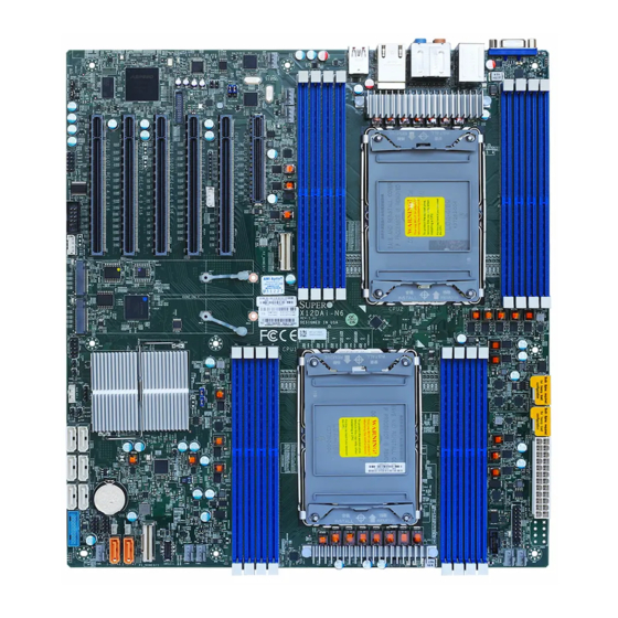
Introduction Congratulations on purchasing your computer motherboard from an industry leader. Supermicro motherboards are designed to provide you with the highest standards in quality and performance. In additon to the motherboard, several important parts that are included in the retail box are listed below. - Page 8 Super X12DAi-N6 User's Manual X12DAi-N6 Motherboard Image Note: All graphics shown in this manual were based upon the latest PCB revision available at the time of publication of the manual. The motherboard you received may or may not look exactly the same as the graphics shown in this manual.
- Page 9 X12DAi-N JM2_1 BAR CODE REV:1.01 DESIGNED IN USA MH15 MH16 JRK1 CMOS CLEAR JBT1 JNVME1 JSD1 JSD2 JPI2C1 CPU1 JUSB31_I1 FAN2 USB7(3.1) FAN1 FANA FAN4 FAN3 I-SATA6 I-SATA7 X12DAi-N6 Motherboard Layout Note: Components not documented are for internal testing only.
- Page 10 Super X12DAi-N6 User's Manual Quick Reference FAN7 FAN5 JSPDIF_OUT1 JLAN1 JSPDIF_IN1 JPL1 JVGA JAUDIO1 JPL2 LEDM1 JUSBA JUSB1 FAN6 JNCSI LAN/1/2 USB4(3.1) USB0/1/2/3(3.0) HEARTBEAT JVGA LEDM1 JUSBA JAUDIO1 JNCSI JUSB1 JLAN1 JPRG1 P2-DIMMF1 JPCIE1 JPCIE2 JPCIE3 JPCIE4 JPCIE5 JPCIE6 JPCIE1...
- Page 11 Power System Management Bus (SMB) I C header JPRG1 Complex-Programmable Logical Device (CPLD) header Note: For details on how to configure Network Interface Card (NIC) settings, please refer to the Network Interface Card Configuration User's Guide posted on our website under the link: http://www.supermicro.com/support/manuals/.
- Page 12 Super X12DAi-N6 User's Manual Connector Description JPWR1, JPWR2, JPWR4 8-pin power connectors JPWR3 24-pin ATX power connector JSPDIF_IN, JSPDIF_OUT SPDIF (Sony/Philips Digital Interconnect Format) Audio In/Out connectors JTPM1 Trusted Platform Module/Port 80 Connector JUSB1 (USB0/1/2/3) Back panel USB 3.0 ports JUSBA (USB4) Back panel USB 3.1 Type A port...
- Page 13 Six SATA 3.0 ports at 6Gb/s (I-SATA0-5 with RAID 0, 1, 5, 10) • SATA 3.0 • Two SATA 3.0 ports with Supermicro SATA DOM (SuperDOM) (I-SATA6-7) • • Audio One 7.1 High Definition (HD) Audio connector on the I/O back panel •...
- Page 14 Super X12DAi-N6 User's Manual Motherboard Features Peripheral Devices • One USB 3.1 port on the front/rear I/O panel • Six USB 3.0 ports on the front/rear I/O panel • One USB 3.2 Type-C Gen 2x1 port BIOS • 256Mb AMI BIOS SPI Flash BIOS ®...
- Page 15 Note 1: The CPU maximum thermal design power (TDP) is subject to chassis and heatsink cooling restrictions. For proper thermal management, please check the chas- sis and heatsink specifications for proper CPU TDP sizing. Note 2: For BMC configuration instructions, please refer to the Embedded BMC Con- figuration User's Guide available at http://www.supermicro.com/support/manuals/.
- Page 16 Super X12DAi-N6 User's Manual X12DAi-N6 CPU1-B1 CPU1-A1 CPU1-D1 CPU1-C1 CPU2-C1 CPU2-D1 CPU2-A1 CPU2-B1 PVCCIN_CPU1 12V_STBY PVCCIN_CPU1 12V_STBY VR13HC VR13HC 7+1 PHASE 7+1 PHASE 270W 270W 10.4/11.2G CPU1 CPU2 DDR4 DDR4 CPU1-F1 CPU1-E1 CPU1-H1 CPU1-G1 CPU2-G1 CPU2-H1 CPU2-E1 CPU2-F1 PECI:30 PECI:31...
-
Page 17: Processor And Chipset Overview
Intel C621A chipset, the X12DAi-N6 motherboard provides system performance, power efficiency, and feature sets optimized for high-performance workstation applications. With the support of the new Intel Microarchitecture, the X12DAi-N6 dramatically increases system performance for a multitude of workstation applications. -
Page 18: Special Features
Super X12DAi-N6 User's Manual 1.3 Special Features Recovery from AC Power Loss The Basic I/O System (BIOS) provides a setting that determines how the system will respond when AC power is lost and then restored to the system. You can choose for the system to remain powered off (in which case you must press the power switch to turn it back on), or for it to automatically return to the power-on state. -
Page 19: Acpi Features
It is even more important for processors that have high CPU clock rates where noisy power transmission is present. The X12DAi-N6 motherboard accommodates a 24-pin ATX power supply. Although most power supplies generally meet the specifications required by the CPU, some are inadequate. -
Page 20: Intel® Optane™ Persistent Memory (Pmem) 200 Series Overview
Super X12DAi-N6 User's Manual 1.8 Intel® Optane™ Persistent Memory (PMem) 200 Series Overview The 3rd Gen Intel Xeon Scalable support Intel Optane PMem 200 Series memory. Intel Optane PMem offers higher capacities than the traditional DDR4 modules. It also provides increased storage capabilities due to data persistence in a DDR4 form factor for higher performance computing platforms with flexible configuration options. -
Page 21: Chapter 2 Installation
Chapter 2: Installation Chapter 2 Installation 2.1 Static-Sensitive Devices Electrostatic Discharge (ESD) can damage electronic com ponents. To avoid damaging your system board, it is important to handle it very carefully. The following measures are generally sufficient to protect your equipment from ESD. Precautions •... -
Page 22: Processor And Heatsink Installation
Thermal grease is pre-applied on a new heatsink. No additional thermal grease is needed. • Refer to the Supermicro website for updates on processor and memory support. • All graphics in this manual are for illustrations only. Your components may look different. - Page 23 Chapter 2: Installation 1. The 3rd Gen Intel Xeon Scalable Processor = Cutout = Pin 1 = CPU Key Processor Top View...
- Page 24 Super X12DAi-N6 User's Manual 2. The Processor Carrier Carrier Top View = Cutout = Pin 1 = CPU Key Carrier Bottom View...
- Page 25 Chapter 2: Installation 3. Heatsink Note: Exercise extreme care when handling the heatsink. Pay attention to the edges of heatsink fins which can be sharp! To avoid damaging the heatsink, please do not apply excessive force on the fins when handling the heatsink.
- Page 26 Super X12DAi-N6 User's Manual Overview of the CPU Socket The CPU socket is protected by a plastic protective cover. Plastic Protective Cover CPU Socket...
- Page 27 Chapter 2: Installation Overview of the Processor Carrier Assembly The processor carrier assembly contains a 3rd Gen Intel Xeon Scalable processor and a processor carrier. Carefully follow the instructions given in the installation section to place a processor into the carrier to create a processor carrier. 1.
- Page 28 Super X12DAi-N6 User's Manual Overview of the Processor Heatsink Module The Processor Heatsink Module (PHM) contains a heatsink, a processor carrier, and the 3rd Gen Intel Xeon Scalable Processor 1. Heatsink 2. Processor Carrier 3. The 3rd Gen Intel Xeon Scalable Processor...
- Page 29 Chapter 2: Installation Creating the Processor Carrier Assembly The processor carrier assembly contains a 3rd Gen Intel Xeon Scalable processor and a processor carrier. To create the processor carrier assembly, please follow the steps below: Note: Before installation, be sure to follow the instructions given on Page 1 and Page 2 of this chapter to properly prepare yourself for installation.
- Page 30 Super X12DAi-N6 User's Manual 3. Locate the lever on the CPU socket and press the lever down as shown below.Using Lever 4. Using Pin 1 as a guide, carefully align the CPU keys (A and B) on the processor against the CPU keys on the carrier (a and b) as shown in the drawing below.
- Page 31 Chapter 2: Installation 6. After the processor is placed inside the carrier, examine the four sides of the processor, making sure that the processor is properly seated on the carrier. Processor Carrier Processor Carrier Assembly Assembly (bottom view) (Top View)
- Page 32 Super X12DAi-N6 User's Manual Creating the Processor Heatsink Module (PHM) After creating the processor carrier assembly, please follow the instructions below to mount the processor carrier into the heatsink to form the processor heatsink module (PHM). Note: If this is a new heatsink, the thermal grease has been pre-applied on the un- derside.
- Page 33 Chapter 2: Installation Preparing the CPU Socket for Installation This motherboard comes with a plastic protective cover installed on the CPU socket. Remove it from the socket to install the Processor Heatsink Module (PHM). Gently pull up one corner of the plastic protective cover to remove it. 1.
- Page 34 Super X12DAi-N6 User's Manual Preparing to Install the Processor Heatsink Module (PHM) into the CPU Socket After assembling the Processor Heatsink Module (PHM), you are ready to install it into the CPU socket. To ensure the proper installation, please follow the procedures below: 1.
- Page 35 Chapter 2: Installation Installing the Processor Heatsink Module (PHM) 1. Align peek nut "A", which is next to the triangle (Pin 1) on the heatsink, against threaded fastener "a" on the CPU socket. Then align peek nuts "B", "C", and "D" on the heatsink against threaded fasteners "b", "c", and "d"...
- Page 36 Super X12DAi-N6 User's Manual 4. With a T30-bit screwdriver, tighten all peek nuts in the sequence of "A", "B", "C", and "D" with even pressure. To avoid damaging the processor or socket, do not use a force greater than 12 lbf-in when tightening the screws.
- Page 37 Chapter 2: Installation Removing the Processor Heatsink Module from the CPU Socket Before removing the processor heatsink module (PHM) from the motherboard, unplug the AC power cord from all power supplies after shutting down the system. Then follow the steps below: 1.
- Page 38 Super X12DAi-N6 User's Manual Removing the Processor Carrier Assembly from the Processor Heatsink Module (PHM) To remove the processor carrier assembly from the PHM, please follow the steps below: 1. Detach four plastic clips (marked a, b, c, and d) on the processor carrier assembly from the four corners of heatsink (marked A, B, C, and D) in the drawings below.
- Page 39 Chapter 2: Installation Removing the Processor from the Processor Carrier Assembly Once you have removed the processor carrier assembly from the PHM, you are ready to remove the processor from the processor carrier by following the steps below. 1. Unlock the lever from its locking position and push the lever upwards to disengage the processor from the processor carrier as shown in the right drawing below.
-
Page 40: Motherboard Installation
Super X12DAi-N6 User's Manual 2.3 Motherboard Installation All motherboards have standard mounting holes to fit different types of chassis. Make sure that the locations of all the mounting holes for both the motherboard and the chassis match. Although a chassis may have both plastic and metal mounting fasteners, metal ones are highly recommended because they ground the motherboard to the chassis. - Page 41 Chapter 2: Installation Installing the Motherboard 1. Install the I/O shield into the back of the chassis, if applicable. 2. Locate the mounting holes on the motherboard. See the previous page for the location. 3. Locate the matching mounting holes on the chassis. Align the mounting holes on the motherboard against the mounting holes on the chassis.
-
Page 42: Memory Support And Installation
Memory Support The X12DAi-N6 supports up to 4TB 3DS LRDIMM/LRDIMM/3DS RDIMM/RDIMM DDR4 (288-pin) ECC memory with speeds of 3200/2933/2666 MHz in 16 memory slots and up to 4TB Intel Optane PMem 200 Series with speeds of up to 3200 MHz. (See the notes below.) Note 1: Intel®... - Page 43 2 CPUs & 14 DIMMs CPU1: P1-DIMMA1/P1-DIMME1/P1-DIMMC1/P1-DIMMG1/P1-DIMMB1/P1-DIMMF1/P1-DIMMD1/P1-DIMMH1 CPU2: P2-DIMMA1/P2-DIMME1/P2-DIMMC1/P2-DIMMG1/P2-DIMMB1/P2-DIMMF1 2 CPUs & 16 DIMMs (Note) CPU1: P1-DIMMA1/P1-DIMME1/P1-DIMMC1/P1-DIMMG1/P1-DIMMB1/P1-DIMMF1/P1-DIMMD1/P1-DIMMH1 CPU2: P2-DIMMA1/P2-DIMME1/P2-DIMMC1/P2-DIMMG1/P2-DIMMB1/P2-DIMMF1/P2-DIMMD1/P2-DIMMH1 Note: This memory configuration is recommended by Supermicro for optimal memory performance. Please use this configuration to maximize your memory performance.
- Page 44 Super X12DAi-N6 User's Manual Intel Optane PMem 200 Series Memory Population Table Note: Intel® Optane™ Persistent Memory (PMem) 200 Series is supported by the 3rd Gen Intel Xeon Scalable (83xx/63xx/53xx/4314 Series) Processors. PMem 200 Series Population Table for X12DP 16-DIMM Motherboards (within 1 CPU socket)
- Page 45 Chapter 2: Installation DIMM Installation LAN/1/2 USB4(3.1) USB0/1/2/3(3.0) HEARTBEAT JVGA LEDM1 JUSBA JAUDIO1 JNCSI JUSB1 JLAN1 1. Insert the desired number of DIMMs into the JPCIE1 JPCIE2 JPCIE3 JPCIE4 JPCIE5 JPCIE6 memory slots based on the recommended DIMM population table on pg. 43. COM1 JNVI2C JNVME2...
- Page 46 Super X12DAi-N6 User's Manual DIMM Removal Press both release tabs on the ends of the DIMM module to unlock it. Once the DIMM module is loosened, remove it from the memory slot. Warning! Please do not use excessive force when pressing the release tabs on the ends of the DIMM socket to avoid causing any damage to the DIMM module or the DIMM socket.
-
Page 47: Rear I/O Ports
Chapter 2: Installation 2.5 Rear I/O Ports See Figure 2-1 below for the locations and descriptions of the various I/O ports on the rear of the motherboard. LAN/1/2 USB4(3.1) USB0/1/2/3(3.0) HEARTBEAT JVGA LEDM1 JUSBA JAUDIO1 JNCSI JUSB1 JLAN1 JPCIE1 JPCIE2 JPCIE3 JPCIE4 JPCIE5... - Page 48 Super X12DAi-N6 User's Manual VGA Port A video (VGA) port is located next to LAN2 on the I/O back panel. Refer to the board layout below for the location. 7.1 HD (High-Definition) Audio This motherboard features a 7.1 Channel High-Definition Audio (HDA) codec that provides 8 DAC channels.
- Page 49 Chapter 2: Installation COM Ports A single COM connection (COM1) are located on the motherboard. COM1 is located next to PCIe slot 1 (JPCIE1). Refer to the motherboard layout below for the locations of COM1. COM Port Pin Definitions Pin# Definition Pin# Definition...
- Page 50 Two Gigabit Ethernet ports (LAN1, LAN2) are located on the I/O back panel. These Ethernet ports support 1GbE LAN connections on the X12DAi-N6. Both LAN ports accept RJ45 cables. Please refer to the LED Indicator section for LAN LED information.
- Page 51 Chapter 2: Installation Universal Serial Bus (USB) Ports There are four USB 3.0 ports (USB0/1/2/3) and one USB 3.1 ports (USB4) located on the I/O back panel. The motherboard also has a front-accessible USB 3.0 header that provides two USB 3.0 connections (USB5/6) and a front-accessible USB 3.2 Gen 2x1 Type C header (USB7).
-
Page 52: Front Control Panel
JF1 contains header pins for various buttons and indicators that are normally located on a control panel at the front of the chassis. These connectors are designed specifically for use with Supermicro chassis. See the figure below for the descriptions of the front control panel buttons and LED indicators. - Page 53 Chapter 2: Installation Front Control Panel LEDs Front Control Panel (JF1) LED Indicators Event Power (LED1) HDD (LED2) LAN (LED3/4) UID (LED5) Information (LED5) Power Fail (LED6) Power On Solid On HDD Activity Blinking NIC Activity Blinking Overheat Solid On Fan Fail Blinking @1Hz Power Fail...
- Page 54 Super X12DAi-N6 User's Manual Power On and BMC/BIOS Status LED Button The Power On and BMC/BIOS Status LED button is located on pins 1 and 2 of JF1. Momentarily contacting both pins will power on/off the system or display BMC/BIOS status.
- Page 55 Chapter 2: Installation Power Fail LED The Power Fail LED connection is located on pins 5 and 6 of JF1. When this LED turns solid red, it indicates a power failure. Refer to the table below for pin definitions. Power Fail LED Pin Definitions (JF1) Pin# Definition...
- Page 56 Super X12DAi-N6 User's Manual NIC1/NIC2 (LAN1/LAN2) The NIC (Network Interface Controller) LED connection for LAN Port 1 is located on pins 11 and 12 of JF1, and LAN Port 2 is on pins 9 and 10. Refer to the tables below for pin definitions.
- Page 57 Chapter 2: Installation FP Power LED The Front Panel Power LED connection is located on pins 15 and 16 of JF1. Refer to the table below for pin definitions. FP Power LED Pin Definitions (JF1) Pins Definition 3.3V FP PWR LED NMI Button The non-maskable interrupt (NMI) button header is located on pins 19 and 20 of JF1.
-
Page 58: Connectors
Super X12DAi-N6 User's Manual 2.7 Connectors Power Connections ATX Power Supply Connector The 24-pin power supply connector (JPWR3) meets the ATX SSI EPS 12V specification. You must also connect the 8-pin (JPWR1/JPWR2/JPWR4) processor power connectors to the power supply. Refer to the next page for more information on JPWR1/JPWR2/JPWR4. - Page 59 Chapter 2: Installation 8-Pin Power Connectors JPWR1, JPWR2, and JPWR4 are 8-pin 12V DC power input for the CPU that must be connected to the power supply. Refer to the table below for pin definitions. 8-pin Power Pin Definitions Pin# Definition 1 - 4 Ground...
- Page 60 Super X12DAi-N6 User's Manual Headers Fan Headers There are eight 4-pin fan headers (FAN1 ~ FAN7, FANA) on the motherboard. All these 4-pin fan headers are backwards compatible with the traditional 3-pin fan connectors. However, fan speed control is available for 4-pin fans only by Thermal Management via the BMC interface.
- Page 61 Chapter 2: Installation SGPIO Headers There are two Serial_Link General Purpose Input/Output (I-SGPIO1 and I-SGPIO2) headers located on the motherboard. I-SGPIO is used for communicate with the enclosure management chip on the backplane. Refer to the tables below for pin definitions. SGPIO Header Pin Definitions Pin#...
- Page 62 Super X12DAi-N6 User's Manual TPM/Port 80 Header A Trusted Platform Module (TPM)/Port 80 header is located at JTPM1 to provide TPM support and Port 80 connection. Use this header to enhance system performance and data security. Refer to the table below for pin definitions. Please go to the following link for more information on the TPM: http://www.supermicro.com/manuals/other/TPM.pdf.
- Page 63 Chapter 2: Installation Power SMB (I C) Header The Power System Management Bus (I C) connector (JPI2C1) monitors the power supply, fan, and system temperatures. Refer to the table below for pin definitions. Power SMB Header Pin Definitions Pin# Definition Clock Data PMBUS_Alert...
- Page 64 C) header (JNVI2C), used for PCIe SMBus clock and data connections, provide hot-plug support via a dedicated SMBus interface. This feature is only available for a Supermicro complete system with an SMCI-proprietary NVMe add-on card and cable installed. See the table below for pin definitions.
- Page 65 Chapter 2: Installation Chassis Intrusion A Chassis Intrusion header is located at JL1 on the motherboard. Attach the appropriate cable from the chassis to inform you of a chassis intrusion when the chassis is opened. Refer to the table below for pin definitions. Chassis Intrusion Pin Definitions Pin#...
- Page 66 Super X12DAi-N6 User's Manual Speaker Header (Optional for an External Speaker/Buzzer) A speaker header, located at JD1, can be used in conjunction with an external speaker (optional). Use an appropriate cable to connect this header to an external speaker or buzzer for support of BIOS beep codes and system alarms.
- Page 67 M.2 Slot The X12DAi-N6 motherboard has two M.2 slots (JM2_1 and JM2_2). M.2 was formerly known as Next Generation Form Factor (NGFF) and serves to replace mini PCIe. M.2 allows for a variety of card sizes, increased functionality, and a spatial efficiency. The M.2 socket on the motherboard supports PCIe 4.0 x4 (32 Gb/s) SSD cards in the 2280 and 22110 form factors.
- Page 68 Super X12DAi-N6 User's Manual VROC RAID Key Header A VROC RAID Key header is located at JRK1 on the motherboard. Install a VROC RAID Key on JRK1 for NVMe RAID support as shown in the illustration below. Please refer to the layout below for the location of JRK1.
- Page 69 Chapter 2: Installation T-SGPIO 1/2/3 Headers The T-SGPIO (Serial General Purpose Input/Output) headers are used for the onboard SATA devices to communicate with the enclosure management chip on the backplane. See the table below for more information. T-SGPIO 1/2/3 Headers T-SGPIO 1/2/3 Headers Pin Definitions Corresponding SATA Device Support...
-
Page 70: Jumper Settings
Super X12DAi-N6 User's Manual 2.8 Jumper Settings How Jumpers Work To modify the operation of the motherboard, jumpers can be used to choose between optional settings. Jumpers create shorts between two pins to change the function of the connector. Pin 1 is identified with a square solder pad on the printed circuit board. See the diagram below for an example of jumping pins 1 and 2. - Page 71 Chapter 2: Installation Watchdog Watchdog (JWD1) is a system monitor that can reboot the system when a software application hangs. Close pins 1-2 to reset the system if an application hangs. Close pins 2-3 to generate a non-maskable interrupt (NMI) signal for the application that hangs. Refer to the table below for jumper settings.
- Page 72 Super X12DAi-N6 User's Manual Management Engine (ME) Recovery Use jumper JPME1 to select ME Firmware Recovery mode, which will limit resource allocation for essential system operation only in order to maintain normal power operation and management. In the single operation mode, online upgrade will be available via Recovery mode.
-
Page 73: Led Indicators
Chapter 2: Installation 2.9 LED Indicators LAN LEDs Two LAN ports (LAN 1 and LAN 2) are located on the I/O back panel of the motherboard. Each Ethernet LAN port has two LEDs. The solid green LED indicates activity, while the other Link LED may be green, amber, or off to indicate the speed of the connection. - Page 74 Super X12DAi-N6 User's Manual M.2 LED Two M.2 LEDs are located at LE4 and LE7 on the motherboard. When the LED is blinking, M.2 functions normally. Refer to the table below for more information. M.2 LED State LED Color Definition...
- Page 75 Chapter 2: Installation Onboard Power LED The Onboard Power LED is located at PWRLED on the motherboard. When this LED is on, the system is on. Be sure to turn off the system and unplug the power cord before removing or installing components.
-
Page 76: Chapter 3 Troubleshooting
Super X12DAi-N6 User's Manual Chapter 3 Troubleshooting 3.1 Troubleshooting Procedures Use the following procedures to troubleshoot your system. If you have followed all of the procedures below and still need assistance, refer to the ‘Technical Support Procedures’ and/ or ‘Returning Merchandise for Service’ section(s) in this chapter. Always disconnect the AC power cord before adding, changing or installing any non hot-swap hardware components. - Page 77 Chapter 3: Troubleshooting No Video 1. If the power is on, but you have no video, remove all add-on cards and cables. 2. Remove all memory modules and turn on the system (if the alarm is on, check the specs of memory modules, reset the memory or try a different one). System Boot Failure If the system does not display POST (Power-On-Self-Test) or does not respond after the power is turned on, check the following:...
- Page 78 Super X12DAi-N6 User's Manual When the System Becomes Unstable A. If the system becomes unstable during or after OS installation, check the following: 1. CPU/BIOS support: Make sure that your CPU is supported and that you have the latest BIOS installed in your system.
-
Page 79: Technical Support Procedures
Before contacting Technical Support, please take the following steps. Also, please note that as a motherboard manufacturer, Supermicro also sells motherboards through its channels, so it is best to first check with your distributor or reseller for troubleshooting services. They should know of any possible problems with the specific system configuration that was sold to you. -
Page 80: Frequently Asked Questions
BIOS revision to make sure that it is newer than your BIOS before downloading. Note1: The SPI BIOS chip used on this motherboard cannot be removed. Send your motherboard back to our RMA Department at Supermicro for repair. Note2: For BIOS Update and Recovery instructions, please refer to the Firmware Update and Recovery Instructions for Supermicro's X12 Motherboards User's Guide posted at http://www.supermicro.com/support/manuals/. -
Page 81: Battery Removal And Installation
Chapter 3: Troubleshooting 3.4 Battery Removal and Installation Battery Removal To remove the onboard battery, follow the steps below: 1. Power off your system and unplug your power cable. 2. Locate the onboard battery as shown below. 3. Using a tool such as a pen or a small screwdriver, push the battery lock outwards to unlock it. -
Page 82: Returning Merchandise For Service
Super X12DAi-N6 User's Manual 3.5 Returning Merchandise for Service A receipt or copy of your invoice marked with the date of purchase is required before any warranty service will be rendered. You can obtain service by calling your vendor for a Returned Merchandise Authorization (RMA) number. -
Page 83: Chapter 4 Uefi Bios
Chapter 4: BIOS Chapter 4 UEFI BIOS 4.1 Introduction This chapter describes the AMIBIOS™ Setup utility for the motherboard. The BIOS is stored on a chip and can be easily upgraded using a flash program. Note: Due to periodic changes to the BIOS, some settings may have been added or deleted and might not yet be recorded in this manual. -
Page 84: Main Setup
Super X12DAi-N6 User's Manual 4.2 Main Setup When you first enter the AMI BIOS setup utility, you will enter the Main setup screen. You can always return to the Main setup screen by selecting the Main tab on the top of the screen. - Page 85 Chapter 4: BIOS CPLD Version This item displays the Complex Programmable Logic Device version. Memory Information Total Memory This item displays the total size of memory available in the system.
-
Page 86: Advanced Setup Configurations
Super X12DAi-N6 User's Manual 4.3 Advanced Setup Configurations Use the arrow keys to select the Advanced menu and press <Enter> to access the submenu items: Warning: Take caution when changing the Advanced settings. An incorrect value, a very high DRAM frequency, or an incorrect DRAM timing setting may make the system unstable. When this occurs, revert to default manufacturer settings. - Page 87 Chapter 4: BIOS Bootup NumLock State Use this feature to set the Power-on state for the <Numlock> key. The options are On and Off. Wait For "F1" If Error Use this feature to force the system to wait until the "F1" key is pressed if an error occurs. The options are Disabled and Enabled.
- Page 88 Super X12DAi-N6 User's Manual Power Configuration Watch Dog Function Select Enabled to allow the Watch Dog timer to reboot the system when it is inactive for more than 5 minutes. The options are Enabled and Disabled. If this feature is set to Enabled, the following feature will display: Watch Dog Action (Available when "Watch Dog Function"...
- Page 89 Chapter 4: BIOS CPU Configuration The following CPU information will display: • Processor BSP Revision • Processor Socket • Processor ID • Processor Frequency • Processor Max Ratio • Processor Min Ratio • Microcode Revision • L1 Cache RAM •...
- Page 90 Super X12DAi-N6 User's Manual CPU1 Core Disable Bitmap/CPU2 Core Disable Bitmap The following features will display: Available Bitmap: The available Bitmap will displayed. Core Disable Bitmap (Hex) Enter 0 to enable all CPU cores. Enter FFFFFFFFFFF to disable all CPU cores. Please note that at least one core per CPU must be enabled.
- Page 91 Chapter 4: BIOS Select Enable to enable the Intel Vanderpool Technology for Virtualization platform support, which will allow multiple operating systems to run simultaneously on the same computer to maximize system resources for performance enhancement. The options are Enable and Disable.
- Page 92 Super X12DAi-N6 User's Manual ---------------------------------------------------------------- Software Guard Extension (SGX) -------------------------------------------------------------- Note: For SGX to work properly, please use the CPUs that support this feature and be sure to install one CPU per channel. SGX Factory Reset (Available when TME-MT is set to Enabled and the SGX feature is supported by the CPU used in the system) Select Enabled to reset the factory default setting for SGX (Software Guard Extension).
- Page 93 Chapter 4: BIOS Advanced Power Management Configuration Power Technology Select Energy Effiency to support power-saving mode. Select Custom to customize system power settings. Select Disable to disable power-saving settings. The options are Disable, Energy Efficient, and Custom. If the feature above is set to Custom, the following features will become available for configuration: Power Performance Tuning This feature allows the user to select whether the BIOS or Operating System chooses energy performance bias tuning.
- Page 94 Super X12DAi-N6 User's Manual CPU P State Control (Available when "Power Technology" is set to Custom) SpeedStep (Pstates) EIST (Enhanced Intel SpeedStep Technology) allows the system to automatically adjust processor voltage and core frequency in an effort to reduce power consumption and heat dissipation.
- Page 95 Chapter 4: BIOS CPU C State Control Enable Monitor MWAIT Select Enable to support Monitor and Mwait, which are two instructions in Streaming SIMD Extension 3 (SSE3), to improve synchronization between multiple threads for CPU performance enhancement. The options are Enable, and Disable. CPU C6 Report (Available when "Autonomous Core C-State"...
- Page 96 Super X12DAi-N6 User's Manual Chipset Configuration Warning: Setting the wrong values in the following features may cause the system to malfunc- tion. North Bridge This feature allows the user to configure Intel North Bridge parameters. Uncore Configuration ...
- Page 97 Chapter 4: BIOS Degrade Precedence Use this feature to select the degrading precedence option for Ultra Path Interconnect (UPI) connections. Select Topology Precedent to degrade UPI features if the system options are in conflict. Select Feature Precedent to degrade UPI topology if system options are in conflict.
- Page 98 Super X12DAi-N6 User's Manual XPT Remote Prefetch Select Enable to support XPT (Extended Prediction Table) Remote Prefetch which will allow an LLC request to be duplicated and sent to an appropriate memory controller in a remote machine based on the recent LLC history to reduce latency. The options are Enable, Disable, and Auto.
- Page 99 Chapter 4: BIOS Stale AtoS (A to S) The in-memory directory has three states: I, A, and S states. The I (-invalid) state indicates that the data is clean and does not exist in the cache of any other sockets. The A (-snoop All) state indicates that the data may exist in another socket in an exclusive or modified state.
- Page 100 Super X12DAi-N6 User's Manual STEP(Samsung TestBIOS & Enchanced PPR) DRAM Test Select Enable to enable Samsung TestBIOS & Enchanced PPR funtion. The options are Enable and Disable. Operation Mode(Available when "STEP DRAM Test" is set to Enable) Use this feature to set the operation mode for STEP DRAM Test. The options are Test Only and Test and Repair.
- Page 101 Chapter 4: BIOS Legacy ADR Mode (Available when "Enabled ADR" is set to Enable) Select Enable to support Legacy ADR (Async DIMM Module Self-Refresh) mode to enhance memory performance. The options are Enable and Disable. Erase-Arm NVDIMMs (Available when "Enabled ADR" is set to Enable, and when NVDIMMs are detected/installed in the system) If this feature is set to Enable, the function that "arms"...
- Page 102 Super X12DAi-N6 User's Manual Memory RAS (Reliability_Availability_Serviceability) Configuration Enable Pcode WA (Workaround) for SAI (Security Attribute of the Initiator) PG (Policy Group) Pcode, a register transfer language designed for reverse engineering, translates individual processor instructions into a sequence of Pcode operations in order to facilitate the construction of data-flow graphs and dissembling of processor instructions for machine application.
- Page 103 Chapter 4: BIOS Correctable Error Threshold This feature allows the user to enter the threshold value for correctable memory errors. The default setting is 512. Partial Cache Line Sparing PCLS Select Enabled to support partial cache line sparing, which will allow partial of data contained in a cache line to be copied in the cache memory for safe-keeping/data security.
- Page 104 Super X12DAi-N6 User's Manual IOU4 (IIO PCIe Port 5) Use this feature to configure the PCIe Bifurcation setting for a PCIe port specified by the user. The options are x4x4x4x4, x4x4x8, x8x4x4, x8x8, x16, and Auto. IOAT Configuration Disable TPH TPH (TLP Processing Hint) is used for data-tagging with a destination ID and a few important attributes.
- Page 105 Chapter 4: BIOS Intel® VMD Technology This section describes the configuration settings for the Intel VMD Technology. Note 1. After you’ve enabled VMD in the BIOS on a PCIe slot, this PCIe slot will be dedicated for VMD use only, and it will no longer support any PCIe device. To re-activate this slot for PCIe use, please disable VMD in the BIOS.
- Page 106 Super X12DAi-N6 User's Manual VMD Config for IOU 3 Enable/Disable VMD Select Enable to enable Intel Volume Management Device Technology support for the root port specified by the user. The options are Enable and Disable. *If Enable/Disable VMD is set to Enable to a port specified by the user, the following items will display for the port selected.
- Page 107 Chapter 4: BIOS VMD Config for IOU 1 Enable/Disable VMD Select Enable to enable Intel Volume Management Device Technology support for the root port specified by the user. The options are Enable and Disable. *If Enable/Disable VMD is set to Enable to a port specified by the user, the following items will display for the port selected. VMD Port 2A/2B/2C/2D (Available for onboard NVMe ports only) Select Enable to enable Intel Volume Management Device Technology support for the root port.
- Page 108 Super X12DAi-N6 User's Manual IIO eDPC (Enhanced Downstream Port Containment) Support Use this feature to configure the setting for IIO Enhanced Downstream Port Containment (eDPC) support for your system in an effort to improve the error containment capacity within the PCIe subsystem when an uncorrected error is detected either at the root port or at the switch downstream port.
- Page 109 Chapter 4: BIOS South Bridge The following South Bridge information will display: • USB Module Version • USB Devices Legacy USB Support Select Enabled to support onboard legacy USB devices. Select Auto to disable legacy support if there are no legacy USB devices present. Select Disable to have all USB devices available for EFI applications only.
- Page 110 Super X12DAi-N6 User's Manual PCIe PLL SSC Select Enabled for PCH PCIe Spread Spectrum Clocking support, which will allow the BIOS to monitor and attempt to reduce the level of electromagnetic interference caused by the components whenever needed. The options are Enabled and Disabled.
- Page 111 Chapter 4: BIOS SATA Configuration SATA Controller This feature enables or disables the onboard SATA controller supported by the Intel PCH chip. The options are Enable and Disable. Configure SATA as (Available when "SATA Controller" is set to Enable) Select AHCI to configure a SATA drive specified by the user as an AHCI drive.
- Page 112 Super X12DAi-N6 User's Manual SATA RAID Option ROM/UEFI Driver (Available when "Configure SATA as" is set to RAID) Select EFI to load the EFI driver for system boot. Select Legacy to load a legacy driver for system boot. The options are Disable, EFI, and Legacy.
- Page 113 Chapter 4: BIOS PCIe/PCI/PnP Configuration The following PCI information will be displayed: • PCI Bus Driver Version Above 4G Decoding (Available if the system supports 64-bit PCI decoding) Select Enabled to decode a PCI device that supports 64-bit in the space above 4G Address. The options are Enabled and Disabled.
- Page 114 Super X12DAi-N6 User's Manual MMIO High Base Use this feature to select the base memory size according to memory-address mapping for the IO hub. The options are 40T, 32T, 24T, 16T, 4T, 2T, 1T, 512 G. MMIO High Granularity Size Use this feature to select the high memory size according to memory-address mapping for the IO hub.
- Page 115 Chapter 4: BIOS Onboard P1_NVME 0 Option ROM/Onboard P1_NVME 1 Option ROM/ Onboard P2_ NVME 0 Option ROM/Onboard P2_NVME 1 Option ROM Select EFI to allow the user to boot the computer using an EFI (Extensible Firmware Interface) device installed on the NVMe connector specified by the user. Select Legacy to boot the computer using a legacy device installed on the NVME connector specified by the user.
- Page 116 Super X12DAi-N6 User's Manual Serial Port 1 Configuration Serial Port Select Enabled to enable Serial Port 1. The options are Enabled and Disabled. Device Settings (Available when "Serial Port 1" is set to Enabled) This feature displays the base I/O port address and the Interrupt Request address of Serial Port 1.
- Page 117 Chapter 4: BIOS Serial Port Console Redirection COM1 Console Redirection Select Enabled to enable COM Port 1 for Console Redirection, which will allow a client machine to be connected to a host machine at a remote site for networking. The options are Enabled and Disabled.
- Page 118 Super X12DAi-N6 User's Manual Bits Per second Use this feature to set the transmission speed for a serial port used in Console Redirection. Make sure that the same speed is used in the host computer and the client computer. A lower transmission speed may be required for long and busy lines.
- Page 119 Chapter 4: BIOS Flow Control Use this feature to set the flow control for Console Redirection to prevent data loss caused by buffer overflow. Send a "Stop" signal to stop sending data when the receiving buffer is full. Send a "Start" signal to start sending data when the receiving buffer is empty. The options are None and Hardware RTS/CTS.
- Page 120 Super X12DAi-N6 User's Manual Bits Per second Use this feature to set the transmission speed for a serial port used in Console Redirection. Make sure that the same speed is used in the host computer and the client computer. A lower transmission speed may be required for long and busy lines.
- Page 121 Chapter 4: BIOS Flow Control Use this feature to set the flow control for Console Redirection to prevent data loss caused by buffer overflow. Send a "Stop" signal to stop sending data when the receiving buffer is full. Send a "Start" signal to start sending data when the receiving buffer is empty. The options are None and Hardware RTS/CTS.
- Page 122 Super X12DAi-N6 User's Manual Legacy Console Redirection Settings Legacy Console Redirection Port Use this feature to select the COM port to display redirection of Legacy OS and Legacy OPROM messages. The options are SOL and COM1. Legacy OS Redirection Resolution Use this feature to select the number of rows and columns used in Console Redirection for Legacy OS support.
- Page 123 Chapter 4: BIOS Bits Per Second This feature sets the transmission speed for a serial port used in Console Redirection. Make sure that the same speed is used in both host computer and the client computer. A lower transmission speed may be required for long and busy lines. The options are 9600, 19200, 57600, and 115200 (bits per second).
- Page 124 Super X12DAi-N6 User's Manual ACPI Settings Use this feature to configure Advanced Configuration and Power Interface (ACPI) power management settings for your system. NUMA Select Enabled to enable Non-Uniform Memory Access support to enhance system performance. The options are Enabled and Disabled.
- Page 125 Chapter 4: BIOS Trusted Computing (Available when a TPM device is installed and detected by the BIOS) When a TPM (Trusted-Platform Module) device is detected in your machine, the following information will display: • TPM 2.0 Device Found: • Firmware Version: •...
- Page 126 Super X12DAi-N6 User's Manual SHA-1 PCR Bank Select Enabled to enable SHA-1 PCR Bank support to enhance system integrity and data security. The options are Enabled and Disabled. SHA256 PCR Bank Select Enabled to enable SHA256 PCR Bank support to enhance system integrity and data security.
- Page 127 EV DFX (Device Function On-Hide) support when it is present in the BIOS for the system to work properly Note 2: For more information on TPM, please refer to the TPM manual at http://www. supermicro.com/manuals/other. Network Configuration Network Stack Select Enabled to enable PXE (Preboot Execution Environment) or UEFI (Unified Extensible Firmware Interface) for network stack support.
- Page 128 Super X12DAi-N6 User's Manual IPv4 PXE Support Select Enabled to enable IPv4 PXE boot support. If this feature is disabled, it will not create the IPv4 PXE boot option. The options are Disabled and Enabled. IPv4 HTTP Support Select Enabled to enable IPv4 HTTP boot support. If this feature is disabled, it will not create the IPv4 HTTP boot option.
- Page 129 Chapter 4: BIOS HTTP Boot Configuration HTTP Boot Policy Use this feature to select HTTP Boot Policy. The options are Apply to all LANs, Apply to each LAN, and Boot Priority #1 instantly. Instance of Priority 1 Use this feature to select the priority of the targeted LAN port. The default value is 1. Select IPv4 or IPv6 Use this feature to select Internet Protocol version for the targeted LAN port.
- Page 130 Super X12DAi-N6 User's Manual TLS Authentication Configuration This submenu allows the user to configure Transport Layer Security (TLS) settings. Server CA Configuration This feature allows the user to configure the client certificate that is to be used by the server.
- Page 131 Chapter 4: BIOS Discard Changes and Exit Select this feature to discard the changes you have made and exit from the system. Delete Certification If this feature is set to Enable, the certificate enrolled in the system will be deleted. The options are Enable and Disable.
- Page 132 Super X12DAi-N6 User's Manual Intel® I210 Gigabit Network Connection Firmware Image Properties The following information will be displayed: • Option ROM Version • Unique NVM/EEPROM ID • NVM Version NIC Configuration Link Speed This feature displays the connection speed of a LAN port specified by the user.
- Page 133 Chapter 4: BIOS • UEFI Driver • Adapter PBA • Device Name • Chip Type • PCI Device ID • PCI Address • Link Status • MAC Address • Virtual MAC Address...
- Page 134 Super X12DAi-N6 User's Manual VLAN Configuration Enter Configuration Menu Create New VLAN This feature allows the user to create a new VLAN. VLAN ID Use this feature to create a new LAN ID by using an existing VLAN or creating a new VLAN ID. Enter a valid value between 0 ~ 4094.
- Page 135 Chapter 4: BIOS IPv6 Network Configuration Enter Configuration Menu The following features will display: • Interface Name • Interface Type • MAC Address • Host Addresses • Route Table • Gateway Addresses • DNS Addresses Interface ID This feature displays the Interface ID used in the network. DAD (Duplicate Address Detection) Transmit Count This feature displays the DAD Transmit Count.
- Page 136 Super X12DAi-N6 User's Manual Policy Use this feature to select how the policy is to be configured. The options are Automatic and Manual. Save Changes and Exit. Select Yes to save the changes that you've made and exit from this submenu.
- Page 137 Chapter 4: BIOS IPv4 Network Configuration Configured Select Enabled to show whether the network address has been successfully configured or not. The options are Enabled and Disabled. *If this feature is set to Enabled, the following items will display. Enable DHCP Select Enabled to support Dynamic Host Configuration Protocol (DHCP) which will allow the BIOS to search for a DHCP server attached to the network and request the next available...
- Page 138 Super X12DAi-N6 User's Manual Intel® I210 Gigabit Network Connection Firmware Image Properties The following information will be displayed: • Option ROM Version • Unique NVM/EEPROM ID • NVM Version NIC Configuration Link Speed This feature displays the connection speed of a LAN port specified by the user.
- Page 139 Chapter 4: BIOS Blink LEDs This feature displays the number of blinking LED indicators of the LAN port specified by the user. The following information will be displayed as well: • UEFI Driver • Adapter PBA • Device Name • Chip Type •...
- Page 140 Super X12DAi-N6 User's Manual VLAN Configuration Enter Configuration Menu Create New VLAN This feature allows the user to create a new VLAN. VLAN ID Use this feature to create a new LAN ID by using an existing VLAN or creating a new VLAN ID. Enter a valid value between 0 ~ 4094.
- Page 141 Chapter 4: BIOS IPv6 Network Configuration Enter Configuration Menu The following features will display: • Interface Name • Interface Type • MAC Address • Host Addresses • Route Table • Gateway Addresses • DNS Addresses Interface ID This feature displays the Interface ID used in the network. DAD (Duplicate Address Detection) Transmit Count This feature displays the DAD Transmit Count.
- Page 142 Super X12DAi-N6 User's Manual Policy Use this feature to select how the policy is to be configured. The options are Automatic and Manual. Save Changes and Exit. Select Yes to save the changes that you've made and exit from this submenu.
- Page 143 Chapter 4: BIOS IPv4 Network Configuration Configured Select Enabled to show whether the network address has been successfully configured or not. The options are Enabled and Disabled. *If this feature is set to Enabled, the following items will display. Enable DHCP Select Enabled to support Dynamic Host Configuration Protocol (DHCP) which will allow the BIOS to search for a DHCP server attached to the network and request the next available...
- Page 144 Super X12DAi-N6 User's Manual Driver Health This feature displays the following driver health information:...
-
Page 145: Event Logs
Chapter 4: BIOS 4.4 Event Logs Use this feature to configure Event Log settings. Note: After you've made any changes on a setting below, please reboot the system for the changes you've made to take effect. Change SMBIOS Event Log Settings Enabling/Disabling Options SMBIOS Event Log Select Enabled to enable SMBIOS (System Management BIOS) Event Logging during system... - Page 146 Super X12DAi-N6 User's Manual When Log is Full Select Erase Immediately to immediately erase all errors in the SMBIOS event log when the event log is full. Select Do Nothing for the system to do nothing when the SMBIOS event log is full.
-
Page 147: Bmc
Chapter 4: BIOS 4.5 BMC Use this feature to configure Baseboard Management Controller (BMC) settings. BMC Firmware Revision This item indicates the BMC firmware revision used in your system. Status Of BMC (Baseboard Management Controller) This item indicates the status of the BMC firmware installed in your system. System Event Log Enabling/Disabling Options SEL Components... - Page 148 Super X12DAi-N6 User's Manual When SEL is Full This feature allows the user to decide what the BIOS should do when the system event log is full. Select Erase Immediately to erase all events in the log when the system event log is full.
- Page 149 Chapter 4: BIOS Gateway IP Address This item displays the Gateway IP address for this computer. This should be in decimal and in dotted quad form (i.e., 172.31.0.1). VLAN This item displays the virtual LAN settings. The options are Disable and Enable. Configure IPV6 Support This section displays configuration features for IPV6 support.
-
Page 150: Security
Super X12DAi-N6 User's Manual 4.6 Security This menu allows the user to configure the following security settings for the system. Administrator Password This feature indicates if an administrator password has been installed. It also allows the user to set the administrator password which is required to enter the BIOS setup utility. The length of the password should be from 3 characters to 20 characters long. - Page 151 Chapter 4: BIOS SMCI Security Erase Configuration This section allows the user to configure the SMCI-proprietary Security Erase settings. When this section is selected, the following features will display: • HDD Name: This feature displays the name of the HDD/SATA drive that is connected to the SMCI Security Erase Configuration submenu.
- Page 152 Super X12DAi-N6 User's Manual Secure Boot Note: For detailed instructions on how to configure Secure Boot settings, please refer to the Secure Boot Configuration User's Guide posted on the web page under the link: http://www.supermicro.com/support/manuals/. When you select this submenu and press the <Enter> key, the following items will display: •...
- Page 153 Chapter 4: BIOS Restore Factory Keys Select Yes to restore manufacture default keys used to ensure system security. The options are Yes and No. Reset to Setup Mode This feature resets the system to Setup Mode. The options are Yes and No. Enter Audit Mode ...
- Page 154 Super X12DAi-N6 User's Manual Restore Factory Keys Select Yes to restore manufacturer default keys used to ensure system security. The options are Yes and No. Reset to Setup Mode This feature resets the system to Setup Mode. Export Secure Boot Variables ...
- Page 155 Chapter 4: BIOS Authorized Signatures Use this feature to enter and configure a set of values to be used as Authorized Signatures for the system. These values also indicate the sizes, keys numbers, and the sources of the authorized signatures. Select Update to update your "Authorized Signatures". Select Append to append your "Authorized Signatures".
-
Page 156: Boot
Super X12DAi-N6 User's Manual 4.7 Boot Use this feature to configure Boot Settings: Boot Mode Select Use this feature to select the type of devices from which the system will boot. The options are LEGACY, UEFI (Unified Extensible Firmware Interface), and DUAL. - Page 157 Chapter 4: BIOS Delete Boot Option This feature allows the user to select a boot device to delete from the boot priority list. Delete Boot Option This feature allows the user to remove an EFI boot option from the boot priority list. ...
-
Page 158: Save & Exit
Super X12DAi-N6 User's Manual 4.8 Save & Exit Select the Save & Exit menu from the BIOS setup screen to configure the settings below. Save Options Discard Changes and Exit Select this option to exit from the BIOS setup utility without making any permanent changes to the system configuration and reboot the computer. - Page 159 Chapter 4: BIOS Default Options Restore Optimized Defaults To set this feature, select Restore Default Values from the Exit menu and press <Enter> to load manufacturer default settings which are intended for maximum system performance but not for maximum stability. Save As User Defaults To set this feature, select this feature and press <Enter>...
-
Page 160: Appendix A Bios Post Codes
When BIOS performs the Power On Self Test, it writes checkpoint codes to I/O port 0080h. If the computer cannot complete the boot process, a diagnostic card can be attached to the computer to read I/O port 0080h (Supermicro p/n AOC-LPC80-20). For information on AMI updates, please refer to http://www.ami.com/products/. -
Page 161: Appendix B Software
USB/SATA DVD drive, or a USB flash drive, or the BMC KVM console. 2. Retrieve the proper RST/RSTe driver. Go to the Supermicro web page for your motherboard and click on "Download the Latest Drivers and Utilities", select the proper driver, and copy it to a USB flash drive. - Page 162 Super X12DAi-N6 User's Manual 4. During Windows Setup, continue to the dialog where you select the drives on which to install Windows. If the disk you want to use is not listed, click on “Load driver” link at the bottom left corner.
-
Page 163: Driver Installation
The Supermicro website contains drivers and utilities for your system at https://www. supermicro.com/wdl/driver. Some of these must be installed, such as the chipset driver. After accessing the website, go into the CDR_Images (in the parent directory of the above link) and locate the ISO file for your motherboard. Download this file to a USB flash drive or a DVD. -
Page 164: Superdoctor 5
B.3 SuperDoctor ® The Supermicro SuperDoctor 5 is a program that functions in a command-line or web-based interface for Windows and Linux operating systems. The program monitors such system health information as CPU temperature, system voltages, system power consumption, fan speed, and provides alerts via email or Simple Network Management Protocol (SNMP). -
Page 165: Bmc
When logging in to the BMC for the first time, please use the unique password provided by Supermicro to log in. You can change the unique password to a username and password of your choice for subsequent logins. -
Page 166: Appendix C Standardized Warning Statements
The following statements are industry standard warnings, provided to warn the user of situations where a potential bodily injury may occur. Should you have any questions or experience any difficulty, contact Supermicro's Technical Support department for assistance. Only certified technicians should attempt to install or configure components. - Page 167 Appendix C: Standardized Warning Statements Attention Danger d'explosion si la pile n'est pas remplacée correctement. Ne la remplacer que par une pile de type semblable ou équivalent, recommandée par le fabricant. Jeter les piles usagées conformément aux instructions du fabricant. ¡Advertencia! Existe peligro de explosión si la batería se reemplaza de manera incorrecta.
- Page 168 Super X12DAi-N6 User's Manual Product Disposal Warning! Ultimate disposal of this product should be handled according to all national laws and regulations. 製品の廃棄 この製品を廃棄処分する場合、 国の関係する全ての法律 ・ 条例に従い処理する必要があります。 警告 本产品的废弃处理应根据所有国家的法律和规章进行。 警告 本產品的廢棄處理應根據所有國家的法律和規章進行。 Warnung Die Entsorgung dieses Produkts sollte gemäß allen Bestimmungen und Gesetzen des Landes erfolgen.
Need help?
Do you have a question about the X12DAi-N6 and is the answer not in the manual?
Questions and answers