Table of Contents
Advertisement
Quick Links
Advertisement
Table of Contents

Subscribe to Our Youtube Channel
Related Manuals for Supermicro X12DPU-6


Summary of Contents for Supermicro X12DPU-6
- Page 1 X12DPU-6 USER'S MANUAL Revision 1.0b...
- Page 2 State of California, USA. The State of California, County of Santa Clara shall be the exclusive venue for the resolution of any such disputes. Supermicro's total liability for all claims will not exceed the price paid for the hardware product.
- Page 3 Socket P+) with up to 40 CPU cores and a thermal design power (TDP) of up to 270W. Built with the Intel C621A chipset, the X12DPU-6 supports up to 12TB 3DS LRDIMM/LRDIMM/3DS RDIMM/RDIMM/NV-DIMM DDR4 ECC memory with speeds of 3200/2933/2666 MHz in 32 DIMM modules (Notes below).
- Page 4 Super X12DPU-6 User's Manual Conventions Used in the Manual Special attention should be given to the following symbols for proper installation and to prevent damage done to the components or injury to yourself: Warning! Indicates important information given to prevent equipment/property damage or personal injury.
- Page 5 Super Micro Computer, Inc. 980 Rock Ave. San Jose, CA 95131 U.S.A. Tel: +1 (408) 503-8000 Fax: +1 (408) 503-8008 Email: marketing@supermicro.com (General Information) support@supermicro.com (Technical Support) Website: www.supermicro.com Europe Address: Super Micro Computer B.V. Het Sterrenbeeld 28, 5215 ML...
-
Page 6: Table Of Contents
Super X12DPU-6 User's Manual Table of Contents Chapter 1 Introduction 1.1 Checklist ..........................8 1.2 Processor and Chipset Overview ..................18 1.3 Special Features ........................19 1.4 System Health Monitoring ....................19 1.5 ACPI Features ........................20 1.6 Power Supply ........................20 1.7 Serial Port .........................20 1.8 Intel®... - Page 7 Table of Contents 2.6 Front Control Panel ......................51 2.7 Connectors .........................57 2.8 Jumper Settings .........................66 2.9 LED Indicators ........................68 Chapter 3 Troubleshooting 3.1 Troubleshooting Procedures ....................71 3.2 Technical Support Procedures ...................74 3.3 Frequently Asked Questions ....................75 3.4 Battery Removal and Installation ..................76 3.5 Returning Merchandise for Service ..................77 Chapter 4 UEFI BIOS 4.1 Introduction .........................78...
-
Page 8: Chapter 1 Introduction
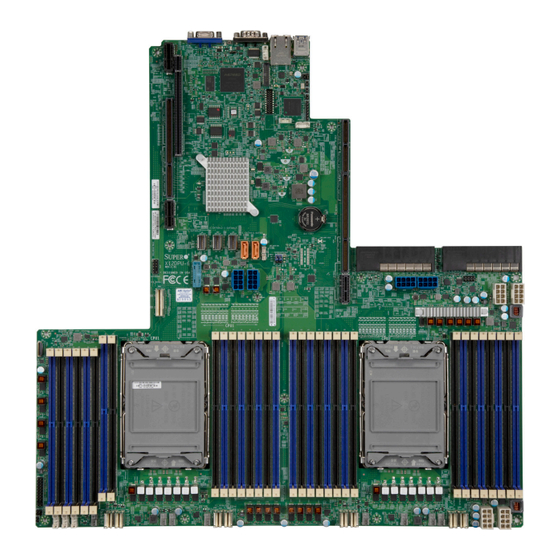
Chapter 1 Introduction Congratulations on purchasing your computer motherboard from an industry leader. Supermicro motherboards are designed to provide you with the highest standards in quality and performance. 1.1 Checklist This motherboard was designed to be used with an SMCI-proprietary chassis as an integrated server platform. - Page 9 Chapter 1: Introduction Figure 1-1. X12DPU-6 Motherboard Image Note: All graphics shown in this manual were based upon the latest PCB revision available at the time of publication of the manual. The motherboard you received may or may not look exactly the same as the graphics shown in this manual.
- Page 10 Super X12DPU-6 User's Manual Figure 1-2. X12DPU-6 Motherboard Layout (not drawn to scale) COM1 BMC_LAN USB0/1(3.0) JUIDB JVGA1 LED1 SXB2 JUID JLAN1 SXB1A SXB1B BIOS1 BMC FW1 SXB3_1 JRK1 JVGA2 VROC JNVI2C4 BMC FW2 BIOS2 SXB3_2 PWR_On LED BATTERY SXB1C...
- Page 11 JTPM1 JGPW3 JGPW4 USB3/4 (3.0) JPW4 T-SGPIO3 BIOS JPW3 P1-NVMe0/1 GPU PWR1 GPU PWR2 LICENSE JGPW1 GPU3PW3 P2-DIMMF1 GPU3PW4 SXB3_3 JPW4 JPW3 X12DPU-6 P2-DIMMF2 P1-DIMMG2 P2-DIMME1 REV:1.02 P1-DIMMG1 P2-DIMME2 P2-DIMMB1 P2-DIMMB2 P1-DIMMH2 P2-DIMMA1 P1-DIMMH1 P2-DIMMA2 P1-DIMME2 P2-DIMMD1 P1-DIMME1 P2-DIMMD2 P1-DIMMF2...
- Page 12 Super X12DPU-6 User's Manual Quick Reference Table Jumper Description Default Setting JBT1 Clear CMOS Open (Normal) JUID UID Enable/BMC Reset Jumper Pins 1-2 (UID Enabled) Description Status LAN LED Ethernet LAN LED Indicators (Blink: Active) Power_on LED System Power LED: (On: System Power on)
- Page 13 Chapter 1: Introduction Connector Description T-SGPIO3 Serial_Link General-Purpose I/O connection header (for S-SATA 4/5 SuperDOM support) USB0/1 (3.0) Rear I/O USB 3.0 ports USB3/4 (3.0) Front accessible USB header with two USB 3.0 connections Backplane VGA port VROC (JRK1) Intel VROC Key Header for NVMe RAID...
- Page 14 Super X12DPU-6 User's Manual Motherboard Features Motherboard Features • Supports two 3rd Gen Intel Xeon Scalable Processors (in Socket P+) with up to 40 cores and the thermal design power (TDP) of up to 270W Memory • Up to 12TB of 3DS LRDIMM/LRDIMM/3DS RDIMM/RDIMM/NV-DIMM DDR4 (288-pin) ECC memory with speeds of 3200/2933/2666 MHz in 32 memory slots with Intel®...
- Page 15 Chapter 1: Introduction Motherboard Features Peripheral Devices • Two USB 3.0 ports on the rear I/O panel (USB0/1) • One front accessible USB 3.0 header with two (2) USB connections (USB3/4) BIOS • AMI BIOS • ACPI 3.0 or later, SMBIOS 2.7 or later, PCI F/W 3.0/4.0 support, BIOS rescue hot-key, SPI dual/quad speed support, riser card auto detection support, RTC (Real Time Clock) wakeup, and SMBIOS 3.0 or later Power Management •...
- Page 16 Note 1: The CPU maximum thermal design power (TDP) is subject to chassis and heatsink cooling restrictions. For proper thermal management, please check the chas- sis and heatsink specifications. Note 2: For BMC configuration instructions, please refer to the Embedded BMC Con- figuration User's Guide available at http://www.supermicro.com/support/manuals/.
- Page 17 Chapter 1: Introduction X12DPU-6 DDR4 NCSI DDR4 AST2600 BMC LAN RTL8211F RJ45 32MB BMC COM1 UART SPI FLASH LPC/eSPI Ultra IO Port A 32MB BIOS SPI FLASH Port B Header PE[5] LPC/eSPI Port B SATA Gen3 [0..3] 8~15 I-SATA0~3 SATA Gen3 [4..7] I-SATA4~7 sSATA Gen3 [0..3]...
-
Page 18: Processor And Chipset Overview
1.2 Processor and Chipset Overview Built upon the functionality and capability of the 3rd Gen Intel Xeon Scalable Processors (Socket P+) and the Intel C621A chipset, the X12DPU-6 motherboard provides system performance, energy efficiency, and feature sets optimized for high-performance computing, artificial intelligence (AI), deep learning (DL), big data, and enterprise applications. -
Page 19: Special Features
Chapter 1: Introduction 1.3 Special Features Recovery from AC Power Loss The Basic I/O System (BIOS) provides a setting that determines how the system will respond when AC power is lost and then restored to the system. You can choose for the system to remain powered off (in which case you must press the power switch to turn it back on), or for it to automatically return to the power-on state. -
Page 20: Acpi Features
It is even more important for processors that have high CPU clock rates where noisy power transmission is present. The X12DPU-6 motherboard accommodates two power supply units. Although most power supplies generally meet the specifications required by the CPU, some are inadequate. In addition, four backplane 12V 8-pin power connectors, and three 8-pin GPU power connectors are also required to ensure adequate power supply to the system. -
Page 21: Intel® Optane™ Pmem 200 Series Memory Overview
Chapter 1: Introduction 1.8 Intel® Optane™ PMem 200 Series Memory Overview The 3rd Gen Intel Xeon Scalable Processors support Intel Optane PMem 200 Series or next generation Optane PMem memory technology depending on the processors used in the system. Optane PRem memory offers data persistence at higher capacities than the traditional DDR3/DDR4 memory modules. -
Page 22: Chapter 2 Installation
Super X12DPU-6 User's Manual Chapter 2 Installation 2.1 Static-Sensitive Devices Electrostatic Discharge (ESD) can damage electronic com ponents. To avoid damaging your motherboard, it is important to handle it very carefully. The following measures are generally sufficient to protect your equipment from ESD. -
Page 23: Processor And Heatsink Installation
Thermal grease is pre-applied on a new heatsink. No additional thermal grease is needed. • Refer to the Supermicro website for updates on processor and memory support. • All graphics in this manual are for illustrations only. Your components may look different. - Page 24 Super X12DPU-6 User's Manual 1. The 3rd Gen Intel Xeon Scalable Processor Processor Top View (3D) CPU Key Pin 1 Cutout = Cutout = Pin 1 = CPU Key Processor Top View...
- Page 25 Chapter 2: Installation 2. Processor Carriers Carrier Top View Carrier Bottom View...
- Page 26 Super X12DPU-6 User's Manual 3. Heatsink Note: Exercise extreme care when handling the heatsink. Pay attention to the edges of heatsink fins which can be sharp! To avoid damaging the heatsink, please do not apply excessive force on the fins when handling the heatsink.
-
Page 27: Overview Of The Cpu Socket
Chapter 2: Installation Overview of the CPU Socket The CPU socket is protected by a plastic protective cover. Plastic Protective Cover CPU Socket... -
Page 28: Overview Of The Processor Carrier Assembly
Super X12DPU-6 User's Manual Overview of the Processor Carrier Assembly The processor carrier assembly contains a 3rd Gen Intel Xeon Scalable processor and a processor carrier. Carefully follow the instructions given in the installation section to place a processor into the carrier to create a processor carrier. -
Page 29: Overview Of The Processor Heatsink Module
Chapter 2: Installation Overview of the Processor Heatsink Module The Processor Heatsink Module (PHM) contains a heatsink, a processor carrier, and a 3rd Gen Intel Xeon Scalable processor. 1. Heatsink (with Thermal Grease) 2. Processor Carrier 3. 3rd Gen Intel Xeon Scalable Processor Bottom View 4. -
Page 30: Creating The Processor Carrier Assembly
Super X12DPU-6 User's Manual Creating the Processor Carrier Assembly The processor carrier assembly contains a 3rd Gen Intel Xeon Scalable processor and a processor carrier. To create the processor carrier assembly, please follow the steps below: Note: Before installation, be sure to follow the instructions given on Page 1 & Page 2 of this chapter to properly prepare yourself for installation. - Page 31 Chapter 2: Installation 3. Locate the lever on the CPU socket and press the lever down as shown below. Lever 4. Using Pin 1 as a guide, carefully align the CPU keys (A & B) on the processor against the CPU keys on the carrier (a & b) as shown in the drawing below. 5.
-
Page 32: Creating The Processor Heatsink Module (Phm)
Super X12DPU-6 User's Manual Creating the Processor Heatsink Module (PHM) After creating the processor carrier assembly, please follow the instructions below to mount the processor carrier into the heatsink to form the processor heatsink module (PHM). Note: If this is a new heatsink, the thermal grease has been pre-applied on the un- derside. -
Page 33: Preparing The Cpu Socket For Installation
Chapter 2: Installation Preparing the CPU Socket for Installation This motherboard comes with a plastic protective cover installed on the CPU socket. Remove it from the socket to install the Processor Heatsink Module (PHM). Gently pull up one corner of the plastic protective cover to remove it. CPU Socket with Plastic Protective Cover 1. -
Page 34: Preparing To Install The Processor Heatsink Module (Phm) Into The Cpu Socket
Super X12DPU-6 User's Manual Preparing to Install the Processor Heatsink Module (PHM) into the CPU Socket After assembling the Processor Heatsink Module (PHM), you are ready to install it into the CPU socket. To ensure the proper installation, please follow the procedures below: 1. -
Page 35: Installing The Processor Heatsink Module (Phm)
Chapter 2: Installation Installing the Processor Heatsink Module (PHM) 1. Align peek nut "A", which is next to the triangle (Pin 1) on the heatsink, against threaded fastener "a" on the CPU socket. Then align peek nuts "B", "C", "D" on the heatsink against threaded fasteners "b", "c", "d"... -
Page 36: Removing The Processor Heatsink Module From The Cpu Socket
Super X12DPU-6 User's Manual Removing the Processor Heatsink Module from the CPU Socket Before removing the processor heatsink module (PHM) from the motherboard, unplug the AC power cord from all power supplies after shutting down the system. Then follow the steps below: 1. - Page 37 Chapter 2: Installation Removing the Processor Carrier Assembly from the Processor Heatsink Module (PHM) To remove the processor carrier assembly from the PHM, please follow the steps below: 1. Detach four plastic clips (marked a, b, c, d) on the processor carrier assembly from the four corners of heatsink (marked A, B, C, D) in the drawings below.
-
Page 38: Removing The Processor From The Processor Carrier Assembly
Super X12DPU-6 User's Manual Removing the Processor from the Processor Carrier Assembly Once you have removed the processor carrier assembly from the PHM, you are ready to remove the processor from the processor carrier by following the steps below. 1. Unlock the lever from its locking position and push the lever upwards to disengage the processor from the processor carrier as shown in the right drawing below. -
Page 39: Motherboard Installation
SATA4 SATA5 JGPW3 JGPW4 T-SGPIO3 BIOS GPU PWR2 GPU PWR1 LICENSE SXB3_3 JPW4 JPW3 X12DPU-6 REV:1.02 CPU2 CPU1 JPW2 JPW1 P1_NVMe6 P1_NVMe5 JNVI2C3 Location of Mounting Holes Note 1: To avoid damaging the motherboard and its components, please do not use a force greater than 8 lbf-in on each mounting screw during motherboard installation. - Page 40 Super X12DPU-6 User's Manual Installing the Motherboard 1. Install the I/O shield into the back of the chassis, if applicable. 2. Locate the mounting holes on the motherboard. See the previous page for the location. 3. Locate the matching mounting holes on the chassis. Align the mounting holes on the motherboard against the mounting holes on the chassis.
-
Page 41: Memory Support And Installation
Memory Support The X12DPU-6 supports up to 12TB of 3DS LRDIMM/LRDIMM/3DS RDIMM/RDIMM-NV- DIMM DDR4 (288-pin) ECC memory with speeds of 3200/2933/2666 MHz in 32 memory slots with Intel Optane PMem 200 Series memory support (See the notes below.) Note 1: Intel Optane PMem 200 Series memory is supported by the 3rd Gen Intel Xeon Scalable (83xx/63xx/53xx/4314 Series) Processors only. - Page 42 2 CPUs & 28 DIMMs CPU2: P2-DIMMA1/P2-DIMME1/P2-DIMMC1/P2-DIMMG1/P2-DIMMB1/P2-DIMMF1/P2-DIMMD1/P2-DIMMH1/ P2-DIMMA2/P2-DIMME2/P2-DIMMC2/P2-DIMMG2 CPU1: P1-DIMMA1/P1-DIMME1/P1-DIMMC1/P1-DIMMG1/P1-DIMMB1/P1-DIMMF1/P1-DIMMD1/P1-DIMMH1/ 2 CPUs & 32 DIMMs P1-DIMMA2/P1-DIMME2/P1-DIMMC2/P1-DIMMG2/P1-DIMMB2/P1-DIMMF2/P1-DIMMD2/P1-DIMMH2 (Note) CPU2: P2-DIMMA1/P2-DIMME1/P2-DIMMC1/P2-DIMMG1/P2-DIMMB1/P2-DIMMF1/P2-DIMMD1/P2-DIMMH1/ P2-DIMMA2/P2-DIMME2/P2-DIMMC2/P2-DIMMG2/P2-DIMMB2/P2-DIMMF2/P2-DIMMD2/P2-DIMMH2 Note: This memory configuration is recommended by Supermicro for optimal memory performance. Please use this configuration to maximize your memory performance.
- Page 43 Chapter 2: Installation PMem 200 Series Population table ® Note: The Intel Optane Persistent Memory (PMem) 200 Series are supported by the 3rd gen Intel Xeon Scalable (83xx/63xx/53xx/4314 Series) Processors. PMem 200 Series Population Table for X12DP 32-DIMM Motherboards (within 1 CPU socket) DDR4+ AD Inter- Mode...
- Page 44 Super X12DPU-6 User's Manual Validation Matrix (DDR4 DIMMS with PMem 200 Series) DIMM Capacity (GB) Ranks Per DIMM DIMM Type & Data Width DRAM Density (Stack) 16Gb 1Rx8 1Rx4 16GB 32GB RDIMM (up to 3200) 1Rx8 16GB 32GB 1Rx4 32GB...
- Page 45 SATA4 SATA5 JGPW3 JGPW4 T-SGPIO3 BIOS GPU PWR2 GPU PWR1 LICENSE SXB3_3 JPW4 JPW3 X12DPU-6 REV:1.02 2. Push the release tabs outwards on both ends of the DIMM slot to unlock it. CPU2 CPU1 JPW2 JPW1 P1_NVMe6 P1_NVMe5 JNVI2C3 Release Tabs 3.
-
Page 46: Rear I/O Ports
Super X12DPU-6 User's Manual 2.5 Rear I/O Ports See Figure 2-1 below for the locations and descriptions of the various I/O ports on the rear of the motherboard. COM1 BMC_LAN USB0/1(3.0) JUIDB JVGA1 LED1 SXB2 JUID JLAN1 SXB1A SXB1B BIOS1... - Page 47 BMC FW2 BIOS2 SXB3_2 PWR_On LED BATTERY SXB1C PW Supply2 PSU2 PW Supply1 PSU1 JBT1 JSD2 JSD1 SATA4 SATA5 JGPW3 JGPW4 T-SGPIO3 BIOS GPU PWR2 GPU PWR1 LICENSE SXB3_3 JPW4 JPW3 X12DPU-6 REV:1.02 CPU2 CPU1 JPW2 JPW1 P1_NVMe6 P1_NVMe5 JNVI2C3...
- Page 48 Super X12DPU-6 User's Manual BMC LAN An BMC dedicated LAN (BMC LAN) is located next to COM Port 1 on the I/O back panel. The dedicated BMC LAN provides LAN support via the BMC (Baseboard Management Controller). This LAN port accepts an RJ45 cable.
- Page 49 BMC FW2 BIOS2 SXB3_2 PWR_On LED BATTERY SXB1C PW Supply2 PSU2 PW Supply1 PSU1 JBT1 JSD2 JSD1 SATA4 SATA5 JGPW3 JGPW4 T-SGPIO3 BIOS GPU PWR2 GPU PWR1 LICENSE SXB3_3 JPW4 JPW3 X12DPU-6 REV:1.02 CPU2 CPU1 JPW2 JPW1 P1_NVMe6 P1_NVMe5 JNVI2C3...
- Page 50 BMC on the motherboard. For more details on the UID LEDs and BMC LEDs, refer to the tables below. Also, refer to the BMC User's Guide posted on our website at http://www.supermicro.com for more information on BMC. UID/BMC Reset Switch (JUIDB)-Features & Settings...
-
Page 51: Front Control Panel
JF1 contains header pins for various buttons and indicators that are normally located on a control panel at the front of the chassis. These connectors are designed specifically for use with Supermicro chassis. See the figure below for the descriptions of the front control panel buttons and LED indicators. - Page 52 Super X12DPU-6 User's Manual Front Control Panel LEDs Front Control Panel (JF1) LED Indicators Event Power (LED1) HDD (LED2) LAN (LED3/4) UID (LED5) Information (LED5) Power Fail (LED6) Power On Solid On HDD Activity Blinking NIC Activity Blinking Overheat Solid On...
- Page 53 Chapter 2: Installation Power On & BMC/BIOS Status LED Button The Power On and BMC/BIOS Status LED button is located on pins 1 and 2 of JF1. Momentarily contacting both pins will power on/off the system or display BMC/BIOS status. Refer to the tables below for more information.
- Page 54 Super X12DPU-6 User's Manual Power Fail LED The Power Fail LED connection is located on pins 5 and 6 of JF1. Refer to the table below for pin definitions. Power Fail LED Pin Definitions (JF1) Pin# Definition 3.3V PWR Fail for LED6 (Solid red on: PWR failure)
- Page 55 Chapter 2: Installation NIC1/NIC2 (LAN1/LAN2) The NIC (Network Interface Controller) LED connection for LAN port 1 is located on pins 11 and 12 of JF1, and LAN port 2 is on pins 9 and 10. Refer to the tables below for pin definitions. LAN1/LAN2 LED LAN1/LAN2 LED Pin Definitions (JF1)
- Page 56 Super X12DPU-6 User's Manual Front Panel Power LED The Power LED connection is located on pins 15 and 16 of JF1. Refer to the table below for pin definitions. Power LED Pin Definitions (JF1) Pins Definition 3.3V PWR LED NMI Button The non-maskable interrupt (NMI) button header is located on pins 19 and 20 of JF1.
-
Page 57: Connectors
8. JGPW2: 8-Pin PWR (GPU PWR2) SATA4 SATA5 JGPW3 JGPW4 T-SGPIO3 BIOS GPU PWR2 GPU PWR1 LICENSE 9. JGPW3: 8-Pin PWR (GPU PWR3) SXB3_3 JPW4 JPW3 X12DPU-6 REV:1.02 10. JGPW4: 8-Pin PWR (GPU PWR4) CPU2 CPU1 JPW2 JPW1 P1_NVMe6 P1_NVMe5 JNVI2C3... - Page 58 Super X12DPU-6 User's Manual Headers Fan Headers There are eight 4-pin fan headers (FAN1 ~ FAN8) on the motherboard. All these 4-pin fan headers are backwards compatible with the traditional 3-pin fans. However, fan speed control is available for 4-pin fans only by Thermal Management via BMC. Refer to the table below for pin definitions.
- Page 59 BMC FW2 BIOS2 SXB3_2 PWR_On LED BATTERY SXB1C PW Supply2 PSU2 PW Supply1 PSU1 JBT1 JSD2 JSD1 SATA4 SATA5 JGPW3 JGPW4 T-SGPIO3 BIOS GPU PWR2 GPU PWR1 LICENSE SXB3_3 JPW4 JPW3 X12DPU-6 REV:1.02 CPU2 CPU1 JPW2 JPW1 P1_NVMe6 P1_NVMe5 JNVI2C3...
- Page 60 The JTPM1 header is used to connect a Trusted Platform Module (TPM), which is available from Supermicro (optional). A TPM connector is a security device that supports encryption and authentication in hard drives. It allows the motherboard to deny access if the TPM associated with the hard drive is not installed in the system.
- Page 61 BMC FW2 BIOS2 SXB3_2 PWR_On LED BATTERY SXB1C PW Supply2 PSU2 PW Supply1 PSU1 JBT1 JSD2 JSD1 SATA4 SATA5 JGPW3 JGPW4 T-SGPIO3 BIOS GPU PWR2 GPU PWR1 LICENSE SXB3_3 JPW4 JPW3 X12DPU-6 REV:1.02 CPU2 CPU1 JPW2 JPW1 P1_NVMe6 P1_NVMe5 JNVI2C3...
- Page 62 Super X12DPU-6 User's Manual NCSI Connector Use the NCSI (Network Controller SideBand Interface) connector, located at (JNSCI), to connect a Network Interface Card (NIC) to the motherboard for network interface. Refer to the layout below for the location of JNSCI.
- Page 63 BMC FW2 BIOS2 SXB3_2 PWR_On LED BATTERY SXB1C PW Supply2 PSU2 PW Supply1 PSU1 JBT1 JSD2 JSD1 SATA4 SATA5 JGPW4 JGPW3 T-SGPIO3 BIOS GPU PWR2 GPU PWR1 LICENSE SXB3_3 JPW4 JPW3 X12DPU-6 REV:1.02 CPU2 CPU1 JPW2 JPW1 P1_NVMe6 P1_NVMe5 JNVI2C3...
- Page 64 Super X12DPU-6 User's Manual NVMe Connectors Five NVMe connectors (P1_NVMe1/3/4/5/6), supported by Processor #1, provide five NVMe connections. In addition, four NVMe connectors (P2_NVMe7/8/9/10), supported by Processor #2, also provide four NVMe connections on the motherboard. Use these NVMe connections to support high-speed PCIe storage devices.
- Page 65 Chapter 2: Installation I-SATA 3.0 and S-SATA 3.0 Ports The X12DPU-6 has eight I-SATA 3.0 ports (I-SATA 0-3, I-SATA 4-7) and six S-SATA (S-SATA 0-3, S-SATA 4, S-SATA 5) on the motherboard. These SATA ports are supported by the C621A chipset.
-
Page 66: Jumper Settings
Super X12DPU-6 User's Manual 2.8 Jumper Settings Connector Pins How Jumpers Work Jumper To modify the operation of the motherboard, jumpers can be used to choose between optional settings. Jumpers create shorts Setting between two pins to change the function of the connector. Pin 1 is identified with a square solder pad on the printed circuit board. - Page 67 BMC FW2 BIOS2 SXB3_2 PWR_On LED BATTERY SXB1C PW Supply2 PSU2 PW Supply1 PSU1 JBT1 JSD2 JSD1 SATA4 SATA5 JGPW4 JGPW3 T-SGPIO3 BIOS GPU PWR2 GPU PWR1 LICENSE SXB3_3 JPW4 JPW3 X12DPU-6 REV:1.02 CPU2 CPU1 JPW2 JPW1 P1_NVMe6 P1_NVMe5 JNVI2C3...
-
Page 68: Led Indicators
Super X12DPU-6 User's Manual 2.9 LED Indicators BMC LAN LEDs BMC LAN is located next to COM Port 1 on the rear I/O panel. The amber LED on the right indicates activity, while the green LED on the left indicates the speed of the connection. Refer to the table below for more information. - Page 69 BMC FW2 BIOS2 SXB3_2 PWR_On LED BATTERY SXB1C PW Supply2 PSU2 PW Supply1 PSU1 JBT1 JSD2 JSD1 SATA4 SATA5 JGPW3 JGPW4 T-SGPIO3 BIOS GPU PWR2 GPU PWR1 LICENSE SXB3_3 JPW4 JPW3 X12DPU-6 REV:1.02 CPU2 CPU1 JPW2 JPW1 P1_NVMe6 P1_NVMe5 JNVI2C3...
- Page 70 Super X12DPU-6 User's Manual Onboard Power LED The Onboard Power LED is located at LE2 on the motherboard. When this LED is on, the system power is on. Be sure to turn off the system power and unplug the power cord before removing or installing components.
-
Page 71: Chapter 3 Troubleshooting
Chapter 3: Troubleshooting Chapter 3 Troubleshooting 3.1 Troubleshooting Procedures Use the following procedures to troubleshoot your system. If you have followed all of the procedures below and still need assistance, refer to the ‘Technical Support Procedures’ and/ or ‘Returning Merchandise for Service’ section(s) in this chapter. Always disconnect the AC power cord before adding, changing or installing any non hot-swap hardware components. - Page 72 Super X12DPU-6 User's Manual No Video 1. If the power is on, but you have no video, remove all add-on cards and cables. 2. Remove all memory modules and turn on the system (Also, check the specs of memory modules, reset the memory or try a different one).
- Page 73 Chapter 3: Troubleshooting When the System Becomes Unstable A. If the system becomes unstable during or after OS installation, check the following: 1. CPU/BIOS support: Make sure that your CPU is supported and that you have the latest BIOS installed in your system. 2.
-
Page 74: Technical Support Procedures
Before contacting Technical Support, please take the following steps. Also, please note that as a motherboard manufacturer, Supermicro also sells motherboards through its channels, so it is best to first check with your distributor or reseller for troubleshooting services. They should know of any possible problems with the specific system configuration that was sold to you. -
Page 75: Frequently Asked Questions
Firmware Update and Recovery for the X12 Series Motherboards User Guide posted on the Product page in our website at www.supermicro.com. Note: The SPI BIOS chip used on this motherboard cannot be removed. Send your motherboard back to our RMA Department at Supermicro for repair. -
Page 76: Battery Removal And Installation
Super X12DPU-6 User's Manual 3.4 Battery Removal and Installation Battery Removal To remove the onboard battery, follow the steps below: 1. Power off your system and unplug your power cable. 2. Locate the onboard battery as shown below. 3. Using a tool such as a pen or a small screwdriver, push the battery lock outwards to unlock it. -
Page 77: Returning Merchandise For Service
For faster service, you can also request a RMA authorization online (http://www.supermicro. com/RmaForm/). This warranty only covers normal consumer use and does not cover damages incurred in shipping or from failure due to the alternation, misuse, abuse or improper maintenance of products. -
Page 78: Chapter 4 Uefi Bios
UEFI BIOS 4.1 Introduction This chapter describes the AMIBIOS™ setup utility for the X12DPU-6 motherboard. The BIOS is stored on a chip and can be easily upgraded using the BMC WebUI or the SUM utility. Note: Due to periodic changes to the BIOS, some settings may have been added or deleted and might not yet be recorded in this manual. -
Page 79: Main Setup
Note: The time is in the 24-hour format. For example, 5:30 P.M. appears as 17:30:00. The date's default value is the BIOS build date after the RTC (Real Time Clock) reset. Supermicro X12DPU-6 BIOS Version This feature displays the version of the BIOS ROM used in the system. - Page 80 Super X12DPU-6 User's Manual Memory Information Total Memory This feature displays the total size of memory available in the system.
-
Page 81: Advanced Setup Configurations
Chapter 4: UEFI BIOS 4.3 Advanced Setup Configurations Use the arrow keys to select the Advanced submenu and press <Enter> to access the submenu items: Warning: Take Caution when changing the Advanced settings. An incorrect value may cause the system to malfunction. When this occurs, restore the setting to the manufacturer default setting. Boot Feature ... - Page 82 Super X12DPU-6 User's Manual Wait For 'F1' If Error Select Enabled to force the system to wait until the <F1> key is pressed if an error occurs. The options are Enabled and Disabled. INT19 Trap Response Interrupt 19 is the software interrupt that handles the boot disk function. When this feature is set to Immediate, the ROM BIOS of the host adaptors will "capture"...
- Page 83 Chapter 4: UEFI BIOS Restore on AC Power Loss Use this feature to set the power state after a power outage. Select Power Off for the system power to remain off after a power loss. Select Power On for the system power to be turned on after a power loss.
- Page 84 Super X12DPU-6 User's Manual CPU Configuration Warning: Setting the wrong values in the following sections may cause the system to malfunc- tion. Processor Configuration The following CPU information will be displayed: Processor BSP Revision Processor Socket Processor ID...
- Page 85 Chapter 4: UEFI BIOS Core Disable Bitmap (Hex) Enter 0 to enable all CPU cores. Enter FFFFFFFFFFF to disable all CPU cores. Please note that at least one core per CPU must be enabled. Disabling all cores is not allowed. The default option is 0.
- Page 86 Super X12DPU-6 User's Manual Enable SMX (Not Available when "Enable Intel® TXT" is set to Enable) Select Enable to support Safer Mode Extensions (SMX) which provides a programming interface for system software to establish a controlled environment to support the trusted platform configured by the end user and to verify a virtual machine monitor before it is allowed to run.
- Page 87 Chapter 4: UEFI BIOS SW (Software) Guard Extensions (SGX) (Available when TME-MT is set to Enabled and the SGX feature is supported by the CPU used in the system) Select Enabled to support Software Guard Extensions (SGX) for memory data security enhancement.
- Page 88 Super X12DPU-6 User's Manual Advanced Power Management Configuration Power Technology Select Energy Efficient to support power-saving mode. Select Custom to customize system power settings. Select Disabled to disable power-saving settings. The options are Disable, Energy Efficient, and Custom. Power Performance Tuning (Available when "Power Technology" is set to Custom) Select BIOS to allow the system BIOS to configure the Power-Performance Tuning Bias setting.
- Page 89 Chapter 4: UEFI BIOS of applications so that the power-to-performance balance can be optimized for energy efficiency. The options are HW_ALL and SW_ALL Turbo Mode (Available when "SpeedStep" is set to Enable) Select enable to allow the CPU to operate at the manufacturer-defined turbo speed by increasing CPU clock frequency.
- Page 90 Super X12DPU-6 User's Manual Package C State Control (Available when "Power Technology" is set to Custom) Package C State Use this feature to optimize and reduce CPU package power consumption in idle mode. Please note that the changes you've made in this setting will affect all CPU cores or the circuits of the entire system.
- Page 91 Chapter 4: UEFI BIOS Chipset Configuration Warning: Setting the wrong values in the following items may cause the system to malfunction. North Bridge This feature allows the user to configure Intel North Bridge parameters. Uncore Configuration This section allows the user to configure the following Uncore settings: •...
- Page 92 Super X12DPU-6 User's Manual Degrade Precedence Use this feature to select the degrading precedence option for Ultra Path Interconnect (UPI) connections. Select Topology Precedent to degrade UPI features if the system options are in conflict. Select Feature Precedent to degrade UPI topology if system options are in conflict.
- Page 93 Chapter 4: UEFI BIOS Auto, Enable for Remote InvItoM Hybrid Push, InvItoM AllocFlow, Enable for Remote InvItoM Hybrid AllocNonAlloc, and Enable for Remote InvItoM and Remote WViLF. SNC (Sub NUMA) Select Enable to use "Sub NUMA Clustering" (SNC), which supports full SNC (2-cluster) interleave and 1-way IMC interleave.
- Page 94 Super X12DPU-6 User's Manual Memory Configuration This feature allows the user to configure the Integrated Memory Controller (iMC) settings. STEP DRAM Test Select Enable for Samsung Test BIOS and Enhanced Post Package Repair (PPR) support. The options are Enable and Disable. If this feature is set to Enable, the following feature...
- Page 95 Chapter 4: UEFI BIOS Memory Topology This item displays the information of onboard memory modules as detected by the BIOS: • P1-DIMMA1/P1-DIMMA2/P1-DIMMB1/P1-DIMMB2/P1-DIMMC1/P1-DIMMC2/P1-DIMMD1/P1-DIMMD2/P1-DIMME1/P1- DIMME2/P1-DIMMF1/P1-DIMMF2: 2934MT/s Hynix DRx4 32GB RDIMM • P2-DIMMA1/P2-DIMMA2/P2-DIMMB1/P2-DIMMB2/P2-DIMMC1/P2-DIMMC2/P2-DIMMD1/P2-DIMMD2/P2-DIMME1/P2- DIMME2/P2-DIMMF1/P2-DIMMF2: 2934MT/s Hynix DRx4 32GB RDIMM Memory RAS (Reliability_Availability_Serviceability) Configuration ...
- Page 96 Super X12DPU-6 User's Manual IIO Configuration CPU1 Configuration/CPU2 Configuration IOU0 (IIO PCIe Port 1) Use this feature to configure the PCIe Bifurcation setting for a PCIe port specified by the user. The options are x4x4x4x4, x4x4x8, x8x4x4, x8x8, x16, and Auto.
- Page 97 Chapter 4: UEFI BIOS Intel VT for Directed I/O (VT-d) Intel® VT for Directed I/O (VT-d) Select Enable to use the Intel Virtualization Technology support for Direct I/O VT-d by reporting the I/O device assignments to the VMM (Virtual Machine Monitor) through the DMAR ACPI tables.
- Page 98 Super X12DPU-6 User's Manual VMD Config (Configuration) for PCH Ports/VMD Config (Configuration) for IOU 0/ VMD Config (Configuration) for IOU 1//VMD Config (Configuration) for IOU 3/VMD Config (Configuration) for IOU 4 Ports (Available for onboard NVMe ports only) Enable/Disable VMD Select Enable to enable Intel Volume Management Device Technology support for the root port specified by the user.
- Page 99 Chapter 4: UEFI BIOS South Bridge The following South Bridge information will display: • USB Module Version • USB Devices Legacy USB Support Select Enabled to support onboard legacy USB devices. Select Auto to disable legacy support if there are no legacy USB devices present. Select Disable to have all USB devices available for EFI applications only.
- Page 100 Super X12DPU-6 User's Manual Server ME (Management Engine) Configuration This feature displays the following general ME configuration settings: • General ME Configuration • Oper. (Operation) Firmware Version • Backup Firmware Version • Recovery Firmware Version • ME Firmware Status #1/ME Firmware Status #2 •...
- Page 101 Chapter 4: UEFI BIOS PCH SATA Configuration PCH SATA Configuration SATA Controller This feature enables or disables the onboard SATA controller supported by the Intel PCH chip. The options are Enable and Disable. Configure SATA as (Available when "SATA Controller" is set to Enable) Select AHCI to configure a SATA drive specified by the user as an AHCI drive.
- Page 102 Super X12DPU-6 User's Manual SATA RAID Option ROM/UEFI Driver (Available when "Configure SATA as" is set to RAID) Select EFI to load the EFI driver for system boot. Select Legacy to load a legacy driver for system boot. The options are Disable, EFI, and Legacy.
- Page 103 Chapter 4: UEFI BIOS PCH sSATA Configuration PCH sSATA Configuration sSATA Controller This featured enables or disables the onboard sSATA controller supported by the Intel PCH. The options are Enable and Disable. Configure sSATA as (Available when "sSATA Controller" is set to Enable) Select AHCI to configure an sSATA drive specified by the user as an AHCI drive.
- Page 104 Super X12DPU-6 User's Manual sSATA RAID Option ROM/UEFI Driver (Available when "Configure sSATA as" is set to RAID) Select EFI to load the EFI driver for system boot. Select Legacy to load a legacy driver for system boot. The options are Disable, EFI, and Legacy.
- Page 105 Chapter 4: UEFI BIOS Network Configuration Network Stack Select Enabled to enable PXE (Preboot Execution Environment) or UEFI (Unified Extensible Firmware Interface) for network stack support. The options are Enabled and Disabled. *If "Network Stack" is set to Enabled, the following items will display: IPv4 PXE Support Select Enabled to enable IPv4 PXE boot support.
- Page 106 Super X12DPU-6 User's Manual Media Detect Time Use this feature to select the wait time (in seconds) for the BIOS ROM to detect the presence of a LAN media either via the Internet connection or via a LAN port. The default is 1.
- Page 107 Chapter 4: UEFI BIOS MAC: 0C42A1AE2ED2 - IPv4 Network Configuration Configured Select Enabled to show whether the network address has been successfully configured or not. The options are Enabled and Disabled. *If this feature is set to Enabled, the following items will display. Enable DHCP Select Enabled to support Dynamic Host Configuration Protocol (DHCP) which will allow the AMI BIOS to search for a DHCP server attached to the network and request the next...
- Page 108 Super X12DPU-6 User's Manual MAC: 0C42A1AE2ED2 - IPv6 Network Configuration Enter Configuration Menu The following features will display: • Interface Name • Interface Type • MAC Address • Host Addresses • Route Table • Gateway Addresses • DNS Addresses Interface ID This feature displays the Interface ID used in the network.
- Page 109 Chapter 4: UEFI BIOS MAC: 0C42A1AE2ED3 - IPv4 Network Configuration Configured Select Enabled to show whether the network address has been successfully configured or not. The options are Enabled and Disabled. *If this feature is set to Enabled, the following items will display. Enable DHCP Select Enabled to support Dynamic Host Configuration Protocol (DHCP) which will allow the AMI BIOS to search for a DHCP server attached to the network and request the next...
- Page 110 Super X12DPU-6 User's Manual MAC: 0C42A1AE2ED3 - IPv6 Network Configuration Enter Configuration Menu The following features will display: • Interface Name • Interface Type • MAC Address • Host Addresses • Route Table • Gateway Addresses • DNS Addresses Interface ID This feature displays the Interface ID used in the network.
- Page 111 Chapter 4: UEFI BIOS MAC: 0C42A1AE2EFE - IPv4 Network Configuration Configured Select Enabled to show whether the network address has been successfully configured or not. The options are Enabled and Disabled. *If this feature is set to Enabled, the following items will display. Enable DHCP Select Enabled to support Dynamic Host Configuration Protocol (DHCP) which will allow the AMI BIOS to search for a DHCP server attached to the network and request the next...
- Page 112 Super X12DPU-6 User's Manual MAC: 0C42A1AE2EFE - IPv6 Network Configuration Enter Configuration Menu The following features will display: • Interface Name • Interface Type • MAC Address • Host Addresses • Route Table • Gateway Addresses • DNS Addresses Interface ID This feature displays the Interface ID used in the network.
- Page 113 Chapter 4: UEFI BIOS MAC: 0C42A1AE2EFF - IPv4 Network Configuration Configured Select Enabled to show whether the network address has been successfully configured or not. The options are Enabled and Disabled. *If this feature is set to Enabled, the following items will display. Enable DHCP Select Enabled to support Dynamic Host Configuration Protocol (DHCP) which will allow the AMI BIOS to search for a DHCP server attached to the network and request the next...
- Page 114 Super X12DPU-6 User's Manual MAC: 0C42A1AE2EFF - IPv6 Network Configuration Enter Configuration Menu The following features will display: • Interface Name • Interface Type • MAC Address • Host Addresses • Route Table • Gateway Addresses • DNS Addresses Interface ID This feature displays the Interface ID used in the network.
- Page 115 Chapter 4: UEFI BIOS MAC: 0C42A1AE2EFA - IPv4 Network Configuration Configured Select Enabled to show whether the network address has been successfully configured or not. The options are Enabled and Disabled. *If this feature is set to Enabled, the following items will display. Enable DHCP Select Enabled to support Dynamic Host Configuration Protocol (DHCP) which will allow the AMI BIOS to search for a DHCP server attached to the network and request the next...
- Page 116 Super X12DPU-6 User's Manual MAC: 0C42A1AE2EFA - IPv6 Network Configuration Enter Configuration Menu The following features will display: • Interface Name • Interface Type • MAC Address • Host Addresses • Route Table • Gateway Addresses • DNS Addresses Interface ID This feature displays the Interface ID used in the network.
- Page 117 Chapter 4: UEFI BIOS MAC: 0C42A1AE2EFB - IPv4 Network Configuration Configured Select Enabled to show whether the network address has been successfully configured or not. The options are Enabled and Disabled. *If this feature is set to Enabled, the following items will display. Enable DHCP Select Enabled to support Dynamic Host Configuration Protocol (DHCP) which will allow the AMI BIOS to search for a DHCP server attached to the network and request the next...
- Page 118 Super X12DPU-6 User's Manual MAC: 0C42A1AE2EFB - IPv6 Network Configuration Enter Configuration Menu The following features will display: • Interface Name • Interface Type • MAC Address • Host Addresses • Route Table • Gateway Addresses • DNS Addresses Interface ID This feature displays the Interface ID used in the network.
- Page 119 Chapter 4: UEFI BIOS MAC: 0C42A1AE2EDE - IPv4 Network Configuration Configured Select Enabled to show whether the network address has been successfully configured or not. The options are Enabled and Disabled. *If this feature is set to Enabled, the following items will display. Enable DHCP Select Enabled to support Dynamic Host Configuration Protocol (DHCP) which will allow the AMI BIOS to search for a DHCP server attached to the network and request the next...
- Page 120 Super X12DPU-6 User's Manual MAC: 0C42A1AE2EDE - IPv6 Network Configuration Enter Configuration Menu The following features will display: • Interface Name • Interface Type • MAC Address • Host Addresses • Route Table • Gateway Addresses • DNS Addresses Interface ID This feature displays the Interface ID used in the network.
- Page 121 Chapter 4: UEFI BIOS MAC: 0C42A1AE2EDF - IPv4 Network Configuration Configured Select Enabled to show whether the network address has been successfully configured or not. The options are Enabled and Disabled. *If this feature is set to Enabled, the following items will display. Enable DHCP Select Enabled to support Dynamic Host Configuration Protocol (DHCP) which will allow the AMI BIOS to search for a DHCP server attached to the network and request the next...
- Page 122 Super X12DPU-6 User's Manual MAC: 0C42A1AE2EDF - IPv6 Network Configuration Enter Configuration Menu The following features will display: • Interface Name • Interface Type • MAC Address • Host Addresses • Route Table • Gateway Addresses • DNS Addresses Interface ID This feature displays the Interface ID used in the network.
- Page 123 Chapter 4: UEFI BIOS KMIP Server Configuration This feature displays the configuration settings for the KMIP (Key Management Interoperability Protocol) server, which will allow the clients to ask a server to encrypt or decrypt data without a direct access key. KMIP Server IP Address This feature displays the IP address for the KMIP server.
- Page 124 Super X12DPU-6 User's Manual Client Password Use this feature to enter a password for the KMIP server. KMS TLS Certificate | Size This feature displays the Transport Layer Security (TLS) Certificate and its size. CA Certificate Client Cerificate ...
- Page 125 Chapter 4: UEFI BIOS PCIe/PCI/PnP Configuration The following PCI information will be displayed: • PCI Bus Driver Version • PCI Devices Common Settings Above 4G Decoding (Available if the system supports 64-bit PCI decoding) Select Enabled to decode a PCI device that supports 64-bit in the space above 4G Address. The options are Enabled and Disabled.
- Page 126 Super X12DPU-6 User's Manual MMIOHBase Use this feature to select the base memory size according to memory-address mapping for the IO hub. The options are 56T, 40T, 32T, 24T, 16T, 4T, 2T, 1T, 512 G. MMIO High Granularity Size Use this feature to select the high memory size according to memory-address mapping for the IO hub.
- Page 127 Chapter 4: UEFI BIOS Super IO Configuration Super IO Chip AST2600 Serial Port 1 Configuration Serial Port 1 Select Enabled to enable Serial Port 1. The options are Enabled and Disabled. Device Settings (Available when "Serial Port 1" is set to Enabled) This feature displays the base I/O port address and the Interrupt Request address of Serial Port 1.
- Page 128 Super X12DPU-6 User's Manual Serial Port 2 Configuration Serial Port 2 Select Enabled to enable Serial Port 2. The options are Enabled and Disabled. Device Settings (Available when "Serial Port 2" is set to Enabled) This feature displays the base I/O port address and the Interrupt Request address of Serial Port 2.
- Page 129 Chapter 4: UEFI BIOS Serial Port Console Redirection COM 1 Console Redirection Select Enabled to enable COM Port 1 for Console Redirection, which will allow a client machine to be connected to a host machine at a remote site for networking. The options are Enabled and Disabled.
- Page 130 Super X12DPU-6 User's Manual Parity A parity bit can be sent along with regular data bits to detect data transmission errors. Select Even if the parity bit is set to 0, and the number of 1's in data bits is even. Select Odd if the parity bit is set to 0, and the number of 1's in data bits is odd.
- Page 131 Chapter 4: UEFI BIOS SOL (Serial-Over-LAN) Console Redirection (for SOL) Select Enabled to use the SOL port for Console Redirection. The options are Enabled and Disabled. *If the feature above is set to Enabled, the following items will become available for configuration: Console Redirection Settings (for SOL) ...
- Page 132 Super X12DPU-6 User's Manual Flow Control Use this feature to set the flow control for Console Redirection to prevent data loss caused by buffer overflow. Send a "Stop" signal to stop sending data when the receiving buffer is full. Send a "Start" signal to start data-sending when the receiving buffer is empty. The options are None and Hardware RTS/CTS.
- Page 133 Chapter 4: UEFI BIOS Legacy Console Redirection Settings Legacy Console Redirection Port Use this feature to select the COM port to display redirection of Legacy OS and Legacy OPROM messages. The options are COM1 and SOL. Legacy OS Redirection Resolution Use this feature to select the number of rows and columns used in Console Redirection for Legacy OS support.
- Page 134 Super X12DPU-6 User's Manual Bits Per Second This feature sets the transmission speed for a serial port used in Console Redirection. Make sure that the same speed is used in both host computer and the client computer. A lower transmission speed may be required for long and busy lines. The options are 9600, 19200, 57600, and 115200 (bits per second).
- Page 135 Chapter 4: UEFI BIOS ACPI Settings Use this feature to configure Advanced Configuration and Power Interface (ACPI) power management settings for your system. NUMA Select Enabled to enable Non-Uniform Memory Access support to enhance system performance. The options are Enabled and Disabled. UMA (Uniform Memory Access)-Based Clustering Select Enabled to enable UMA-based clustering to enhance system performance.
- Page 136 Super X12DPU-6 User's Manual Trusted Computing (Available when a TPM device is installed and detected by the BIOS) When a TPM (Trusted-Platform Module) device is detected in your machine, the following information will display: • TPM 2.0 Device Found: •...
- Page 137 Chapter 4: UEFI BIOS Pending Operation Use this feature to schedule a TPM-related operation to be performed by a security (TPM) device at the next system boot to enhance system data integrity. Your system will reboot to carry out a pending TPM operation. The options are None and TPM Clear. Note: Your system will reboot to carry out a pending TPM operation.
- Page 138 Super X12DPU-6 User's Manual TXT Support Select Enabled to enable Intel Trusted Execution Technology (TXT) support to enhance system integrity and data security. The options are Disabled and Enabled. Note 1: If the option for this feature (TXT Support) is set to Enabled, be sure to dis-...
- Page 139 Chapter 4: UEFI BIOS HTTP Boot Configuration When this submenu is selected, the following items will display: HTTP Boot Configuration HTTP Boot Policy Use this feature to set the HTTP Boot policy. The options are Apply to all LANs, Apply to Each LAN, and Boot Priority #1 instantly.
- Page 140 Super X12DPU-6 User's Manual iSCSI Configuration Attempt Priority Attempt Priority Use this feature to change the priority of iSCSI attempts using the + or - keys. The options are Host Attempt and Redfish Attempt. Commit Changes and Exit Select this feature to save the changes you've made and exit from the program.
- Page 141 Chapter 4: UEFI BIOS Intel® Ethernet Controller X710 for 10GBASE-T - 3C:EC:EF:1F:34:C2/Intel® Ethernet Controller X710 for 10GBASE-T - 3C:EC:EF:1F:34:C3 Firmware Image Properties The following information will be displayed: • Option ROM Version • Unique NVM/EEPROM ID • NVM Version NIC Configuration ...
- Page 142 Super X12DPU-6 User's Manual Blink LEDs This feature displays the number of blinking for the LAN LED indicators for a duration up to 15 seconds. The following information will be displayed as well: • UEFI Driver • Adapter PBA •...
- Page 143 Chapter 4: UEFI BIOS TLS Authenticate Configuration When this submenu is selected, the following items will display: Server CA Configuration This feature allows the user to configure the client certificate that is to be used by the server. Enroll Certification ...
- Page 144 Super X12DPU-6 User's Manual Delete Certification If this feature is set to Enabled, the certificate enrolled in the system will be deleted. The options are Enabled and Disabled. Client Certification Configuration This feature allows the user to configure the client certificate to be used by the server.
- Page 145 Chapter 4: UEFI BIOS NVMe SDD Drives Status (KIOXIA NVMe SSD 1700-00-0~84-00-0) Note: This section displays the information of all NVMe drives installed in your system. Since each system is configured differently, the items displayed on the screen will differ also.
- Page 146 Super X12DPU-6 User's Manual SAS3816 (PCISlot=0x3) Configuration Note: This feature allows the user to configure the PCIe slots installed in the system. Since each system has different PCI slot configuration, the items displayed on the screen will differ also. The section is provided for reference only.
- Page 147 Chapter 4: UEFI BIOS • Firmware Version • UEFI BSD HII Version: This feature displays the version of UEFI Boot Services Driver which manages the controller. • Legacy BIOS Version: This feature displays the version of Legacy x86 BIOS flashed on the controller.
- Page 148 Super X12DPU-6 User's Manual Intel® Optane™ Persistent Memory Configuration When you select this submenu and press <Enter>, the following screen will display: Intel® Optane™ Persistent Memory Configuration When you select this submenu and press <Enter>, the following screen will display: •...
- Page 149 Chapter 4: UEFI BIOS • DIMM Handle: This feature displays the unique handle assigned to the PMem module. • DIMM Physical ID: This feature displays the physical ID of the PMem module. • Manageability State: This feature indicates the manageability state of the PMem module. •...
- Page 150 Super X12DPU-6 User's Manual • Manufacturer: This feature indicates the • manufacturer of the PMem module. Show More Details Select Enabled to view more detailed information on the PMem module. The options are Disabled and Enabled. If this option is set to Enabled, the following items will display: •...
- Page 151 Chapter 4: UEFI BIOS • Channel Position • Revision ID • Form Factor • Manufacturer ID • Controller Revision ID • IS New • Memory Capacity • APP Direct Capacity • Unconfigured Capacity • Inaccessible Capacity • Reserved Capacity • Avg (Average) Power Limit [mW] •...
- Page 152 Super X12DPU-6 User's Manual • Configuration Status • SKU Violation • Population Violation • ARS Status • Overwrite PMem Module Status • Last Shutdown Time • Average Power Reporting Time Constant [mS] • Viral Policy Enable • Viral State •...
- Page 153 Chapter 4: UEFI BIOS • Media Temperature Injection Enabled • Master Passphrase Enabled • Average Power • Average Power 12V • Average Power 1.2V • eADR Enable • Previous PWR (Power) Cycle eADR Enabled • Latch System Shutdown State • Previous Power Cycle Latch System Showdown State •...
- Page 154 Super X12DPU-6 User's Manual • Modes Supported • Boot Status • AIT DRAM Enabled • Error Injection Enabled • Max Controller Temperature [C] • Software Triggers Enabled • Software Triggers Enabled Details • Poison Error Injections Counter • Poison Error Clear Counter •...
- Page 155 Chapter 4: UEFI BIOS Monitor Health This submenu displays the following health information on a memory module being monitored. • Current Alarm Threshold Status: This feature indicates the status of the current alarm threshold. • Controller Temperature [C]: This feature indicates the media temperature of the PMem memory.
- Page 156 Super X12DPU-6 User's Manual Regions Current Configuration Region ID 1/Region ID 2 When this submenu is selected, the following items will display: • Region ID: This feature displays the Region ID of the PMem module. • DIMM ID: This feature displays the DIMM ID of the PMem module.
- Page 157 Chapter 4: UEFI BIOS Provision This submenu configures the memory allocation goal for the onboard PMem memory modules. Create Goal Configuration When this submenu is selected, the following items will display: Create Goal Configuration for • Use this feature to select the target to create goal configuration for the PMem modules. The options are Platform and Socket.
- Page 158 Super X12DPU-6 User's Manual Namespaces This subsection allows the user to select a namespace to view the following information on the selected namespace Namespace ID/Name/Heath Status 0x00000201 Select this feature and press <Enter>, the following items will display: •...
- Page 159 Chapter 4: UEFI BIOS Create Namespace Use this submenu to create a namespace. The following information will display: Name Region ID This feature displays the Region ID of the PMem module. The options are 0x0001 and 0x0001. Mode Use this feature to set the Namespace mode. The options are None and Sector. Capacity Input Select Remaining to use the maximum memory capacity currently available as system memory capacity.
- Page 160 Super X12DPU-6 User's Manual Total Capacity This feature allows the user to set the total PMem resource capacity allocated across all segments in the host server. PMem Module Capacities This section displays the following information: • Volatile: This feature specifies Volatile information of the PMem module.
- Page 161 Chapter 4: UEFI BIOS Diagnostics Perform Diagnostic Tests on DIMMs When you select this submenu and press <enter>, the following items will display: Choose Diagnostics Type: Use this feature to choose the type of diagnostics test to be performed on the PMem module installed in the system Quick Diagnostics Select Enabled for the quick diagnostics test to be performed on the PMem module installed...
- Page 162 Super X12DPU-6 User's Manual Preferences View and/or modify user preferences Default DIMM ID This feature allows the user to view and to modify the default DIMM ID as displayed on the screen. The options are Handle and UID. Capacity Units This feature allows the user to view and to set the default capacity unit of the selected PMem to be displayed on the screen.
- Page 163 Chapter 4: UEFI BIOS Driver Health Note: This section displays the health information of the drives installed in your system. Since each system configuration differs, the items displayed on the screen will be dif- ferent. as well. This image above is provided for reference only.
-
Page 164: Event Logs
Super X12DPU-6 User's Manual 4.4 Event Logs Use this feature to configure Event Log settings. Note: After you've made any changes on a setting below, please reboot the system for the changes you've made to take effect. Change SMBIOS Event Log Settings... - Page 165 Chapter 4: UEFI BIOS SMBIOS Event Log Standard Settings Log System Boot Event Select Enabled to log system boot events. The options are Enabled and Disabled. MECI (Multiple Event Count Increment) Enter the increment value for the multiple event counter. Enter a number between 1 to 255. The default setting is 1.
-
Page 166: Bmc
Super X12DPU-6 User's Manual 4.5 BMC Use this feature to configure Sever Management settings. When you select this submenu and press <Enter>, the following information will display: • BMC Firmware Revision: This feature indicates the BMC firmware used in your system. - Page 167 Chapter 4: UEFI BIOS BMC Network Configuration --BMC Network Configuration-- Update BMC LAN Configuration Select Yes for the BIOS to implement all IP/MAC address changes upon next system boot. The options are No and Yes. *************************************************************************** Configure IPv4 Support *************************************************************************** This section displays the following BMC LAN information and allows you to configure BMC settings.
- Page 168 Super X12DPU-6 User's Manual *************************************************************************** Configure IPv6 Support *************************************************************************** IPv6 Address Status This feature displays the status of IPv6 addresses. IPv6 Support Select Enable to support IPv6 Connection. The options are Enabled and Disabled. Configuration Address Source Use this feature to select the source of the IPv6 Connection. If Static is selected, you will need to know the IP address of IPv6 connection and enter it to the system manually in the field.
-
Page 169: Security
Select Enabled to freeze the Lock Security feature for the HDDs to protect key data in hard drives from being altered. The options are Enabled and Disabled. Note: For detailed instructions on how to configure Secure Boot settings, please refer to the Secure Boot Configuration User's Guide posted on the web page under the link: http://www.supermicro.com/support/manuals/. - Page 170 Super X12DPU-6 User's Manual SMCI Security Erase Configuration This section allows the user to configure the SMCI-proprietary Security Erase settings. When this section is selected, the following features will display: • HDD Name: This feature displays the name of the HDD/SATA drive that is connected to the SMCI Security Erase Configuration submenu.
- Page 171 Chapter 4: UEFI BIOS Secure Boot Mode Use this feature to select the desired secure boot mode for the system. The options are Standard and Custom. CMS Support If this feature is set to Enabled, legacy devices will be supported by the system. The options are Enabled and Disabled.
- Page 172 Super X12DPU-6 User's Manual Secure Boot Variable/Size/Keys/Key Source Platform Key (PK) Use this feature to enter and configure a set of values to be used as platform firmware keys for the system. These values also indicate the sizes, keys numbers, and the sources of the authorized signatures.
- Page 173 Chapter 4: UEFI BIOS OsRecovery (OS Recovery) Signatures This feature allows the user to set and save the authorized signatures used for OS recovery. Select Update to update your "OS Recovery Signatures". These values also indicate sizes, keys, and key sources of the OsRecovery signatures. Select Append to append your "OS Recovery Signatures".
-
Page 174: Boot
Super X12DPU-6 User's Manual 4.7 Boot Use this feature to configure Boot Settings: Boot Mode Select Use this feature to select the type of devices from which the system will boot. The options are LEGACY, UEFI (Unified Extensible Firmware Interface), and DUAL. - Page 175 Chapter 4: UEFI BIOS Add New Boot Option This feature allows the user to add a new boot option to the boot priority features for system boot. Add Boot Option This feature allows the user to specify the name for the new boot option. Path for Boot Option Use this feature to enter the path for the new boot option in the format fsx:\path\filename.efi.
- Page 176 Super X12DPU-6 User's Manual USB Key Drive BBS Priorities Boot Option #1 Hard Disk Drive BBS Priorities Boot Option #1 Network Drive BBS Priorities Boot Option #1 ~ Boot Option #3...
-
Page 177: Save & Exit
Chapter 4: UEFI BIOS 4.8 Save & Exit Select the Save & Exit menu from the BIOS setup screen to configure the settings below. Save Options Discard Changes and Exit Select this option to exit from the BIOS setup utility without making any permanent changes to the system configuration and reboot the computer. - Page 178 Super X12DPU-6 User's Manual Default Options Restore Optimized Defaults To set this feature, select Restore Optimized Default Values from the Exit menu and press <Enter> to load manufacturer default settings which are intended for maximum system performance but not for maximum stability.
-
Page 179: Appendix A Software Installation
USB/SATA DVD drive, or a USB flash drive, or the BMC KVM console. 2. Retrieve the proper RST/RSTe driver. Go to the Supermicro web page for your motherboard and click on "Download the Latest Drivers and Utilities", select the proper driver, and copy it to a USB flash drive. - Page 180 Super X12DPU-6 User's Manual To load the driver, browse the USB flash drive for the proper driver files. • For RAID, choose the SATA/sSATA RAID driver indicated then choose the storage drive on which you want to install it. •...
- Page 181 The Supermicro website contains drivers and utilities for your system at https://www. supermicro.com/wdl/driver. Some of these must be installed, such as the chipset driver. After accessing the website, go into the CDR_Images (in the parent directory of the above link) and locate the ISO file for your motherboard. Download this file to a USB flash drive or a DVD.
- Page 182 A.3 SuperDoctor ® The Supermicro SuperDoctor 5 is a program that functions in a command-line or web-based interface for Windows and Linux operating systems. The program monitors such system health information as CPU temperature, system voltages, system power consumption, fan speed, and provides alerts via email or Simple Network Management Protocol (SNMP).
- Page 183 When logging in to the BMC for the first time, please use the unique password provided by Supermicro to log in. You can change the unique password to a user name and password of your choice for subsequent logins.
-
Page 184: Appendix B Standardized Warning Statements
The following statements are industry standard warnings, provided to warn the user of situations where a potential bodily injury may occur. Should you have questions or experience difficulty, contact Supermicro's Technical Support department for assistance. Only certified technicians should attempt to install or configure components. - Page 185 Appendix B: Standardized Warning Statements Attention Danger d'explosion si la pile n'est pas remplacée correctement. Ne la remplacer que par une pile de type semblable ou équivalent, recommandée par le fabricant. Jeter les piles usagées conformément aux instructions du fabricant. ¡Advertencia! Existe peligro de explosión si la batería se reemplaza de manera incorrecta.
- Page 186 Super X12DPU-6 User's Manual Product Disposal Warning! Ultimate disposal of this product should be handled according to all national laws and regulations. 製品の廃棄 この製品を廃棄処分する場合、 国の関係する全ての法律 ・ 条例に従い処理する必要があります。 警告 本产品的废弃处理应根据所有国家的法律和规章进行。 警告 本產品的廢棄處理應根據所有國家的法律和規章進行。 Warnung Die Entsorgung dieses Produkts sollte gemäß allen Bestimmungen und Gesetzen des Landes erfolgen.
Need help?
Do you have a question about the X12DPU-6 and is the answer not in the manual?
Questions and answers