Table of Contents
Advertisement
Advertisement
Table of Contents

Subscribe to Our Youtube Channel
Related Manuals for Supermicro X12DPi-N6


Summary of Contents for Supermicro X12DPi-N6
- Page 1 X12DP X12DP -NT6 USER'S MANUAL Revision 2.0a...
- Page 2 State of California, USA. The State of California, County of Santa Clara shall be the exclusive venue for the resolution of any such disputes. Supermicro's total liability for all claims will not exceed the price paid for the hardware product.
- Page 3 It provides information for the installation and use of the X12DPi-N(T)6 motherboard. About This Motherboard The Supermicro X12DPi-N6/X12DPi-NT6 supports dual 3rd Gen Intel® Xeon® Scalable Processors (in Socket P+ LGA 4189) with up to 40 CPU cores and a thermal design power (TDP) of up to 270W.
- Page 4 Super X12DPi-N6/X12DPi-NT6 User's Manual Contacting Supermicro Headquarters Address: Super Micro Computer, Inc. 980 Rock Ave. San Jose, CA 95131 U.S.A. Tel: +1 (408) 503-8000 Fax: +1 (408) 503-8008 Email: Marketing@supermicro.com (General Information) Sales-USA@supermicro.com (Sales Inquiry: Non-Government) Government_Sales-USA@supermicro.com (Sales Inquiry: Government) Support@supermicro.com (Technical Support)
-
Page 5: Table Of Contents
Preface Table of Contents Chapter 1 Introduction 1.1 Checklist ..........................7 1.2 Processor and Chipset Support ..................17 1.3 Special Features ........................17 1.4 System Health Monitoring ....................17 1.5 ACPI Features ........................18 1.6 Power Supply ........................18 1.7 Serial Port ...........................19 1.8 Intel® Optane™ Persistent Memory (PMem) 200 Series Overview ........19 Chapter 2 Installation 2.1 Static-Sensitive Devices .....................20 2.2 Processor and Heatsink Installation ...................21... - Page 6 Super X12DPi-N6/X12DPi-NT6 User's Manual Chapter 3 Troubleshooting 3.1 Troubleshooting Procedures ....................72 3.2 Technical Support Procedures ...................75 3.3 Frequently Asked Questions ....................76 3.4 Battery Removal and Installation ..................77 3.5 Returning Merchandise for Service ..................78 Chapter 4 UEFI BIOS 4.1 Introduction .........................79 4.2 Main Setup .........................80...
-
Page 7: Chapter 1 Introduction
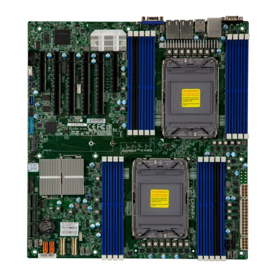
Introduction Congratulations on purchasing your computer motherboard from an industry leader. Supermicro motherboards are designed to provide you with the highest standards in quality and performance. In addition to the motherboard, several important parts that are included in the retail box are listed below. - Page 8 Super X12DPi-N6/X12DPi-NT6 User's Manual X12DPi-N(T)6 Motherboard Image Note: All graphics shown in this manual were based upon the latest PCB revision available at the time of publication of the manual. The motherboard you received may or may not look exactly the same as the graphics shown in this manual.
- Page 9 Chapter 1: Introduction X12DPi-N(T)6 Motherboard Layout (not drawn to scale) JVGA JLAN2 JLAN1 JUSBRJ45 COM1 LAN CTRL2 (*X12DPI-N6) FAN5 USB2/3 (3.0) LAN CTRL1 LAN2 LAN1 BMC_LAN/USB7/8(3.0) X12DPI-NT6 CPU2 Firmware BAR CODE BIOS CPLD X12DPi-N(T)6 MH16 MH15 REV:1.00 NVME BIOS LICENSE...
- Page 10 Super X12DPi-N6/X12DPi-NT6 User's Manual Quick Reference LANCTRL1 (X12DPi-NT6) LANCTRL2 (X12DPi-N6) UID/BMC Reset LEDM1 BMC_LAN Slot3 FAN5 USB2/3(3.0) Slot4 FAN6 JNCSI USB7/8(3.0) LAN2 LAN1 Slot2 Slot5 Slot6 COM1 JVGA Slot1 JLAN2 JLAN1 JUSBRJ45 COM1 LAN CTRL2 (*X12DPI-N6) FAN5 USB2/3 (3.0) P2-DIMMG1...
- Page 11 Standby power header JTPM1 Trusted Platform Module/Port 80 connector Ethernet LAN (RJ45) Port 1/ Port 2 (1G LAN support on X12DPi-N6 and 10G LAN support LAN1, LAN2 on X12DPi-NT6) PCIe 4.0 x4 M.2 slot (with support of M-Key 2280, and 22110) MH15, MH16 Mounting holes for M.2 keys (MH15: for M.2 Key 2280, MH16: for M.2 Key 22110)
- Page 12 Super X12DPi-N6/X12DPi-NT6 User's Manual SLOT6 PCIe 4.0 x8 slot supported by CPU2 S-SGPIO Serial Link General Purpose I/O connection header (for S-SATA4/5 SuperDOM support) USB0/1 (2.0) Front-accessible USB header with support for two USB 2.0 ports USB2/3, USB7/8 (3.0) Rear I/O USB 3.0 ports USB4/5 (3.0)
- Page 13 Two 10G Ethernet LAN ports supported by Intel X550 on LAN Controller 1 for X12DPi-NT6 • Two 1G Ethernet LAN ports supported by Intel i350 on LAN Controller 2 for X12DPi-N6 • One Dedicated BMC LAN located on the rear I/O panel (via AST2600 BMC) Baseboard Management Controller (BMC) •...
- Page 14 Super X12DPi-N6/X12DPi-NT6 User's Manual • One VGA port on the rear I/O panel (JVGA) • Video (VGA) Connections • One VGA header on the motherboard for front access (JFP2) Peripheral Devices • Four USB 3.0 ports on the rear I/O panel (USB2/3, USB7/8) •...
- Page 15 Note 1: The CPU maximum thermal design power (TDP) is subject to chassis and heatsink cooling restrictions. For proper thermal management, please check the chas- sis and heatsink specifications. Note 2: For BMC configuration instructions, please refer to the Embedded BMC Con- figuration User's Guide available at http://www.supermicro.com/support/manuals/.
- Page 16 Super X12DPi-N6/X12DPi-NT6 User's Manual X12DPi-N(T)6 CPU1-B1 CPU1-A1 CPU2-C1 CPU2-D1 CPU2-A1 CPU2-B1 CPU1-B2 CPU2-B2 CPU1-D1 CPU1-C1 CPU1 CPU2 (Socket ID:0) (Socket ID:1) DDR4 DDR4 CPU1-F1 CPU1-E1 CPU1-H1 CPU1-G1 CPU2-G1 CPU2-H1 CPU2-E1 CPU2-F1 PECI:30 PECI:31 DMI3 DMI3 PCIe X16 G4 PCIe X8 G4...
-
Page 17: Processor And Chipset Support
Chapter 1: Introduction 1.2 Processor and Chipset Support Built upon the functionality and capability of the 3rd Gen Intel Xeon Scalable Processors (Socket P+) and the Intel C621A chipset, the X12DPi-N(T)6 motherboard increases energy efficiency, and system performance for a multitude of applications such as high performance computing, artificial intelligence (AI), deep learning (DL), big data, and enterprise applications. -
Page 18: Acpi Features
System Health sensors monitor temperatures and voltage settings of onboard processors and the system in real time via the BMC interface. Whenever the temperature of the CPU or the system exceeds Supermicro’s pre-defined threshold, the system and CPU cooling fan speed will increase to prevent the CPU or system from overheating. -
Page 19: Serial Port
Chapter 1: Introduction It is strongly recommended that you use a high quality power supply that meets ATX power supply Specification 2.02 or above. It must also be SSI compliant. 1.7 Serial Port The X12DPi-N(T)6 motherboard supports two serial communication connections. COM Port 1 and COM Port 2 can be used for input/output. -
Page 20: Chapter 2 Installation
Super X12DPi-N6/X12DPi-NT6 User's Manual Chapter 2 Installation 2.1 Static-Sensitive Devices Electrostatic Discharge (ESD) can damage electronic com ponents. To avoid damaging your motherboard, it is important to handle it very carefully. The following measures are generally sufficient to protect your equipment from ESD. -
Page 21: Processor And Heatsink Installation
Thermal grease is pre-applied on a new heatsink. No additional thermal grease is needed. • Refer to the Supermicro website for updates on processor and memory support. • All graphics in this manual are for illustrations only. Your components may look different. - Page 22 Super X12DPi-N6/X12DPi-NT6 User's Manual 1. The 3rd Gen Intel Xeon Scalable Processor Processor Top View (3D) CPU Key Pin 1 = Cutout = CPU Key = Pin 1 Processor Top View...
- Page 23 Chapter 2: Installation 2. The Processor Carrier Carrier Bottom View...
- Page 24 Super X12DPi-N6/X12DPi-NT6 User's Manual 3. Heatsink Note: Exercise extreme care when handling the heatsink. Pay attention to the edges of heatsink fins which can be sharp! To avoid damaging the heatsink, please do not apply excessive force on the fins when handling the heatsink.
-
Page 25: Overview Of The Cpu Socket
Chapter 2: Installation Overview of the CPU Socket The CPU socket is protected by a plastic protective cover. Plastic Protective Cover CPU Socket... -
Page 26: Overview Of The Processor Carrier Assembly
Super X12DPi-N6/X12DPi-NT6 User's Manual Overview of the Processor Carrier Assembly The processor carrier assembly contains a 3rd Gen Intel Xeon Scalable processor and a processor carrier. Carefully follow the instructions given in the installation section to place a processor into the carrier to create a processor carrier. -
Page 27: Overview Of The Processor Heatsink Module
Chapter 2: Installation Overview of the Processor Heatsink Module The Processor Heatsink Module (PHM) contains a heatsink, a processor carrier, and a 3rd Gen Intel Xeon Scalable processor. 1. Heatsink (with Thermal Grease) 2. Processor Carrier 3. The 3rd Gen Intel Xeon Scalable Processor Bottom View 4. -
Page 28: Creating The Processor Carrier Assembly
Super X12DPi-N6/X12DPi-NT6 User's Manual Creating the Processor Carrier Assembly The processor carrier assembly contains a 3rd Gen Intel Xeon Scalable processor and a processor carrier. To create the processor carrier assembly, please follow the steps below: Note: Before installation, be sure to follow the instructions given on Page 1 & Page 2 of this chapter to properly prepare yourself for installation. - Page 29 Chapter 2: Installation 3. Locate the lever on the CPU socket and press the lever down as shown below. 4. Using Pin 1 as a guide, carefully align the CPU keys (A & B) on the processor against the CPU keys on the carrier (a & b) as shown in the drawing below. 5.
-
Page 30: Creating The Processor Heatsink Module (Phm)
Super X12DPi-N6/X12DPi-NT6 User's Manual Creating the Processor Heatsink Module (PHM) After creating the processor carrier assembly, please follow the instructions below to mount the processor carrier into the heatsink to form the processor heatsink module (PHM). Note: If this is a new heatsink, the thermal grease has been pre-applied on the un- derside. -
Page 31: Preparing The Cpu Socket For Installation
Chapter 2: Installation Preparing the CPU Socket for Installation This motherboard comes with a plastic protective cover installed on the CPU socket. Remove it from the socket by following the instructions given in the drawings below. Removing the Plastic Protective Cover from the Socket 1. -
Page 32: Preparing To Install The Processor Heatsink Module (Phm) Into The Cpu Socket
Super X12DPi-N6/X12DPi-NT6 User's Manual Preparing to Install the Processor Heatsink Module (PHM) into the CPU Socket After assembling the Processor Heatsink Module (PHM), you are ready to install it into the CPU socket. To ensure the proper installation, please follow the procedures below: 1. -
Page 33: Installing The Processor Heatsink Module (Phm)
Chapter 2: Installation Installing the Processor Heatsink Module (PHM) 1. Align PEEK nut "A", which is next to the triangle (Pin 1) on the heatsink, against threaded fastener "a" on the CPU socket. Then align PEEK nuts "B", "C", "D" on the heatsink against threaded fasteners "b", "c", "d"... -
Page 34: Removing The Processor Heatsink Module From The Cpu Socket
Super X12DPi-N6/X12DPi-NT6 User's Manual Removing the Processor Heatsink Module from the CPU Socket Before removing the processor heatsink module (PHM) from the motherboard, unplug the AC power cord from all power supplies after shutting down the system. Then follow the steps below: 1. - Page 35 Chapter 2: Installation Removing the Processor Carrier Assembly from the Processor Heatsink Module (PHM) To remove the processor carrier assembly from the PHM, please follow the steps below: 1. Detach four plastic clips (marked a, b, c, d) on the processor carrier assembly from the four corners of heatsink (marked A, B, C, D) in the drawings below.
-
Page 36: Removing The Processor From The Processor Carrier Assembly
Super X12DPi-N6/X12DPi-NT6 User's Manual Removing the Processor from the Processor Carrier Assembly Once you have removed the processor carrier assembly from the PHM, you are ready to remove the processor from the processor carrier by following the steps below. 1. Unlock the lever from its locking position and push the lever upwards to disengage the processor from the processor carrier as shown in the right drawing below. -
Page 37: Motherboard Installation
Tools Needed Phillips Screwdriver (1) Standoffs (9) Phillips Screws (9) (Only if Needed) JVGA JLAN2 JLAN1 JUSBRJ45 COM1 LAN CTRL2 (*X12DPI-N6) FAN5 USB2/3 (3.0) LAN CTRL1 LAN2 LAN1 BMC_LAN/USB7/8(3.0) X12DPI-NT6 CPU2 Firmware BAR CODE... - Page 38 Super X12DPi-N6/X12DPi-NT6 User's Manual Installing the Motherboard 1. Install the I/O shield into the back of the chassis, if applicable. 2. Locate the mounting holes on the motherboard. See the previous page for the location. 3. Locate the matching mounting holes on the chassis. Align the mounting holes on the motherboard against the mounting holes on the chassis.
-
Page 39: Memory Support And Installation
Chapter 2: Installation 2.4 Memory Support and Installation Note: Check the Supermicro website for recommended memory modules. Important: Exercise extreme care when installing or removing DIMM modules to pre- vent any possible damage. Memory Support The X12DPi-N(T)6 supports up to 4TB 3DS LRDIMM/LRDIMM/3DS RDIMM/RDIMM DDR4... - Page 40 (P2-DIMMB2: Reserved for PMem 200 Series only) ® Note 1: P1-DIMMB2 and P2-DIMMB2 are reserved for Intel Optane PMem 200 Series only. Note 2: This memory configuration is recommended by Supermicro for optimal memory performance. Please use this configuration to maximize your memory performance.
- Page 41 Chapter 2: Installation PMem 200 Series Population table for X12DP Motherboards (with 18 Slots) ® Note: The Intel Optane Persistent Memory (PMem) 200 Series are supported by the 3rd Gen Intel Xeon Scalable (83xx/63xx/53xx/4314 Series) Processors. PMem 200 Series Population Table for X12DP 18-DIMM Motherboards (within 1 CPU socket) DDR4+PMem Mode Interleave...
- Page 42 Super X12DPi-N6/X12DPi-NT6 User's Manual DIMM Installation JVGA JLAN2 JLAN1 JUSBRJ45 COM1 LAN CTRL2 (*X12DPI-N6) FAN5 USB2/3 (3.0) LAN CTRL1 LAN2 LAN1 BMC_LAN/USB7/8(3.0) X12DPI-NT6 1. Insert the desired number of DIMMs into the memory slots based on the recommended DIMM population tables CPU2 in the previous section.
-
Page 43: Rear I/O Ports
2.5 Rear I/O Ports See Figure 2-1 below for the locations and descriptions of the various I/O ports on the rear of the motherboard. JVGA JLAN2 JLAN1 JUSBRJ45 COM1 LAN CTRL2 (*X12DPI-N6) FAN5 USB2/3 (3.0) LAN CTRL1 LAN2 LAN1 BMC_LAN/USB7/8(3.0) X12DPI-NT6... - Page 44 Super X12DPi-N6/X12DPi-NT6 User's Manual VGA Connections There are two VGA connections in your system. The rear VGA port is located at JVGA on the rear I/O panel, and the front VGA header is located at JFP2 on the motherboard. These VGA connections provide analog interface support between the computer and the video displays.
- Page 45 SP_DCD2 SP_DSR2 SP_RXD2 SP_RTS2 SP_TXD2 SP_CTS2 SP_DTR2 SP_R12 Ground 1. COM1 JVGA JLAN2 JLAN1 JUSBRJ45 2. COM2 COM1 LAN CTRL2 (*X12DPI-N6) FAN5 USB2/3 (3.0) LAN CTRL1 LAN2 LAN1 BMC_LAN/USB7/8(3.0) X12DPI-NT6 CPU2 Firmware BAR CODE BIOS CPLD X12DPi-N(T)6 MH16 MH15 REV:1.00...
- Page 46 I/O panel. LAN1/LAN2 ports support 1 GbE LAN connection (via the Intel i350 LAN controller) on the X12DPi-N6, and support 10 GbE LAN connection (via the Intel X550 LAN controller) on the X12DPi-NT6. The dedicated BMC LAN, located above the USB2/3 ports on the rear I/O panel, provides LAN support for the BMC (Baseboard Management Controller).
- Page 47 Stda_SSTX+ USB3_TP USB_P Ground SSTX- JVGA SSTX+ JLAN2 JLAN1 JUSBRJ45 COM1 LAN CTRL2 (*X12DPI-N6) FAN5 USB2/3 (3.0) 1. Rear I/O Panel USB2/3 (3.0) LAN CTRL1 LAN2 LAN1 BMC_LAN/USB7/8(3.0) X12DPI-NT6 2. Rear I/O Panel USB7/8 (3.0) 3. USB0/1 (2.0) 4. USB4/5 (3.0) CPU2 5.
- Page 48 BMC on the motherboard. For more details on the UID LEDs and BMC LEDs, refer to the tables below. Also, refer to the BMC User's Guide posted on our website at http:// www.supermicro.com for more information on BMC. UID/BMC Reset Switch (JUIDB1) Features &...
-
Page 49: Front Control Panel
These connectors are designed specifically for use with Supermicro chassis. See the figure below for the descriptions of the front control panel buttons and LED indicators. - Page 50 Super X12DPi-N6/X12DPi-NT6 User's Manual Front Control Panel LEDs Front Control Panel (JF1) LED Indicators Event Power (LED1) HDD (LED2) LAN (LED3/4) UID (LED5) Information (LED5) Power Fail (LED6) Power On Solid On HDD Activity Blinking NIC Activity Blinking Overheat Solid On...
- Page 51 Chapter 2: Installation Power On Button The Power On button is located on pins 1 and 2 of JF1. Momentarily contacting both pins will power on/off the system. Refer to the tables below for more information. Power Button Pin Definitions (JF1) Pin# Definition Signal...
- Page 52 Super X12DPi-N6/X12DPi-NT6 User's Manual Power Fail LED The Power Fail LED connection is located on pins 5 and 6 of JF1. Refer to the table below for pin definitions. Power Fail LED Pin Definitions (JF1) Pin# Definition 3.3V PWR Fail for LED6 (Solid red on: PWR failure)
- Page 53 Chapter 2: Installation NIC1/NIC2 (LAN1/LAN2) The NIC (Network Interface Controller) LED connection for LAN port 1 is located on pins 11 and 12 of JF1, and LAN port 2 is on pins 9 and 10. Attach the NIC LED cables here to display network activity.
- Page 54 Super X12DPi-N6/X12DPi-NT6 User's Manual Power LED The Power LED connection is located on pins 15 and 16 of JF1. Refer to the table below for pin definitions. Power LED Pin Definitions (JF1) Pins Definition 3.3V PWR LED NMI Button The non-maskable interrupt (NMI) button header is located on pins 19 and 20 of JF1. Refer to the table below for pin definitions.
-
Page 55: Connectors
5VSB +12V +12V Ground +3.3V Required Connection JVGA JLAN2 JLAN1 JUSBRJ45 1. JPWR3: 24-Pin ATX PWR COM1 LAN CTRL2 (*X12DPI-N6) FAN5 USB2/3 (3.0) 2. JPWR2: 8-Pin PWR LAN CTRL1 LAN2 LAN1 BMC_LAN/USB7/8(3.0) X12DPI-NT6 3. JPWR4: 8-Pin PWR CPU2 Firmware BAR CODE... - Page 56 Super X12DPi-N6/X12DPi-NT6 User's Manual Headers Fan Headers There are eight 4-pin fan headers (FAN1-FAN6, FANA-FANB) on the motherboard. All these 4-pin fan headers are backwards compatible with the traditional 3-pin fans. However, fan speed control is available for 4-pin fans only by Thermal Management via the BMC interface.
- Page 57 Definition Pin# Definition Ground Data Load Ground Clock NC = No Connection JVGA JLAN2 JLAN1 JUSBRJ45 COM1 1. S-SGPIO LAN CTRL2 (*X12DPI-N6) FAN5 USB2/3 (3.0) LAN CTRL1 LAN1 LAN2 BMC_LAN/USB7/8(3.0) X12DPI-NT6 CPU2 Firmware BAR CODE BIOS CPLD X12DPi-N(T)6 MH15 MH16 REV:1.00...
- Page 58 The JTPM1 header is used to connect a Trusted Platform Module (TPM)/Port 80, which is available from Supermicro (optional). A TPM/Port 80 connector is a security device that supports encryption and authentication in hard drives. It allows the motherboard to deny access if the TPM associated with the hard drive is not installed in the system.
- Page 59 JVGA JLAN2 JLAN1 JUSBRJ45 COM1 LAN CTRL2 (*X12DPI-N6) FAN5 1. VROC RAID Key (JRK1) USB2/3 (3.0) LAN CTRL1 LAN2 LAN1 BMC_LAN/USB7/8(3.0)
- Page 60 Super X12DPi-N6/X12DPi-NT6 User's Manual Standby Power The Standby Power header is located at JSTBY1 on the motherboard. You must have a card with a Standby Power connector and a cable to use this feature. Refer to the table below for pin definitions.
- Page 61 Pin Definitions Pin# Definition Data Ground Clock No Connection 1. Power SMB Header JVGA JLAN2 JLAN1 JUSBRJ45 COM1 LAN CTRL2 2. BMC External Header (*X12DPI-N6) FAN5 USB2/3 (3.0) LAN CTRL1 LAN2 LAN1 BMC_LAN/USB7/8(3.0) X12DPI-NT6 CPU2 Firmware BAR CODE BIOS CPLD X12DPi-N(T)6...
- Page 62 C), used for PCIe SMBus clock and data connections, provides hot-plug support via a dedicated SMBus interface. This feature is only available for a Supermicro complete system with an SMCI-proprietary NVMe add-on card and a proper cable installed. See the table below for pin definitions.
- Page 63 M.2 slot and the mounting holes. 1. M.2 Slot JVGA JLAN2 JLAN1 JUSBRJ45 2. MH15 (for M.2 Key 2280) COM1 LAN CTRL2 (*X12DPI-N6) FAN5 USB2/3 (3.0) LAN CTRL1 LAN2 LAN1 3. MH16 (for M.2 Key 22110) BMC_LAN/USB7/8(3.0)
- Page 64 Super X12DPi-N6/X12DPi-NT6 User's Manual SlimSAS NVMe Connectors Two SlimSAS NVMe connectors provide four NVMe connections (P1_NVME0/1, P1_ NVME2/3). Use these NVMe connections to attach high-speed PCIe storage devices. Note: When installing an NVMe device on a motherboard, please be sure to connect the first NVMe port (P1_NVME0/1) first for your system to work properly.
- Page 65 The X12DPi-N(T)6 has eight I-SATA 3.0 ports (I-SATA0-3, I-SATA4-7) and six S-SATA (S-SATA0-3, S-SATA4, S-SATA5) on the motherboard. These SATA ports are supported by the C621A chipset. S-SATA4/S-SATA5 can be used with Supermicro SuperDOMs which are orange SATA DOM connectors with power pins built in, and do not require external power cables.
-
Page 66: Jumper Settings
Super X12DPi-N6/X12DPi-NT6 User's Manual 2.8 Jumper Settings Connector Pins How Jumpers Work Jumper To modify the operation of the motherboard, jumpers can be used to choose between optional settings. Jumpers Setting create shorts between two pins to change the function of the connector. - Page 67 LAN Enable/Disable Jumper Settings Jumper Setting Definition Pins 1-2 Enabled Pins 2-3 Disabled 1. JPL1 JVGA JLAN2 JLAN1 JUSBRJ45 COM1 LAN CTRL2 (*X12DPI-N6) FAN5 USB2/3 (3.0) LAN CTRL1 LAN2 LAN1 BMC_LAN/USB7/8(3.0) X12DPI-NT6 CPU2 Firmware BAR CODE BIOS CPLD X12DPi-N(T)6 MH16 MH15 REV:1.00...
- Page 68 Super X12DPi-N6/X12DPi-NT6 User's Manual ME Recovery JPME1 is used for ME Firmware Recovery mode, which will limit system resource for essential function use only without putting restrictions on power use. In the single operation mode, online upgrade will be available via Recovery mode. See the table below for pin definitions.
-
Page 69: Led Indicators
1Gbps IPMI LAN Activity (Right) Amber: Blinking Active (X8ST3-F) 1. LAN1/LAN2 LEDs JVGA JLAN2 JLAN1 JUSBRJ45 COM1 LAN CTRL2 2. BMC LAN LEDs (*X12DPI-N6) FAN5 USB2/3 (3.0) LAN CTRL1 LAN2 LAN1 BMC_LAN/USB7/8(3.0) X12DPI-NT6 CPU2 Firmware BAR CODE BIOS CPLD X12DPi-N(T)6... - Page 70 Super X12DPi-N6/X12DPi-NT6 User's Manual M.2 LED An M.2 LED is located at LE4 on the motherboard. When LE4 is blinking, M.2 functions normally. Refer to the table below for more information. M.2 LED State LED Color Definition Green: Blinking Device Working 1.
- Page 71 Note: For information on UID LED Indicators and BMC Heartbeat LED Indicator, please refer to the section on UID LED/BMC Reset Switch and LED Indicator on page 48. 1. Onboard Power LED JVGA JLAN2 JLAN1 JUSBRJ45 COM1 LAN CTRL2 (*X12DPI-N6) FAN5 USB2/3 (3.0) LAN CTRL1 LAN2 LAN1 BMC_LAN/USB7/8(3.0) X12DPI-NT6...
-
Page 72: Chapter 3 Troubleshooting
Super X12DPi-N6/X12DPi-NT6 User's Manual Chapter 3 Troubleshooting 3.1 Troubleshooting Procedures Use the following procedures to troubleshoot your system. If you have followed all of the procedures below and still need assistance, refer to the ‘Technical Support Procedures’ and/ or ‘Returning Merchandise for Service’ section(s) in this chapter. Always disconnect the AC power cord before adding, changing or installing any non hot-swap hardware components. - Page 73 Chapter 3: Troubleshooting No Video 1. If the power is on, but you do not have video, remove all add-on cards and cables. 2. Remove all memory modules and turn on the system (if the alarm is on, check the specs of memory modules, reset the memory, or try a different one).
- Page 74 Super X12DPi-N6/X12DPi-NT6 User's Manual When the System Becomes Unstable A. If the system becomes unstable during or after OS installation, check the following: 1. CPU/BIOS support: Make sure that your CPU is supported and that you have the latest BIOS installed in your system.
-
Page 75: Technical Support Procedures
Before contacting Technical Support, please take the following steps. Also, please note that as a motherboard manufacturer, Supermicro also sells motherboards through its channels, so it is best to first check with your distributor or reseller for troubleshooting services. They should know of any possible problems with the specific system configuration that was sold to you. -
Page 76: Frequently Asked Questions
BIOS revision to make sure that it is newer than your BIOS before downloading. Note 1: The SPI BIOS chip used on this motherboard cannot be removed. Send your motherboard back to our RMA Department at Supermicro for repair. Note 2: For BIOS Update and Recovery instructions, please refer to the Firmware Update and Recovery Instructions for Supermicro's X12 Motherboards User's Guide posted at http://www.supermicro.com/support/manuals/. -
Page 77: Battery Removal And Installation
Chapter 3: Troubleshooting 3.4 Battery Removal and Installation Battery Removal To remove the onboard battery, follow the steps below: 1. Power off your system and unplug your power cable. 2. Locate the onboard battery as shown below. 3. Using a tool such as a pen or a small screwdriver, push the battery lock outwards to unlock it. -
Page 78: Returning Merchandise For Service
Super X12DPi-N6/X12DPi-NT6 User's Manual 3.5 Returning Merchandise for Service A receipt or copy of your invoice marked with the date of purchase is required before any warranty service will be rendered. You can obtain service by calling your vendor for a Returned Merchandise Authorization (RMA) number. -
Page 79: Chapter 4 Uefi Bios
Chapter 4 UEFI BIOS 4.1 Introduction This chapter describes the AMIBIOS™ setup utility for the X12DPi-N6/X12DPi-NT6 motherboard. The BIOS is stored on a chip and can be easily upgraded using the BMC WebUI or the SUM utility. Note: Due to periodic changes to the BIOS, some settings may have been added or deleted and might not yet be recorded in this manual. -
Page 80: Main Setup
Super X12DPi-N6/X12DPi-NT6 User's Manual 4.2 Main Setup When you first enter the AMI BIOS setup utility, you will see the Main setup screen. You can always return to the Main setup screen by selecting the Main tab on the top of the screen. - Page 81 Chapter 4: UEFI BIOS Memory Information Total Memory This feature displays the total size of memory available in the system.
-
Page 82: Advanced Setup Configurations
Super X12DPi-N6/X12DPi-NT6 User's Manual 4.3 Advanced Setup Configurations Use the arrow keys to select the Advanced submenu and press <Enter> to access the submenu items: Warning: Take Caution when changing the Advanced settings. An incorrect value may cause the system to malfunction. When this occurs, restore the setting to the manufacturer default setting. - Page 83 Chapter 4: UEFI BIOS Wait For 'F1' If Error Select Enabled to force the system to wait until the <F1> key is pressed if an error occurs. The options are Enabled and Disabled. INT19 Trap Response Interrupt 19 is the software interrupt that handles the boot disk function. When this feature is set to Immediate, the BIOS ROM of the host adaptors will "capture"...
- Page 84 Super X12DPi-N6/X12DPi-NT6 User's Manual Restore on AC Power Loss Use this feature to set the power state after a power outage. Select Power Off for the system power to remain off after a power loss. Select Power On to turn on the system power after a power loss.
- Page 85 Chapter 4: UEFI BIOS CPU Configuration Warning: Setting the wrong values in the following sections may cause the system to malfunc- tion. Processor Configuration The following CPU information will be displayed: • Processor BSP Revision • Processor Socket •...
- Page 86 Super X12DPi-N6/X12DPi-NT6 User's Manual CPU1 Core Disable Bitmap/CPU2 Core Disable Bitmap The following features will display: Available Bitmap: The available Bitmap will displayed. Core Disable Bitmap (Hex) Enter 0 to enable all CPU cores. Enter FFFFFFFFFFF to disable all CPU cores. Please note that at least one core per CPU must be enabled.
- Page 87 Chapter 4: UEFI BIOS TXT Support Select Enable to enable Intel Trusted Execution Technology (TXT) support to enhance system security and data integrity. The options are Disable and Enable. Intel Virtualization Technology (Available when two processors are installed on the motherboard and the TXT Support item above is set to Disable) Select Enable to use Intel Virtualization Technology which will allow multiple workloads to share the same set of common resources.
- Page 88 Super X12DPi-N6/X12DPi-NT6 User's Manual Total Memory Encryption Multi-Tenant (TME-MT) (Available when "Total Memory Encryption" is set to Enabled & "Limit CPU PA to 46 Bits" below is set to Disable) Select Enabled to support Total Memory Encryption Multi-Tenant to maximize memory data security.
- Page 89 Chapter 4: UEFI BIOS Power Performance Tuning (Available when "Power Technology" is set to Custom) Select BIOS Controls EPB to allow the system BIOS to configure Power-Performance Tuning Bias settings. The options are BIOS Controls EPB and OS Controls EPB. ENERGY_PERF_BIAS_CFG Mode (ENERGY PERFORMANCE BIAS CONFIGURATION Mode) (Available when "Power Performance Tuning"...
- Page 90 Super X12DPi-N6/X12DPi-NT6 User's Manual EIST (Enhanced Intel SpeedStep Technology) PSD Function (Available when "SpeedStep" is set to Enable) This feature reduces the latency that occurs when one P-state changes to another, thus allowing the transitions of P-state changing to occur more frequently. This will permit more...
- Page 91 Chapter 4: UEFI BIOS CPU C State Control Enable Monitor/Mwait Select Enable to support Monitor and Mwait instructions, which are two instructions in Streaming SIMD Extension 3 (SSE3), to improve synchronization between multiple threads for CPU performance enhancement. The options are Enable, and Disable. CPU C6 Report (Available when "Autonomous Core C-State"...
- Page 92 Super X12DPi-N6/X12DPi-NT6 User's Manual Chipset Configuration Warning: Setting the wrong values in the following items may cause the system to malfunction. North Bridge This feature allows the user to configure Intel North Bridge parameters. Uncore Configuration This section allows the user to configure the following Uncore settings: •...
- Page 93 Chapter 4: UEFI BIOS Link L0p Enable Select Enable for the system BIOS to enable Link L0p support which will allow the CPU to reduce the UPI links from full width to half width in the event when the CPU's workload is low in an attempt to save power.
- Page 94 Super X12DPi-N6/X12DPi-NT6 User's Manual on the status of IMC (Integrated Memory Controller) Interleaving. The options are Disable and Enable SNC2 (2-clusters). XPT Prefetch Select Enable to support XPT (Extended Prediction Table) Prefetch which will allow an LLC request to be duplicated and sent to an appropriate memory controller based on the recent LLC history to reduce latency.
- Page 95 Chapter 4: UEFI BIOS Enforce POR (Plan of Record) Select POR to enforce POR restrictions for DDR4 memory frequency and voltage programming. The options are POR and Disable. PPR Type Post Package Repair (PPR) is a new feature available for the DDR4 Technology. PPR provides additional spare capacity within a DDR4 DRAM module that is used to replace faulty cell areas detected during system boot.
- Page 96 Super X12DPi-N6/X12DPi-NT6 User's Manual Restore NVDIMMs (Available when "Enabled ADR" is set to Enable, and when NVDIMMs are detected/installed in the system) Select Enable to automatically restore the functionality and the features of NVDIMM modules. The options are Enable and Disable.
- Page 97 Chapter 4: UEFI BIOS UEFI ARM Mirror (Only available when "Mirror Mode" is set to Disabled and "ADDDC Sparing" is set to Disabled) Select Enabled to mimic behavior of UEFI-based ARM (Address Range Mirror) with setup options to increase memory security, but it will reduce the memory capacity into half. The options are Disabled and Enabled.
- Page 98 Super X12DPi-N6/X12DPi-NT6 User's Manual PMem Configuration PMem QoS (Quality of Service) (Available when PMem Memory is installed onboard) Select PMem QoS Disabled to prevent DDR4 memory from dropping the performance when PMem modules are detected in the system. The options are PMem QoS Disabled, Profile 1 - Optimized for 8 PMem modules per socket, and Profile 2 - Optimized for 4/2/1 PMem modules per socket.
- Page 99 Chapter 4: UEFI BIOS CPU1 SLOT1/CPU1 SLOT2/CPU1 SLOT3/CPU1 SLOT4 CPU2 SLOT4/CPU2 SLOT5/CPU2 SLOT6 Intel® LAN1/Intel® LAN2 M.2 P1 NVME 0/1/P1 NVME 2/3 Link Speed Use this feature to configure the link speed of a PCIe device installed in Port 0 or DMI port. The options are Auto, Gen 1 (Generation 1) (2.5 GT/s), Gen 2 (Generation 2) (5 GT/s), Gen 3 (Generation 3) (8 GT/s), and Gen 4 (Generation 3) (16 GT/s).
- Page 100 Super X12DPi-N6/X12DPi-NT6 User's Manual IOAT Configuration Disable TPH TPH (TLP Processing Hint) is used for data-tagging with a destination ID and a few important attributes. It can send critical data to a particular cache without writing through to memory. Select No for TLP Processing Hint support, which will allow a "TPL request" to provide "hints"...
- Page 101 Chapter 4: UEFI BIOS Intel® VMD (Volume Management Device) Technology This section describes the configuration settings for the Intel VMD Technology. Note 1. After you’ve enabled VMD in the BIOS on a PCIe slot, this PCIe slot will be dedicated for VMD use only, and it will no longer support any PCIe device.
- Page 102 Super X12DPi-N6/X12DPi-NT6 User's Manual *If Enable/Disable VMD is set to Enable to a port specified by the user, the following items will display for the port selected. P2_NVME0/P2_NVME1 (Available when VMD Config for IOU0 is set to Enable) Select Enable to enable Intel Volume Management Device Technology support for the VMD devices in this stack.
- Page 103 Chapter 4: UEFI BIOS South Bridge • USB Module Version • USB Devices Legacy USB Support Select Enabled to support onboard legacy USB devices. Select Auto to disable legacy support if there are no legacy USB devices present. Select Disable to have all USB devices available for EFI applications only.
- Page 104 Super X12DPi-N6/X12DPi-NT6 User's Manual Server ME (Management Engine) Information This feature displays the following general ME configuration settings: • General ME Configuration • Oper. (Operation) Firmware Version • Backup Firmware Version • Recovery Firmware Version • ME Firmware Status #1/ME Firmware Status #2 •...
- Page 105 Chapter 4: UEFI BIOS SATA Configuration PCH SATA Configuration SATA Controller This feature enables or disables the onboard SATA controller supported by the Intel PCH chip. The options are Enable and Disable. Configure SATA as (Available when "SATA Controller" is set to Enable) Select AHCI to configure a SATA drive specified by the user as an AHCI drive.
- Page 106 Super X12DPi-N6/X12DPi-NT6 User's Manual SATA Port 0 - SATA Port 7 Hot Plug Select Enable to support Hot-plugging for the device installed on a selected SATA port which will allow the user to replace the device installed in the slot without shutting down the system.
- Page 107 Chapter 4: UEFI BIOS sSATA Configuration PCH sSATA Configuration sSATA Controller This feature enables or disables the onboard sSATA controller supported by the Intel PCH. The options are Enable and Disable. Configure sSATA as (Available when "sSATA Controller" is set to Enable) Select AHCI to configure an sSATA drive specified by the user as an AHCI drive.
- Page 108 Super X12DPi-N6/X12DPi-NT6 User's Manual sSATA RAID Option ROM/UEFI Driver (Available when "Configure sSATA as" is set to RAID) Select EFI to load the EFI driver for system boot. Select Legacy to load a legacy driver for system boot. The options are Disable, EFI, and Legacy.
- Page 109 Chapter 4: UEFI BIOS PCIe/PCI/PnP Configuration The following PCI information will be displayed: • PCI Bus Driver Version • PCI Devices Common Settings Above 4G Decoding (Available if the system supports 64-bit PCI decoding) Select Enabled to decode a PCI device that supports 64-bit in the space above 4G Address. The options are Enabled and Disabled.
- Page 110 Super X12DPi-N6/X12DPi-NT6 User's Manual MMIOHBase Use this feature to select the base memory size according to memory-address mapping for the IO hub. The options are 56T, 40T, 32T, 24T, 16T, 4T, 2T, 1T, and 512G. MMIO High Granularity Size Use this feature to select the high memory size according to memory-address mapping for the IO hub.
- Page 111 Chapter 4: UEFI BIOS Onboard NVME 1 OPROM/Onboard NVME 2 OPROM Select EFI to allow the user to boot the computer using an EFI (Extensible Firmware Interface) device installed on the NVME connector specified by the user. The options are Disabled and EFI.
- Page 112 Super X12DPi-N6/X12DPi-NT6 User's Manual Serial Port 2 Configuration Serial Port Select Enabled to enable Serial Port 2. The options are Enabled and Disabled. Device Settings (Available when "Serial Port 2" is set to Enabled) This feature displays the base I/O port address and the Interrupt Request address of Serial Port 2.
- Page 113 Chapter 4: UEFI BIOS Serial Port Console Redirection COM 1 Console Redirection Select Enabled to enable COM Port 1 for Console Redirection, which will allow a client machine to be connected to a host machine at a remote site for networking. The options are Enabled and Disabled.
- Page 114 Super X12DPi-N6/X12DPi-NT6 User's Manual Data Bits Use this feature to set the data transmission size for Console Redirection. The options are 7 (Bits) and 8 (Bits). Parity A parity bit can be sent along with regular data bits to detect data transmission errors. Select Even if the parity bit is set to 0, and the number of 1's in data bits is even.
- Page 115 Chapter 4: UEFI BIOS *If the feature above is set to Enabled, the following items will become available for configuration: Console Redirection Settings (for COM2/SOL) Use this feature to specify how the host computer will exchange data with the client computer, which is the remote computer used by the user.
- Page 116 Super X12DPi-N6/X12DPi-NT6 User's Manual VT-UTF8 Combo Key Support Select Enabled to enable VT-UTF8 Combination Key support for ANSI/VT100 terminals. The options are Enabled and Disabled. Recorder Mode Select Enabled to capture the data displayed on a terminal and send it as text messages to a remote server.
- Page 117 Chapter 4: UEFI BIOS Console Redirection Settings (for EMS) Out-of-Band Management Port This feature selects a serial port in a client server to be used by the Windows Emergency Management Services (EMS) to communicate with a remote host server. The options are COM1 and COM2/SOL (Console Redirection).
- Page 118 Super X12DPi-N6/X12DPi-NT6 User's Manual ACPI Settings System ACPI Parameters Use this feature to configure Advanced Configuration and Power Interface (ACPI) power management settings and parameters for your system. NUMA Select Enabled to enable Non-Uniform Memory Access support for system performance enhancement.
- Page 119 Chapter 4: UEFI BIOS Trusted Computing (Available when a TPM device is installed and detected by the BIOS) When a TPM (Trusted-Platform Module) device is detected in your machine, the following information will display: • TPM 2.0 Device Found: •...
- Page 120 Super X12DPi-N6/X12DPi-NT6 User's Manual SHA256 PCR Bank Select Enabled to enable SHA256 PCR Bank support to enhance system integrity and data security. The options are Enabled and Disabled. TPM State Select Enabled to use TPM (Trusted Platform Module) settings to enhance system data security.
- Page 121 Disabled and Enabled. Supermicro BIOS-Based TPM Provision Support Select Enabled to enable Supermicro BIOS-based TPM Provision support to enhance system security and data integrity. Enabling this feature will lock your TPM settings to the manufacturer's defaults and you will not be able to delete NV indexes. The options are Enabled and Disabled.
- Page 122 Super X12DPi-N6/X12DPi-NT6 User's Manual Network Configuration Network Stack Select Enabled to enable PXE (Preboot Execution Environment) or UEFI (Unified Extensible Firmware Interface) for network stack support. The options are Enabled and Disabled. *If "Network Stack" is set to Enabled, the following items will display: IPv4 PXE Support Select Enabled to enable IPv4 PXE boot support.
- Page 123 Use this feature to enter the second Supermicro KMS server IPv4 address in dotted-decimal notation. Supermicro KMS TCP Port Number Use this feature to enter the Supermicro KMS TCP port number. The valid range is 100 - 9999. The default setting is 5696. KMS Time Out Use this feature to enter the timeout (in seconds) setting for the KMS server connection.
- Page 124 Super X12DPi-N6/X12DPi-NT6 User's Manual TCG Nvme KMS Policy Use this feature to select the TCG NVMe KMS policy. The options are Normal Unlock, Do Nothing, Reset All Devices, and Delete Key Id (ID) List. TCG Nvme KMS Retry Count Use this feature to specify how many times of retry the TCG NVME devices should make to connect to the the KMS server.
- Page 125 Chapter 4: UEFI BIOS HTTP Boot Configuration When this submenu is selected, the following items will display: HTTP Boot Configuration HTTP Boot Policy Use this feature to set the HTTP Boot policy. The options are Apply to all LANs, Apply to Each LAN, and Boot Priority #1 instantly.
- Page 126 Super X12DPi-N6/X12DPi-NT6 User's Manual Boot URI (Uniform Research Identifier) Enter a Boot URI with 128 characters or shorter. This Boot URI determines how IPv4 Boot Option & IPv6 Boot Option will be created. This feature is only supported on Dual or EFI Boot Mode.
- Page 127 Chapter 4: UEFI BIOS TLS Authenticate Configuration When this submenu is selected, the following items will display: Server CA Configuration This feature allows the user to configure the client certificate that is to be used by the server. Enroll Certification ...
- Page 128 Super X12DPi-N6/X12DPi-NT6 User's Manual Delete Certification This feature is used to delete the certificate if a certificate has been enrolled in the system. Client Certification Configuration This feature allows the user to configure the client certificate to be used by the server.
- Page 129 Chapter 4: UEFI BIOS Disk Memory Type This feature specifies the type of memory that is available for you to create a RAM disk. The options are Boot Service Data and Reserved. Create Raw This feature allows the user to create a raw RAM disk from all available memory modules in the system.
- Page 130 Super X12DPi-N6/X12DPi-NT6 User's Manual Supermicro PMem Information Select this submenu and press <Enter>, the following items will display: • PMem UEFI Drive Version • All Initialized DIMMs Total Initialized Intel PMem Count • All DIMMs Security State Note: The system BIOS will display the following security state Information pertaining to each PMem module as detected by the BIOS.
- Page 131 Region [1] (~ Region [2] ) DimmIdCount (DIMM ID Count) • Region [1] (~ Region [2] ) DimmId (DIMM ID Supermicro PMem Settings Select this submenu and press <Enter>, the following items will display: Create Goal Config (Configuration): Persistent: The default setting is [Do Nothing].
- Page 132 Super X12DPi-N6/X12DPi-NT6 User's Manual Intel® Optane™ Persistent Memory Configuration When you select this submenu and press <Enter>, the following screen will display: • Version: This feature displays the version of PMem used in the system. • Select an action below Detected PMem Modules: All PMem Modules are healthy.
- Page 133 Chapter 4: UEFI BIOS • DIMM UID: This feature displays the unique ID of the PMem module. • DIMM Handle: This feature displays the unique handle assigned to the PMem module. • DIMM Physical ID: This feature displays the physical ID of the PMem module. •...
- Page 134 Super X12DPi-N6/X12DPi-NT6 User's Manual • Firmware Activation Time [ms]: This feature indicates the time needed to activate the firmware. • Manufacturer: This feature indicates the manufacturer of the PMem module. Show More Details Select Enabled to view more detailed information on the PMem module. The options are Disabled and Enabled.
- Page 135 Chapter 4: UEFI BIOS • Channel ID • Channel Position • Revision ID • Form Factor • Manufacturer ID • Controller Revision ID • IS New • Memory Capacity • APP Direct Capacity • Unconfigured Capacity • Inaccessible Capacity • Reserved Capacity •...
- Page 136 Super X12DPi-N6/X12DPi-NT6 User's Manual • Configuration Status • SKU Violation • Population Violation • ARS Status • Overwrite PMem Module Status • Last Shutdown Time • Average Power Reporting Time Constant [mS] • Viral Policy Enable • Viral State •...
- Page 137 Chapter 4: UEFI BIOS • Media Temperature Injection Enabled • Master Passphrase Enabled • Average Power • Average Power 12V • Average Power 1.2V • eADR Enable • Previous Power Cycle eADR Enabled • Latch System Shutdown State • Previous Power Cycle Latch System Showdown State...
- Page 138 Super X12DPi-N6/X12DPi-NT6 User's Manual Monitor Health This submenu displays the following health information on a memory module being monitored. • Sensor Type • Value • Alarm Threshold • Throttling Stop Threshold • Throttling Start Threshold • Shut Down Threshold •...
- Page 139 Chapter 4: UEFI BIOS Update Firmware Use this feature to select the firmware image to load onto the PMem module. After loading the firmware image, please reboot the system and select update for the firmware to take effect. The following items will display: Current Firmware Version This feature displays the current firmware version.
- Page 140 Super X12DPi-N6/X12DPi-NT6 User's Manual Configure Security Use this feature to configure the security settings for all onboard PMem modules. State Select Enabled to configure the security settings for the PMem modules installed in the system. The options are Disabled and Enabled.
- Page 141 Chapter 4: UEFI BIOS Configure Data Policy Use this feature to configure the data policy settings for all onboard PMem modules. Average Power Reporting Time Constant [mS] This feature specified the constant average power reporting time. Modify Average Power Reporting Time Constant Use this feature to modify the constant average power reporting time.
- Page 142 Super X12DPi-N6/X12DPi-NT6 User's Manual Regions This feature displays the information pertaining to the memory modules installed in a PMem memory region as detected by the BIOS. (This section is for your reference only.) Current Configuration Region ID 1 / Region ID 2 ...
- Page 143 Chapter 4: UEFI BIOS Provisioning This submenu configures the memory allocation goal for the onboard PMem memory modules. Create Goal Configuration When this submenu is selected, the following items will display: Create Goal Configuration for Use this feature to select the target to create goal configuration for the PMem modules. The options are Platform and Socket.
- Page 144 Super X12DPi-N6/X12DPi-NT6 User's Manual Namespaces This subsection allows the user to select a namespace to view the following information on the selected namespace Namespace ID/Name/Heath Status 0x00000101 / 0x00000201 Select this feature and press <Enter>, the following items will display: •...
- Page 145 Chapter 4: UEFI BIOS Create Namespace Use this submenu to create a namespace. The following information will display: Name Region ID This feature displays the Region ID of the PMem module. The options are 0x0001 and 0x0001. Mode Use this feature to set the Namespace mode. The options are None and Sector. Capacity Input Select Remaining to use the maximum memory capacity currently available as system memory capacity.
- Page 146 Super X12DPi-N6/X12DPi-NT6 User's Manual Total Capacity This feature allows the user to set the total PMem resource capacity allocated across all segments in the host server. PMem Module Capacities This section displays the following information: • Volatile: This feature specifies Volatile information of the PMem module.
- Page 147 Chapter 4: UEFI BIOS Diagnostics Perform Diagnostic Tests on DIMMs When you select this submenu and press <enter>, the following items will display: Choose Diagnostics Type: Use this feature to choose the type of diagnostics test to be performed on the PMem module installed in the system Quick Diagnostics Select Enabled for the quick diagnostics test to be performed on the PMem module installed...
- Page 148 Super X12DPi-N6/X12DPi-NT6 User's Manual Back to Main Menu Use this feature to go back to the Intel® Optane™ Persistent Memory Configuration menu. Preferences View and/or modify user preferences Default DIMM ID This feature allows the user to view and to modify the default DIMM ID as displayed on the screen.
- Page 149 Chapter 4: UEFI BIOS Intel(R) Ethernet Controller (Ethernet controller) -(MAC address) Note 1: This feature is available when "Onboard LAN Option ROM Type" is set to EFI. Note 2: The Ethernet controller and MAC addresses shown above are based on you system features.
- Page 150 Super X12DPi-N6/X12DPi-NT6 User's Manual The following information is displayed: • UEFI Driver • Adapter PBA • Device Name • Chip Type • PCI Device ID • PCI Address • Link Status • MAC Address • Virtual MAC Address...
- Page 151 Chapter 4: UEFI BIOS VLAN Configuration (MAC: 3CECEF3DD9DE) Note: The VLAN Configuration Settings and MAC addresses shown in this section are based on you system features. Enter Configuration Menu Create New VLAN This feature allows the user to create a new VLAN. VLAN ID Use this feature to create a new LAN ID by using an existing VLAN or creating a new VLAN ID.
- Page 152 Super X12DPi-N6/X12DPi-NT6 User's Manual MAC: 3CECEF3024DA - IPv6 Network Configuration Note: The MAC addresses and IPv6 Network Configuration settings shown in this section are based on you system features. Enter Configuration Menu The following features will display: •...
- Page 153 Chapter 4: UEFI BIOS MAC: 3CECEF3024DA - IPv4 Network Configuration Note: The MAC addresses and IPv4 Network Configuration settings shown in this section are based on you system features. Configured Select Enabled to show whether the network address has been successfully configured or not.
- Page 154 Super X12DPi-N6/X12DPi-NT6 User's Manual Driver Health This feature displays the heath status of each driver installed in your machine as detected by the BIOS. Note: Each driver and its health status shown in this section are based on you system configuration.
-
Page 155: Event Logs
Chapter 4: UEFI BIOS 4.4 Event Logs Use this feature to configure Event Logs settings. Note: After you've made any changes in this section, please reboot the system for the changes to take effect. Change SMBIOS Event Log Settings Enabling/Disabling Options SMBIOS Event Log Select Enabled to enable System Management BIOS (SMBIOS) Event Logging during system boot. - Page 156 Super X12DPi-N6/X12DPi-NT6 User's Manual SMBIOS Event Log Standard Settings Log System Boot Event (Available when "SMBIOS Event Log" is set to Enabled) Select Enabled to log system boot events. The options are Enabled and Disabled. MECI (Available when "SMBIOS Event Log" is set to Enabled) Enter the increment value for the multiple event counter.
-
Page 157: Bmc
Chapter 4: UEFI BIOS 4.5 BMC This submenu displays the status of the Baseboard Management Controller (BMC), and allows the user to configure the following BMC settings. • BMC Firmware Revision: This feature indicates the firmware revision of the Baseboard Management Controller (BMC) used in your system. - Page 158 Super X12DPi-N6/X12DPi-NT6 User's Manual BMC Network Configuration Update BMC LAN Configuration Select Yes for the BIOS to implement all IP/MAC address changes upon next system boot. The options are Yes and No. ********************************* Configure IPv4 Support ********************************* BMC LAN Selection This feature allows the user to select the type of the BMC LAN.
- Page 159 Chapter 4: UEFI BIOS ********************************* Configure IPv6 Support ********************************* IPv6 Address Status Select Enabled for IPv6 Address status support. The options are Disabled and Enabled. IPv6 Support Use this feature to enable IPv6 support. The options are Enabled and Disabled. Configuration Address Source (Available when "IPv6 Support"...
-
Page 160: Security
Super X12DPi-N6/X12DPi-NT6 User's Manual 4.6 Security This menu allows the user to configure the following security settings for the system. Administrator Password This feature indicates if an administrator password has been installed. It also allows the user to set the administrator password which is required to enter the BIOS setup utility. The length of the password should be from 3 characters to 20 characters long. - Page 161 Supermicro Security Erase Configuration This section allows the user to configure the Supermicro-proprietary Security Erase settings. When this section is selected, the features below will display. Please note that the order of the following information may differ based on the storage devices being detected.
- Page 162 Super X12DPi-N6/X12DPi-NT6 User's Manual • HDD Password Configuration: • Security Supported: • Security Enabled: • Security Locked: • Security Frozen: • HDD User Pwd Status: • HDD Master Pwd Status: Set User Password (Available when Security Frozen is Disabled) Use this feature to set User's password.
- Page 163 Chapter 4: UEFI BIOS Restore Factory Keys (Unavailable when no key is detected) Select Yes to restore the manufacturer default key used to ensure system security. The options are Yes and No. Reset to Setup Mode (Unavailable when no key is detected) ...
- Page 164 Super X12DPi-N6/X12DPi-NT6 User's Manual Key Exchange Keys Use this feature to enter and configure a set of values to be used as Key-Exchange-Keys for the system. These values also indicate the sizes, keys numbers, and the sources of the authorized signatures. Select Update to update your "Key Exchange Keys". Select Append to append your "Key Exchange Keys".
- Page 165 Chapter 4: UEFI BIOS TCG Storage Security Configuration (Available when TCG Storage Devices are detected) Storage Device Name (Available when the storage device is compliant with TCG specifications) Select this device and press <Enter> to display the following information: TCG Storage Security Password Description (Unavailable under a security freeze lock caused by a boot failure) This feature allows the user to set, modify, and clear the administrative password and...
-
Page 166: Boot
Super X12DPi-N6/X12DPi-NT6 User's Manual 4.7 Boot Use this feature to configure Boot Settings: Boot Mode Select Use this feature to select the type of devices from which the system will boot. The options are LEGACY, UEFI (Unified Extensible Firmware Interface), and Dual. - Page 167 Chapter 4: UEFI BIOS Add New Boot Option This feature allows the user to add a new boot option to the boot priority features for system boot. Add Boot Option Label This feature allows the user to create the label for the new boot option. Path for Boot Option Use this feature to enter the path for the new boot option in the format fsx:\path\filename.efi.
-
Page 168: Save & Exit
Super X12DPi-N6/X12DPi-NT6 User's Manual 4.8 Save & Exit Select the Save & Exit menu from the BIOS setup screen to configure the settings below. Save Options Discard Changes and Exit Select this option to exit from the BIOS setup utility without making any permanent changes to the system configuration and reboot the computer. - Page 169 Chapter 4: UEFI BIOS Default Options Restore Optimized Defaults To set this feature, select Restore Optimized Defaults from the Exit menu and press <Enter> to load manufacturer optimized default settings which are intended for maximum system performance but not for maximum stability. Save As User Defaults To set this feature, select this feature and press <Enter>...
-
Page 170: Appendix A Bios Post Codes
Super X12DPi-N6/X12DPi-NT6 User's Manual Appendix A BIOS POST Codes A.1 BIOS POST Codes The AMI BIOS supplies additional checkpoint codes, which are documented online at http:// www.supermicro.com/support/manuals/ ("AMI BIOS POST Codes User's Guide"). For information on AMI updates, please refer to http://www.ami.com/products/. -
Page 171: Appendix B Software
USB/SATA media drive, or a USB flash drive, or the BMC KVM console. 2. Retrieve the proper RST/RSTe driver. Go to the Supermicro web page for your motherboard and click on "Download the Latest Drivers and Utilities", select the proper driver, and copy it to a USB flash drive. - Page 172 Super X12DPi-N6/X12DPi-NT6 User's Manual 4. During Windows Setup, continue to the dialog where you select the drives on which to install Windows. If the disk you want to use is not listed, click on “Load driver” link at the bottom left corner.
-
Page 173: Driver Installation
The Supermicro website contains drivers and utilities for your system at https://www. supermicro.com/wdl/driver. Some of these must be installed, such as the chipset driver. After accessing the website, go into the CDR_Images (in the parent directory of the above link) and locate the ISO file for your motherboard. Download this file to a USB flash drive or a media drive. -
Page 174: Superdoctor ® 5
B.3 SuperDoctor ® The Supermicro SuperDoctor 5 is a program that functions in a command-line or web-based interface for Windows and Linux operating systems. The program monitors such system health information as CPU temperature, system voltages, system power consumption, fan speed, and provides alerts via email or Simple Network Management Protocol (SNMP). -
Page 175: Bmc
When logging in to the BMC for the first time, please use the unique password provided by Supermicro to log in. You can change the unique password to a user name and password of your choice for subsequent logins. -
Page 176: Appendix C Standardized Warning Statements
The following statements are industry standard warnings, provided to warn the user of situations where a potential bodily injury may occur. Should you have questions or experience difficulty, contact Supermicro's Technical Support department for assistance. Only certified technicians should attempt to install or configure components. - Page 177 Appendix C: Standardized Warning Statements Attention Danger d'explosion si la pile n'est pas remplacée correctement. Ne la remplacer que par une pile de type semblable ou équivalent, recommandée par le fabricant. Jeter les piles usagées conformément aux instructions du fabricant. ¡Advertencia! Existe peligro de explosión si la batería se reemplaza de manera incorrecta.
- Page 178 Super X12DPi-N6/X12DPi-NT6 User's Manual Product Disposal Warning! Ultimate disposal of this product should be handled according to all national laws and regulations. 製品の廃棄 この製品を廃棄処分する場合、 国の関係する全ての法律 ・ 条例に従い処理する必要があります。 警告 本产品的废弃处理应根据所有国家的法律和规章进行。 警告 本產品的廢棄處理應根據所有國家的法律和規章進行。 Warnung Die Entsorgung dieses Produkts sollte gemäß allen Bestimmungen und Gesetzen des Landes erfolgen.
Need help?
Do you have a question about the X12DPi-N6 and is the answer not in the manual?
Questions and answers