Sign In
Upload
Download
Table of Contents
Contents
Add to my manuals
Delete from my manuals
Share
URL of this page:
HTML Link:
Bookmark this page
Add
Manual will be automatically added to "My Manuals"
Print this page
×
Bookmark added
×
Added to my manuals
Manuals
Brands
Supermicro Manuals
Motherboard
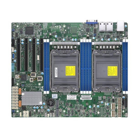
X12DPL-i6
User manual
Supermicro X12DPL-i6 User Manual
Hide thumbs
1
2
3
4
Table Of Contents
5
6
7
8
9
10
11
12
13
14
15
16
17
18
19
20
21
22
23
24
25
26
27
28
29
30
31
32
33
34
35
36
37
38
39
40
41
42
43
44
45
46
47
48
49
50
51
52
53
54
55
56
57
58
59
60
61
62
63
64
65
66
67
68
69
70
71
72
73
74
75
76
77
78
79
80
81
82
83
84
85
86
87
88
89
90
91
92
93
94
95
96
97
98
99
100
101
102
103
104
105
106
107
108
109
110
111
112
113
114
115
116
117
118
119
120
121
122
123
124
125
126
127
128
129
130
131
132
133
134
135
136
137
page
of
137
Go
/
137
Contents
Table of Contents
Troubleshooting
Bookmarks
Table of Contents
Table of Contents
Chapter 1 Introduction
Checklist
Processor and Chipset Support
Special Features
System Health Monitoring
ACPI Features
Power Supply
Serial Port
Chapter 2 Installation
Static-Sensitive Devices
Processor and Heatsink Installation
Motherboard Installation
Memory Support and Installation
Rear I/O Ports
Front Control Panel
Connectors
Jumper Settings
LED Indicators
Chapter 3 Troubleshooting
Troubleshooting Procedures
Technical Support Procedures
Frequently Asked Questions
Battery Removal and Installation
Returning Merchandise for Service
Chapter 4 UEFI BIOS
Introduction
Main Setup
Advanced Setup Configurations
Event Logs
Ipmi
Security
Boot
Save & Exit
Appendix A BIOS POST Codes
BIOS POST Codes
Appendix B Software
Microsoft Windows os Installation
Driver Installation
Superdoctor ® 5
Bmc
Logging into the BMC (Baseboard Management Controller)
Appendix C Standardized Warning Statements
Advertisement
Quick Links
1
Processor and Chipset Support
2
Memory Support and Installation
3
Connectors
Download this manual
X12DPL-
6(NT6)
i
USER'S MANUAL
Revision 1.0
Table of
Contents
Previous
Page
Next
Page
1
2
3
4
5
Advertisement
Table of Contents
Need help?
Do you have a question about the X12DPL-i6 and is the answer not in the manual?
Ask a question
Questions and answers
Related Manuals for Supermicro X12DPL-i6
Motherboard Supermicro X12DP Recovery Instructions
(30 pages)
Motherboard Supermicro X12DAi-N6 User Manual
(168 pages)
Motherboard Supermicro X12DPG-QR User Manual
(195 pages)
Motherboard Supermicro X12DPFR-AN6 User Manual
(129 pages)
Motherboard Supermicro X12DPL-NT6 User Manual
(137 pages)
Motherboard Supermicro X12DPi-N6 User Manual
(178 pages)
Motherboard Supermicro X12DPi-NT6 User Manual
(178 pages)
Motherboard Supermicro X12DPG-U6 User Manual
(129 pages)
Motherboard Supermicro X12DGO-6 User Manual
(183 pages)
Motherboard Supermicro X12DPU-6 User Manual
(186 pages)
Motherboard Supermicro X12DPT-B6 User Manual
(154 pages)
Motherboard Supermicro X12DDW-A6 User Manual
(165 pages)
Motherboard Supermicro X12DHM-6 User Manual
(160 pages)
Motherboard Supermicro X12SAE Quick Reference Manual
(25 pages)
Motherboard Supermicro X12 Series User Manual
(39 pages)
Motherboard Supermicro X12SCV-LVDS User Manual
(124 pages)
This manual is also suitable for:
X12dpl-nt6
Table of Contents
Print
Rename the bookmark
Delete bookmark?
Delete from my manuals?
Login
Sign In
OR
Sign in with Facebook
Sign in with Google
Upload manual
Upload from disk
Upload from URL


Need help?
Do you have a question about the X12DPL-i6 and is the answer not in the manual?
Questions and answers