
Related Manuals for Nexcom DTA1164W Series


Summary of Contents for Nexcom DTA1164W Series
- Page 1 NEXCOM International Co., Ltd. Network and Communication Solutions Desktop Telecom Appliance DTA1164W Series User Manual NEXCOM International Co., Ltd. www.nexcom.com Published June 2021...
-
Page 2: Table Of Contents
TPM ....................14 Knowing Your DTA1164W ..............3 Mini-PCIe Connector ..............15 Front Panel ..................3 M.2 SSD Connector ...............16 Rear Panel ...................4 M.2 5G/LTE Connector ..............17 Block Diagram ..................18 Copyright © 2021 NEXCOM International Co., Ltd. All Rights Reserved. DTA1164W Series User Manual... - Page 3 Default Configuration ................26 Entering Setup ..................26 Legends ....................26 BIOS Setup Utility ..................28 Main ....................28 Advanced ..................29 Intel RC Setup ...................38 Security .....................48 Boot ....................49 Save & Exit ..................50 Copyright © 2021 NEXCOM International Co., Ltd. All Rights Reserved. DTA1164W Series User Manual...
-
Page 4: Preface
No describes how to keep the system CE compliant. part of this manual may be reproduced, copied, translated or transmitted in any form or by any means without the prior written consent from NEXCOM Declaration of Conformity International Co., Ltd. -
Page 5: Rohs Compliance
0.1% or 1,000ppm, and Polybrominated diphenyl Ethers (PBDE) < 0.1% or 1,000ppm. In order to meet the RoHS compliant directives, NEXCOM has established an engineering and manufacturing task force in to implement the introduction of green products. The task force will ensure that we follow the standard... -
Page 6: Warranty And Rma
“NEXCOM RMA Service Form” for the RMA number apply process. ▪ If RMA goods can not be repaired, NEXCOM will return it to the customer without any charge. ▪ Customers can send back the faulty products with or without accessories (manuals, cable, etc.) and any components from the card, such as CPU... - Page 7 ESD workstation. If no such station is available, you can provide some ESD protection by wearing an antistatic wrist strap and attaching it to a metal part of the computer chassis. Copyright © 2021 NEXCOM International Co., Ltd. All Rights Reserved. DTA1164W Series User Manual...
-
Page 8: Safety Information
There is a danger of explosion if battery is incorrectly replaced. Replace only with the same or equivalent type recommended by the manufacturer. Discard used batteries according to the manufacturer’s instructions. viii Copyright © 2021 NEXCOM International Co., Ltd. All Rights Reserved. DTA1164W Series User Manual... -
Page 9: Safety Precautions
20. Use certified and rated Laser Class I for Optical Transceiver product. 13. Never open the equipment. For safety reasons, the equipment should be opened only by skilled person. Copyright © 2021 NEXCOM International Co., Ltd. All Rights Reserved. DTA1164W Series User Manual... -
Page 10: Technical Support And Assistance
Preface Technical Support and Assistance Conventions Used in this Manual 1. For the most updated information of NEXCOM products, visit NEXCOM’s Warning: website at www.nexcom.com. Information about certain situations, which if not observed, can cause personal injury. This will prevent injury to yourself 2. -
Page 11: Global Service Contact Information
Fax: +886-2-8226-7782 Shanghai, 201108, China Taichung City, 406, Taiwan, R.O.C. Email: sales@nexcom.com.tw Tel: +86-21-5278-5868 Tel: +886-4-2249-1179 www.nexcom.com.tw Fax: +86-21-3251-6358 Fax: +886-4-2249-1172 Email: sales@nexaiot.com Email: sales@nexcom.cn www.nexaiot.com www.nexcom.cn Copyright © 2021 NEXCOM International Co., Ltd. All Rights Reserved. DTA1164W Series User Manual... - Page 12 Fax: +86-23-4966-5855 Milton Keynes, Buckinghamshire Tel: +81-3-5419-7830 Email: sales@nexgol.com.cn MK8 0AB, United Kingdom Fax: +81-3-5419-7832 www.nexcobot.com/NexGOL Tel: +44-1908-267121 Email: sales@nexcom-jp.com Fax: +44-1908-262042 www.nexcom-jp.com Email: sales.uk@nexcom.eu www.nexcom.co.uk Copyright © 2021 NEXCOM International Co., Ltd. All Rights Reserved. DTA1164W Series User Manual...
-
Page 13: Package Contents
Preface Package Contents Before continuing, verify that the DTA1164W series package that you received is complete. Your DTA1164W series package should have all the items listed in the table below. Item Part Number Name 19TA0116408X0 DTA1164W 5044440031X00 Rubber Foot Set... -
Page 14: Ordering Information
Ordering Information The following below provides ordering information for DTA1164W. Barebone DTA1164W (P/N: 10TA0116408X0) Intel Denverton SoC Atom ® C3436L, BGA type 4 cores 1.30 GHz Copyright © 2021 NEXCOM International Co., Ltd. All Rights Reserved. DTA1164W Series User Manual... -
Page 15: Chapter 1: Product Introduction
▪ 5G/4G LTE supported ▪ Support M.2 SATA 2242 M-key ▪ 8 x 1GbE RJ45 (DTA1164W-A) or 6 x 1GbE RJ45 + 2 x SFP (DTA1164W) Copyright © 2021 NEXCOM International Co., Ltd. All Rights Reserved. DTA1164W Series User Manual... -
Page 16: Hardware Specifications
▪ 8 x 1GbE RJ45 cooper ports or 6 x 1GbE RJ45 copper ports + 2 x 1GbE SFP ▪ Relative humidity: 10%-90% non-condensing fiber ports ▪ 3 x Antenna holes for Wi-Fi 5 or Wi-Fi 6 Certifications ▪ CE/FCC Class B Copyright © 2021 NEXCOM International Co., Ltd. All Rights Reserved. DTA1164W Series User Manual... -
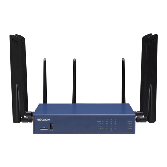
Page 17: Knowing Your Dta1164W
Two programmable LEDs (SW1 and SW2) and LEDs for power status (PWR) of the system and storage drive (SSD) activity. SIM Slot USB 3.0 LAN LED SW1/SW2/PWR/ Indicators SSD LED Indicators Copyright © 2021 NEXCOM International Co., Ltd. All Rights Reserved. DTA1164W Series User Manual... -
Page 18: Rear Panel
Press to power-on or power-off the system. 12V DC LAN2 to LAN7 LAN0 to LAN1 Power Input Copper Ports SFP Ports Button 54V DC Input RJ45 Console (For optional PoE) USB 3.0 Copyright © 2021 NEXCOM International Co., Ltd. All Rights Reserved. DTA1164W Series User Manual... -
Page 19: Chapter 2: Jumpers And Connectors
Static electricity can damage many of the electronic ▪ Use correct screws and do not over tighten screws. components. Humid environments tend to have less static electricity than Copyright © 2021 NEXCOM International Co., Ltd. All Rights Reserved. DTA1164W Series User Manual... -
Page 20: Jumper Settings
(on) and open (off). Two-Pin Jumpers: Open (Left) and Short (Right) Three-Pin Jumpers: Pins 1 and 2 are Short Copyright © 2021 NEXCOM International Co., Ltd. All Rights Reserved. DTA1164W Series User Manual... -
Page 21: Locations Of The Jumpers And Connectors
Chapter 2: Jumpers and Connectors Locations of the Jumpers and Connectors The figure below shows the location of the jumpers and connectors. JTPM1 LAN1 LAN2 Copyright © 2021 NEXCOM International Co., Ltd. All Rights Reserved. DTA1164W Series User Manual... -
Page 22: Jumpers
PMC Clear Connector type: 1x3 3-pin header Connector type: 1x3 3-pin header Connector location: JP2 Connector location: JP3 Function Function Normal Normal Clear CMOS Clear PMC Copyright © 2021 NEXCOM International Co., Ltd. All Rights Reserved. DTA1164W Series User Manual... -
Page 23: Me Recover Mode
Chapter 2: Jumpers and Connectors ME Recover Mode Connector type: 1x2 2-pin header Connector location: JP5 Function Normal (Default) ME Recover Mode Copyright © 2021 NEXCOM International Co., Ltd. All Rights Reserved. DTA1164W Series User Manual... -
Page 24: Connector Pin Definitions
Chapter 2: Jumpers and Connectors Connector Pin Definitions External I/O Interfaces 12V DC Input 54V DC Input (For optional PoE) Connector location: CN2 Connector location: CN3 Definition Definition DC_IN Copyright © 2021 NEXCOM International Co., Ltd. All Rights Reserved. DTA1164W Series User Manual... -
Page 25: Lan0 Sfp Port
Definition Definition P_LAN2_MDI0P P_LAN2_MDI0N P_LAN1_MDI0P P_LAN1_MDI0N P_LAN2_MDI1P P_LAN2_MDI1N P_LAN1_MDI1P P_LAN1_MDI1N P_LAN2_MDI2P P_LAN2_MDI2N P_LAN1_MDI2P P_LAN1_MDI2N P_LAN2_MDI3P P_LAN2_MDI3N P_LAN1_MDI3P P_LAN1_MDI3N P3V3 PORT2_ACT_N P3V3 PORT1_ACT_N PORT2_L100_N PORT2_L1000_N PORT1_L100_N PORT1_L1000_N Copyright © 2021 NEXCOM International Co., Ltd. All Rights Reserved. DTA1164W Series User Manual... -
Page 26: Power Button
USB 3.0 Port Connector location: SW1 Connector type: USB 3.0 port, Type A Connector location: CN4 Definition Definition Definition USB2_DN PWRBTN#_IN USB2_DP USB3_RX_DN USB3_RX_DP USB3_TX_DN USB3_TX_DP GND_chassis GND_chassis Copyright © 2021 NEXCOM International Co., Ltd. All Rights Reserved. DTA1164W Series User Manual... -
Page 27: Internal Connectors
MCU Reset Connector type: 1x4 4-pin wafer Connector type: 1x4 4-pin header Connector location: CN1 Connector location: J1 Definition Definition Definition Definition P12V P3V_MCU SWIM TACH MCU_RESET Copyright © 2021 NEXCOM International Co., Ltd. All Rights Reserved. DTA1164W Series User Manual... -
Page 28: Mcu
Connector type: 2x7 14-pin header Connector location: J2 Connector location: JTPM1 Definition Definition Definition Definition LPC_CLK P3V_MCU UART_TX UART_RX LPC_FRAME TPM_LAD2 TPM_LRESET TPM_LAD1 TPM_LAD3 TPM_LAD0 SERIRQ_TPM 3.3V Copyright © 2021 NEXCOM International Co., Ltd. All Rights Reserved. DTA1164W Series User Manual... -
Page 29: Mini-Pcie Connector
WAKE# 3.3V SMB_CLK PCIE_TX_D- SMB_DATA CLKREQ# PCIE_TX_D+ USB_D- CLK- USB_D+ CLK+ 3.3V(Reserved) 3.3V(Reserved) LED_WWAN# LED_WLAN# W_DISABLE# 3.3V(Reserved) LED_WPAN# PERST# 3.3V(Reserved) PCIE_RX_D- 3.3V 3.3V(Reserved) PCIE_RX_D+ 3.3V(Reserved) 3.3V Copyright © 2021 NEXCOM International Co., Ltd. All Rights Reserved. DTA1164W Series User Manual... -
Page 30: M.2 Ssd Connector
Connector location: CN6 Definition Definition Definition Definition 3.3V SATA_RX_D+ 3.3V SATA_RX_D- SATA_TX_D- SATA_TX_D+ PERST# 3.3V CLKREQ# 3.3V CLK_D- CLK_D+ 3.3V 3.3V SUSCLK 3.3V 3.3V 3.3V DEVSLP Copyright © 2021 NEXCOM International Co., Ltd. All Rights Reserved. DTA1164W Series User Manual... -
Page 31: M.2 5G/Lte Connector
CLK+ 5G_COLAY20 CONGIF0 5G_COLAY22 WAN_WAKE# 5G_COLAY24 5G_DPR W_DISABLE2# 5G_COLAY28 SIM_DETECT USB3_RX- SIM_RST RESET# 5G_COLAY68 USB3_RX+ SIM_CLK CONFIG1 3.3V SIM_DATA 3.3V USB3_TX- SIM_PWR 3.3V USB3_TX+ 5G_COLAY38 CONFIG2 Copyright © 2021 NEXCOM International Co., Ltd. All Rights Reserved. DTA1164W Series User Manual... -
Page 32: Block Diagram
SFP/RJ45 PCIE C3558 Soc USB3.0 +Console I211-AT RJ45 With POE NCT6683 I211-AT RJ45 With POE Header SGMII Smbus Marvell Microsemi 88E1543 PD69104 RJ45 GbE 4 Ports Copyright © 2021 NEXCOM International Co., Ltd. All Rights Reserved. DTA1164W Series User Manual... -
Page 33: Chapter 3: System Setup
1. The screws on the bottom and sides of the cover are used to secure the cover to the chassis. Remove these screws and put them in a safe place for later use. Screws on the sides Screws on the bottom Copyright © 2021 NEXCOM International Co., Ltd. All Rights Reserved. DTA1164W Series User Manual... - Page 34 To prevent this, place the cover past ahead of the acetate tape before sliding it back. Refer to the images below for more information. Correct way Acetate tape Incorrect way Copyright © 2021 NEXCOM International Co., Ltd. All Rights Reserved. DTA1164W Series User Manual...
-
Page 35: Installing A So-Dimm Memory Module
The gold-plated connector on the edge of the module will almost completely disappear inside the socket. Memory Module SO-DIMM Socket Copyright © 2021 NEXCOM International Co., Ltd. All Rights Reserved. DTA1164W Series User Manual... - Page 36 3. Push the module down until the clips on both sides of the socket lock into position. You will hear a distinctive “click” sound, indicating the module is correctly locked into position. Copyright © 2021 NEXCOM International Co., Ltd. All Rights Reserved. DTA1164W Series User Manual...
-
Page 37: Installing Both The M.2 And Wi-Fi Module
Push the M.2 module down and fasten an M.2 mounting screw into the mounting hole to secure the module. M.2 Slot M.2 Mounting M.2 Slot Screw Copyright © 2021 NEXCOM International Co., Ltd. All Rights Reserved. DTA1164W Series User Manual... - Page 38 Push the Wi-Fi module down and fasten a Wi-Fi mounting screw into the mounting hole to secure the module. Wi-Fi Slot Wi-Fi Mounting Screw Copyright © 2021 NEXCOM International Co., Ltd. All Rights Reserved. DTA1164W Series User Manual...
-
Page 39: Chapter 4: Bios Setup
BIOS is updated in the future. second, to make settings appropriate for the way you use the computer. To check for the latest updates and revisions, visit the NEXCOM website at When to Configure the BIOS www.nexcom.com.tw. -
Page 40: Default Configuration
Powering on the computer and immediately pressing allows you to enter Setup. Load optimized default values. Saves and exits the Setup program. Press <Enter> to enter the highlighted sub-menu Copyright © 2021 NEXCOM International Co., Ltd. All Rights Reserved. DTA1164W Series User Manual... - Page 41 When “” appears on the left of a particular field, it indicates that a submenu which contains additional options are available for that field. To display the submenu, move the highlight to that field and press Copyright © 2021 NEXCOM International Co., Ltd. All Rights Reserved. DTA1164W Series User Manual...
-
Page 42: Bios Setup Utility
+/-: Change Opt. F1: General Help F2: Previous Values F3: Optimized Defaults F4: Save & Exit ESC: Exit Version 2.19.1266. Copyright (C) 2021 American Megatrends, Inc. Copyright © 2021 NEXCOM International Co., Ltd. All Rights Reserved. DTA1164W Series User Manual... -
Page 43: Advanced
+/-: Change Opt. F1: General Help F2: Previous Values F3: Optimized Defaults F4: Save & Exit ESC: Exit Version 2.19.1266. Copyright (C) 2021 American Megatrends, Inc. Copyright © 2021 NEXCOM International Co., Ltd. All Rights Reserved. DTA1164W Series User Manual... - Page 44 Displays the Super I/O chip used on the board. Security Device. TCG EFI protocol and INT1A interface will not be available. Serial Port 1 Configuration Configures the IO/IRQ settings of serial port 1. Copyright © 2021 NEXCOM International Co., Ltd. All Rights Reserved. DTA1164W Series User Manual...
- Page 45 Selects an optimal setting for the Super IO device. Detects and displays the fan speed of CN1. CPU VCORE to P12V Detects and displays the output voltages. Copyright © 2021 NEXCOM International Co., Ltd. All Rights Reserved. DTA1164W Series User Manual...
- Page 46 Bits Per Second available. Selects the serial port transmission speed. The speed must match the other side. Long or noisy lines may require a lower speed. Copyright © 2021 NEXCOM International Co., Ltd. All Rights Reserved. DTA1164W Series User Manual...
- Page 47 Enables or disables the VGA palette registers snooping. Putty Keypad Selects the Putty keyboard emulation type. PERR# Generation Enables or disables the PCI device to generate PERR#. Copyright © 2021 NEXCOM International Co., Ltd. All Rights Reserved. DTA1164W Series User Manual...
- Page 48 When this function is enabled, it allows a device to use 8-bit tag field as a request. No Snoop Enables or disables the PCI Express device’s no snoop option. Copyright © 2021 NEXCOM International Co., Ltd. All Rights Reserved. DTA1164W Series User Manual...
- Page 49 Selects the timeout period of link training in microseconds. Completion Timeout Configures the completion timeout value. Unpopulated Links Enables or disables unpopulated PCI Express links. Target Link Speed Configures the PCIe link speed. Copyright © 2021 NEXCOM International Co., Ltd. All Rights Reserved. DTA1164W Series User Manual...
- Page 50 GA20 can be disabled using BIOS services. Always Do not allow disabling of GA20; this option is useful when any RT code is executed above 1MB. Copyright © 2021 NEXCOM International Co., Ltd. All Rights Reserved. DTA1164W Series User Manual...
- Page 51 Disable Keeps USB devices available only for EFI applications. XHCI Hand-off This is a workaround for OSes that does not support XHCI hand-off. The XHCI ownership change should be claimed by the XHCI driver. Copyright © 2021 NEXCOM International Co., Ltd. All Rights Reserved. DTA1164W Series User Manual...
-
Page 52: Intel Rc Setup
ESC: Exit Version 2.19.1266. Copyright (C) 2021 American Megatrends, Inc. Relax Security Config Enables or disables the security configuration to be able to use BIOS update tools. Copyright © 2021 NEXCOM International Co., Ltd. All Rights Reserved. DTA1164W Series User Manual... - Page 53 Set this field to Disable when using Windows XP. Set this field to Enable when using legacy operating systems so that the system will boot even when it doesn’t support CPUs with extended CPUID function. Copyright © 2021 NEXCOM International Co., Ltd. All Rights Reserved. DTA1164W Series User Manual...
- Page 54 Version 2.19.1266. Copyright (C) 2021 American Megatrends, Inc. Version 2.19.1266. Copyright (C) 2021 American Megatrends, Inc. Memory Frequency VT-d Configures the DDR memory frequency. Enables or disables Intel ® VT-d technology. Copyright © 2021 NEXCOM International Co., Ltd. All Rights Reserved. DTA1164W Series User Manual...
- Page 55 State After G3 SATA 1 Configures which state to use when power is re-applied after a power Enters the sub-menu of SATA 1 configuration. failure (G3 state). Copyright © 2021 NEXCOM International Co., Ltd. All Rights Reserved. DTA1164W Series User Manual...
- Page 56 Enables or disables the SATA controller if supported by the current CPU SKU. Enables or disables the SATA controller port if supported by the current CPU SKU. Speed limit Configures the speed limit of the SATA controller. Copyright © 2021 NEXCOM International Co., Ltd. All Rights Reserved. DTA1164W Series User Manual...
- Page 57 Enters the sub-menu for USB super speed configuration. Enters the sub-menu for port 0 and port 1 configuration. USB HS Configuration Enters the sub-menu for USB high speed configuration. Copyright © 2021 NEXCOM International Co., Ltd. All Rights Reserved. DTA1164W Series User Manual...
- Page 58 USB devices plugged into the connector will not be detected disabled, any USB devices plugged into the connector will not be detected by BIOS or OS. by BIOS or OS. Copyright © 2021 NEXCOM International Co., Ltd. All Rights Reserved. DTA1164W Series User Manual...
- Page 59 Enables or disables the USB Physical Connector (physical port). Once disabled, any USB devices plugged into the connector will not be detected by BIOS or OS. Copyright © 2021 NEXCOM International Co., Ltd. All Rights Reserved. DTA1164W Series User Manual...
- Page 60 USB devices plugged into the connector will not be detected disabled, any USB devices plugged into the connector will not be detected by BIOS or OS. by BIOS or OS. Copyright © 2021 NEXCOM International Co., Ltd. All Rights Reserved. DTA1164W Series User Manual...
- Page 61 Set IQAT FUSECTL Enables or disables the configuration of IQAT FUSECTL register. Set 64B MRR/MPL Enables or disables the configuration of 64B MRR/MPL in IQAT DevCTL register. Copyright © 2021 NEXCOM International Co., Ltd. All Rights Reserved. DTA1164W Series User Manual...
-
Page 62: Security
F3: Optimized Defaults F4: Save & Exit ESC: Exit Version 2.19.1266. Copyright (C) 2021 American Megatrends, Inc. Administrator Password Select this to reconfigure the administrator’s password. Copyright © 2021 NEXCOM International Co., Ltd. All Rights Reserved. DTA1164W Series User Manual... -
Page 63: Boot
NumLock on wherein the function of the numeric keypad is the number keys. When set to Off, the function of the numeric keypad is the arrow keys. Copyright © 2021 NEXCOM International Co., Ltd. All Rights Reserved. DTA1164W Series User Manual... -
Page 64: Save & Exit
<Enter>. You may be prompted to confirm again before exiting. Restore Defaults To restore the BIOS to default settings, select this field then press <Enter>. A dialog box will appear. Confirm by selecting Yes. Copyright © 2021 NEXCOM International Co., Ltd. All Rights Reserved. DTA1164W Series User Manual...
Need help?
Do you have a question about the DTA1164W Series and is the answer not in the manual?
Questions and answers