Table of Contents
Advertisement
Advertisement
Table of Contents

Related Manuals for Autel MaxiCharger DC Fast


Summary of Contents for Autel MaxiCharger DC Fast
- Page 2 All information, specifications and illustrations in this manual are based on the latest information available at the time of printing. Autel reserves the right to make changes at any time without notice. While information of this manual has been carefully checked for accuracy, no guarantee is given for the completeness and correctness of the contents, including but not limited to the product specifications, functions, and illustrations.
-
Page 3: Table Of Contents
CONTENTS USING THIS MANUAL ..................... 1 ........................1 ONVENTIONS Bold Text ........................ 1 Notes ........................1 Hyperlinks ......................1 Procedures ......................2 ........................3 ERMINOLOGY SAFETY ..........................4 ......................4 AFETY ARNINGS ....................4 WNER ESPONSIBILITIES ................5 NSTALLATION NGINEER UALIFICATIONS ...................... - Page 4 ....................... 21 NSTALLATION OOLS INSTALLATION ......................22 .................. 23 REPARING THE NSTALLATION Location Requirements ..................24 Preparing the Foundation ..................27 ....................32 NSTALLING THE ABINET ............35 REPARING FOR LECTRICAL ABLE NSTALLATION ......................36 LECTRICAL IRING Connecting the PE Wire ..................36 Connecting the Enclosure to the earth ..............
- Page 5 Authorization Failure .................... 52 Charging Start Failure ..................52 Charging Failure ....................52 ..................52 NERGIZING THE HARGER .................. 53 ENERGIZING THE HARGER Measuring the AC Voltage ................... 53 Measuring the DC Voltage ................... 54 ....................55 EMOVING ONDENSATION ................56 OCAL ERVICE ORTAL...
- Page 6 ................75 OWER ONSUMPTION PECIFICATIONS .............. 76 NPUT HORT IRCUIT URRENT PECIFICATIONS...
-
Page 7: Using This Manual
Using This Manual This manual contains device usage instructions. Some illustrations shown in this manual may contain modules and optional equipment that are not included in your system. Contact your sales representative for availability of other modules and optional tools or accessories. The document is intended for these groups: Owner of the MaxiCharger (see Owner... -
Page 8: Procedures
Procedures An arrow icon indicates a procedure. For example: To reset the MaxiCharger Ensure that the situation is safe again. Turn the Emergency Stop button clockwise to release it. The MaxiCharger will start and the error message will disappear from the touchscreen. -
Page 9: Terminology
Terminology Table 1-1 Terminology Term Definition Alternating current Combined Charging System; a standard charging method for electric vehicles Charging Control Unit; a control unit used to communicate with BMS, and control the power delivery to the EV Abbreviation of CHArge de Move; a standard charging CHAdeMO method for electric vehicles Direct current... -
Page 10: Safety
Safety Safety Warnings Disconnect the power supply to the MaxiCharger during the entire installation procedure. The load capacity of the grid must meet the requirements of the MaxiCharger. Connect the MaxiCharger to a grounded, metal, permanent wiring system. Otherwise, use the equipment-grounding conductor with the circuit conductors and connect it to the equipment grounding terminal or lead on the product. -
Page 11: Installation Engineer Qualifications
Make sure that all employees and third parties are qualified in accordance with the applicable local rules to perform their work. Make sure that there is sufficient space around the MaxiCharger to safely do maintenance and installation work. Identify a site operator who is responsible for the safe operation of the MaxiCharger and for the coordination of all work, if the owner does not do these tasks. -
Page 12: Disposal Instructions
These measures may include firewalls, authentication methods, data encryption, anti-virus programs, etc. Autel is not liable for damages and/or losses resulting from security breaches. -
Page 13: General Introduction
General Introduction The Autel MaxiCharger is designed to charge an electric vehicle (hereinafter called EV). Our chargers provide you with safe, reliable, fast, and smart charging solutions. The MaxiCharger is intended for the DC charging of EVs and is intended for both indoor and outdoor use in fleets, highway rest stops, commercial parking garages, and other locations. -
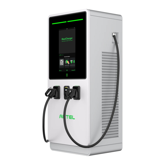
Page 14: Product Overview
Product Overview Figure 3-1 MaxiCharger Overview, Outside Main Cabinet Eye Bolt — for equipment movement, loading and unloading... - Page 15 20. Base NOTE Autel can deliver the MaxiCharger with different payment terminals. The available options vary depending on the region and country where the MaxiCharger is installed. If you need more information about different options for the payment terminals, consult Autel...
- Page 16 Table 3-1 Status Indicator Key Charging Status Color Meaning Standby Mode Solid Green The connector is available. connected EV Connected Solid White MaxiCharger. Illuminating Green in Indicates how much of your EV is Charging Turn charged. An EV is fully charged or has Charge Complete Flashing Green stopped charging.
- Page 17 Figure 3-2 MaxiCharger Overview, Inside A. Main Breaker — connects/disconnects the charging module B. AC Filter (optional)
-
Page 18: Working Principle Diagram
C. SPD Breaker D. SPD E. Auxiliary AC Main Fuse F. Auxiliary RCCB G. Cable Gland Plate H. Charging Module I. Heater Circuit Fuse J. Contactor Circuit Fuse K. 48V Auxiliary AC Fuse L. 24V Auxiliary AC Fuse M. PE Busbar — connects the PE cable Working Principle Diagram Figure 3-3 Working Principle View NOTE... -
Page 19: Local Service Portal
OCPP IP *******.*******.** OCPP-URL address ********** Port number OCPP encryption method Country code Network selection auto/wifi/4g Supplier Autel Control board SN C06G120******** MAC address ba:9f:aa:8c:**:** Password 000000 Connection ID 0: Connectors 1 and 2 initialization Charger configuration 120:120kW model MGR IP *******.*******.**... -
Page 20: Cloud Service Portal
Rated Power 120kW Rated Voltage 1000V Maximum current 200A Set Current 200A Max Power 120kW Cloud Service Portal Autel provides a set of cloud-based tools to commission, monitor, and troubleshoot the MaxiCharger. For more information, contact your Autel e-Mobility representative... -
Page 21: Preparation
Preparation The MaxiCharger is delivered in close proximity to the site. However, the owner is responsible for moving the MaxiCharger to its final location. If the MaxiCharger needs to be safely stored before installation, follow the conditions listed in Table 9-2 Operating Conditions. -
Page 22: Unpacking
Figure 4-1 Tilt and Inversion Indicators If the shock watch appears red, contact Autel customer service and the delivery personnel, and then inspect the product for any damage. Do not accept the delivery until the inspection is complete and no damage is found. -
Page 23: Moving The Cabinet To The Site
Moving the Cabinet to the Site There are two ways to move the cabinet to the installation site: Hoist Forklift WARNING Follow the safety instructions that apply to the hoisting equipment or forklift to move the cabinet. Take into account the dimensions, mass, and center of gravity of the MaxiCharger. CAUTION ... -
Page 24: Forklifting The Cabinet
Forklifting the Cabinet To forklift the cabinet Make sure the forks (A) of the forklift truck in the gaps go through the gaps in the side of the pallet. Move the cabinet to the construction site. Figure 4-3 Transporting the Cabinet by Forklift... -
Page 25: Packing List
Packing List Table 4-1 Packing List Expansion Bolt MaxiCharger (M16 x 150) 4 PCS Washer (10) Washer (10) 5 PCS 10 PCS (for 120 kW only) (for 240 kW only) Spring Washer Hexagonal Nut (10) (M10) 5 PCS 5 PCS (for 240 kW only) Bolt (M8 x 25) Packing List... - Page 26 Drilling Template Drilling Template (for 120 kW only) (for 240 kW only)
-
Page 27: Installation Tools
Installation Tools Table 4-2 Installation Tools Tool Specification Philips Screwdriver Size: PH2 Slot Screwdriver Size: 2.5 and 4.5 M8 (13 mm) Open Spanner M10 (15 mm) M16 (24 mm) M8 (13 mm) Ratchet Spanner with M10 (15 mm) Socket and Extension ... -
Page 28: Installation
Installation IMPORTANT The installation should be performed by an installation engineer. Make sure all required permits are granted form local authorities. Make sure the AC input cable is available. Make sure the tools for installation are prepared, see Table 4-2 Installation Tools. -
Page 29: Preparing The Installation Site
Preparing the Installation Site An installation site design is a prerequisite for determining conduit and wiring requirements from the panel to proposed parking spaces, as well as for measuring cellular signal strength and identifying suitable locations for any necessary cellular signal booster equipment. -
Page 30: Location Requirements
Location Requirements An installation space of 2420 x 1950 mm (for MaxiCharger DC 120) or 2620 x 2050 mm (for MaxiCharger DC 240) is required in order to ensure normal operation and proper airflow around the unit. The space is calculated as follows: Figure 5-1 Location Requirements A. - Page 31 Table 5-1 Location Requirements (for MaxiCharger DC 120) Specification Parameter 32.28 31.5 31.5 23.62 19.69 33.46 Table 5-2 Location Requirements (for MaxiCharger DC 240) Specification Parameter 32.28 35.43 35.43 27.56 19.69 33.46 Choose a site where the charging cable is of sufficient length to be connected to the EV charge port.
- Page 32 EVs. Diagonal stall parking is not advised. NOTE While Autel tests the MaxiCharger with a majority of modern vehicles, we cannot guarantee the port locations of future vehicles and cannot warrant the configurations proposed will work for all vehicles.
-
Page 33: Preparing The Foundation
Preparing the Foundation To prepare a casted foundation Dig a hole based on the foundation size. IMPORTANT The minimum sizes of the hole for MaxiCharger DC 120 and MaxiCharger DC 240 are 820 x 640 x 500 mm and 820 x 740 x 500 mm, respectively. ... - Page 34 Table 5-3 Digging a Hole Specifications Specification Parameter MaxiCharger DC 120 MaxiCharger DC 240 640 mm 25.2 in 740 mm 29.13 in 820 mm 32.28 in 820 mm 32.28 in 500 mm 19.68 in 500 mm 19.68 in Pour the concrete into the hole. Make sure that the cable duct/conduit is in the correct position.
- Page 35 Specification Parameter MaxiCharger DC 120 MaxiCharger DC 240 500 mm 19.69 in 500 mm 19.69 in 150 mm 5.9 in 150 mm 5.9 in 100 mm 3.94 in 100 mm 3.94 in 350 mm 13.78 in 350 mm 13.78 in NOTE ...
- Page 36 Place the drilling template provided in the package onto the foundation, aligning with the marked area (C). Mark the four drilling holes (D) and remove the drilling template. Drill four holes with over 110 mm in depth and 20 mm in diameter in the foundation at the marked positions (D) for inserting the expansion bolts into the...
- Page 37 Table 5-6 Drilling Holes Specifications Specification Parameter MaxiCharger DC 120 MaxiCharger DC 240 820 mm 32.28 in 820 mm 32.28 in 95 mm 3.74 in 95 mm 3.74 in 630 mm 24.80 in 630 mm 24.80 in 132 mm 5.51 in 140 mm 5.51 in 220 mm...
-
Page 38: Installing The Cabinet
Installing the Cabinet To install the cabinet Remove the front and rear base covers (A) using a screwdriver. Figure 5-5 Removing the Base Covers Open the front door of the cabinet. Remove the M6 screws (C) and the insulating barrier (B) from the cabinet. (Reinstall the insulating barrier when the commissioning procedure is complete.) Figure 5-6 Removing the Insulating Barrier... - Page 39 Loosen the fasteners (D) on the cable gland plate to remove the plate and close the door. Figure 5-7 Loosening the Fasteners Remove the hexagonal nuts (E), spring washers (F), washers (G1), bolt (H), and washers (G2). Figure 5-8 Removing the Cabinet from the Pallet Discard the pallet.
- Page 40 Tighten the bolts. Figure 5-9 Tightening the Bolts...
-
Page 41: Preparing For Electrical Cable Installation
Preparing for Electrical Cable Installation To prepare for cable installation Reinstall the cable gland plate. CAUTION If the cable gland for the Ethernet cable is not used, make sure that the cable gland is closed and sealed. Guide the AC input wires (C) and Ethernet cables (E) through the cable gland plate as instructed in the following figure and tighten the four fasteners to secure the cable gland plate. -
Page 42: Electrical Wiring
Electrical Wiring Connecting the PE Wire To connect the PE wire Cut the PE wire (C) of the power cable to the correct length to reach the PE busbar (B). Use the wire stripper to remove 20 mm of the insulation from the end of the wires (or strip the wire if necessary). -
Page 43: Connecting The Enclosure To The Earth
Figure 5-12 Connecting the PE Wire Connecting the Enclosure to the earth To connect the enclosure to the earth Connect the earthing conductor to the pin of the enclosure. Connect the earthing conductor to the earthing electrode. Figure 5-13 Connecting the Enclosure to the earth... -
Page 44: Connecting The Ac Input Wires
Connecting the AC Input Wires To connect the AC input wires Cut the wires N, L1, L2, and L3 to the correct length to reach the connectors on the AC fuse copper busbar. Use the wire stripper to remove 20 mm of the insulation from the end of the wires (or strip the wire if necessary). -
Page 45: Connecting The Ethernet Cable
seal it using duct seal. If needed, connect two AC input wires of the same type to each connector as shown below: Figure 5-15 Connecting the Two AC Input Wires Connecting the Ethernet Cable Connect the Ethernet cable to one of the RJ45 ports. Figure 5-16 Connecting the Ethernet Cable... -
Page 46: Installing Sim Card
Installing SIM Card Press the button (A) to eject the SIM card tray. Insert the SIM card into the tray. Ensure the card is placed correctly. Push the card tray into the slot. Figure 5-17 Installing SIM Card... -
Page 47: Installing The Charging Modules
Installing the Charging Modules To install the charging modules Figure 5-18 Installing the Charging Modules (for MaxiCharger DC 120) Slowly push the module into the slot. Table 5-7 Charging Module Installation Specifications (for MaxiCharger DC 120) Rated Number of Type Location Power... - Page 48 Figure 5-19 Installing the Charging Modules (for MaxiCharger DC 240) Table 5-8 Charging Module Installation Specifications (for MaxiCharger DC 240) Number of Type Rated Power Location Modules MaxiCharger DC 160 160 kW 8 PCS 1, 2, 3, 4, 7, 8, 9, 10 (EF160A3001) MaxiCharger DC 180 180 kW...
- Page 49 IMPORTANT Install the sealing boards into the slots where the charging modules are not inserted. Figure 5-20 Sealing Board Figure 5-21 Tightening the Screws Tightening the screws to the torque of 1.2 N·m (10.6 lb·in) to secure the modules. After the installation is complete, set the hardware address. For details, contact manufacturer certified installation engineer.
-
Page 50: Installing The External Residual-Current Device
Installing the External Residual-current Device The MaxiCharger includes a Type A RCD integrated in the main breaker, and a RCCB for the auxiliary path. The use of external RCD may cause a nuisance tripping during transient conditions such as when the AC contactor turns on at the start of charging. If an external residual-current device cannot be avoided due to local regulations, the in-rush current should be considered when selecting the device. -
Page 51: Operation
Use the multimeter to check the circuit connections among L1, L2, L3, N, and PE. If short circuit occurs, contact Autel technical support; Otherwise, reinstall the insulating barrier. Make sure that the RCCB and MCCB stay in the OFF position. -
Page 52: Emergency Stop
CAUTION To prevent damage to the MaxiCharger, remove condensation before use. Emergency Stop In any emergency situation, push the Emergency Stop button. The MaxiCharger stops all charging processes and the touchscreen displays a message as shown in the following figure: Figure 6-1 Fault Message Screen ... -
Page 53: Charging Procedure
Charging Procedure Screen Layout Figure 6-2 Standby Screen ① Advertisement page — can be displayed on a full screen and is omitted in the following sample figures ② Connector options — tap to view connector information ③ Home button, cost information, and language options ④... -
Page 54: Authorization
If the screen displays an error message, DO NOT use the MaxiCharger. Contact Autel Technical Support. When the Authorization Screen appears, you can use any of the following methods to start a charge session. -
Page 55: Start Charging
Start Charging After authorization, the MaxiCharger will set up communication with your EV and necessary safety tests will be performed. Following the safety tests, the charge session will start automatically. Figure 6-4 Start Charging Screen... -
Page 56: Charging
Charging You will be informed of the progress during charging. Information about the charging duration, volume, cost, and power will appear on the Charging Screen. Tap the right arrow button on the right to view more information about the charging status, including SoC (State of Charge), current, and voltage. -
Page 57: Stop Charging
Normally, you have to authorize again to finish charging, using the same authentication method as was used to start: QR code: Tap the Stop button on the Charging Screen of the Autel Charge app. RFID card: Put the RFID card on the card reader again to finish charging. -
Page 58: Charging Errors
If an error occurs during charging, the Charging Failure screen will appear. The cause and possible solution(s) will display on the screen. Follow the on-screen instructions to resolve the problem, or contact your local dealer or Autel Technical Support. Energizing the MaxiCharger ... -
Page 59: De-Energizing The Maxicharger
De-energizing the MaxiCharger To de-energize the MaxiCharger Set the upstream breaker which provides the power to the MaxiCharger to OFF and lock it. Make sure that this breaker stays in the OFF position during the procedure. Open the front door. Measure the AC voltage by referring to Measuring the AC Voltage. -
Page 60: Measuring The Dc Voltage
Measuring the DC Voltage Remove the insulating barrier and use a voltage tester to measure the DC voltage between the output terminals, make sure that all the measured voltages are 0 volts. Power module group output 1 — (A) to power module group output 1+ (B) ... -
Page 61: Removing Condensation
Removing Condensation NOTE If the MaxiCharger is off for more than two hours, condensation can occur. To remove condensation from the cabinet Open the front door. Set the main breaker from the ON to the OFF position. Energize the MaxiCharger. Close the door. -
Page 62: Local Service Portal Operations
To set the OCPP parameters Tap the upper-left corner of the screen. Tap Device Maintenance. Enter the default password (contact Autel customer service to obtain the password). Tap Set Parameters. Wait for the system to load the data. This can take a few seconds. -
Page 63: Maintenance
Maintenance Routine Maintenance Routine maintenance can keep the MaxiCharger in safe and stable state. Clean the cabinet every quarter: tighten the screws and bolts of key parts, and check whether the wire connection of the MaxiCharger’s connector is burned out. If any abnormality is found, replace the parts promptly. -
Page 64: Cleaning The Cabinet
Autel technical support or your local dealer. Do not use the MaxiCharger until the repair is complete. Locate the RCCB, and press the Test button of the device to start test. Pass: The auxiliary power supply stops working when the RCCB is set to the OFF position. - Page 65 Do not apply high-pressure water jets and avoid water leaking into the MaxiCharger. Make sure that the inside of the MaxiCharger is dry during cleaning. Do not use caustic solvents, sprays, solvents or abrasives. The MaxiCharger is equipped with an air inlet filter and an air outlet filter with a large mesh area to prevent the electronic components from being damaged by dust.
- Page 66 To clean or replace the air outlet filter Before cleaning and replacing, be sure to stop all charging processes, disconnect the external power supply, and perform the power-off protection. Open the left-side door of the MaxiCharger. When the cabinet door is open, the MaxiCharger should not be directly exposed to wind and rain.
-
Page 67: Inspection And Maintenance
System self-check for abnormality daily. If any operation abnormality is found, contact your local dealer or Autel technical support promptly. Autel service engineers can check logs, update configurations and programs, and provide remote maintenance services, such as remote management, diagnosis, configuration, and upgrades. -
Page 68: Maintenance Schedule
Maintenance Schedule Table 7-1 Maintenance Schedule Item Frequency Actions Check for cracks or ruptures on the Connector Every 3 months connector. Check for cracks or ruptures on the Input Cable Every 3 months cable. Inlet Air Filter Annually Replace the inlet air filter. Outlet Air Filter Annually Replace the outlet air filter. -
Page 69: Troubleshooting And Service
Troubleshooting Try to find a solution for the problem with the aid of the information in this document. If you cannot find a solution for the problem, contact your local Autel representative or Autel Technical Support. Table 8-1 Troubleshooting Details... - Page 70 Possible Issue Solution Handler Cause Autel Technical Support Customer Technical Ensure that the network Support/ Cellular SIM card is properly network failure Autel installed. Technical Support QR Code Scanning Failure Customer Technical Support/ Local network Check local network failure connection.
-
Page 71: Service
Technical support. Support Service If you cannot find solutions to your problems with the aid from the table above, please contact Autel Technical Support. AUTEL Europe Phone: +49(0)89 540299608 (Monday–Friday, 9:00 AM–6:00 PM Berlin Time) Email: evsales.eu@autel.com; evsupport.eu@autel.com Address: Landsberger Str. 408, 4. OG, 81241 Munich, Germany... -
Page 72: Technical Specifications
Technical Specifications General Specifications Table 9-1 Product Specifications Parameter Description IEC 61851-1 IEC 61851-23 Compliance and Safety IEC 61851-21-2 IEC 61000 IP Rating IP54 IK Rating IK10 Short Circuit Current Rating 35 kA Class A ... - Page 73 Parameter Description Input AC Power Connection 3P + N + PE Input Voltage Range 400 V AC ±10% Power Factor at Full Load >= 0.98 Peak Efficiency >= 96% Total Harmonic Distortion <= 5% (current / > 50% load) Table 9-2 Operating Conditions Parameter Specification ...
-
Page 74: Packaging Specifications
Packaging Specifications Table 9-3 General Dimensions Specification Parameter MaxiCharger DC 120 MaxiCharger DC 240 Width of the Cabinet 820 mm 32.28 in 820 mm 32.28 in Depth of the Cabinet 600 mm 23.62 in 700 mm 27.56 in Height of the Cabinet 1950 mm 76.77 in 1950 mm... -
Page 75: Installation Specifications
Installation Specifications Figure 9-1 Center of Gravity Table 9-5 Center of Gravity Specifications Specification Parameter MaxiCharger DC 120 MaxiCharger DC 240 400 mm 15.75 in 400 mm 15.75 in 330 mm 12.99 in 300 mm 11.81 in 840 mm 33.07 in 840 mm 33.07 in... - Page 76 Figure 9-2 Operable Element Specifications Table 9-6 Operable Element Specifications Specification Parameter Description Highest user operable element of MaxiCharger 1350 53.15 Lowest user operable element of MaxiCharger 30.16 Foundation height of MaxiCharger 5.91...
-
Page 77: Communication Interface Specifications
Table 9-7 Items Included in the Delivery Item Description MaxiCharger For details, see Product Overview. Door Key Door key for the cabinet NOTE It is possible that more parts are required in the delivery. Refer to the order. Communication Interface Specifications Table 9-8 Communication Interface Specifications Parameter Specification... -
Page 78: Power Rating Specifications
Power Rating Specifications Table 9-10 Rating During Normal Duty Operation Parameter Specification MaxiCharger DC 40 40 kW MaxiCharger DC 60 60 kW MaxiCharger DC 80 80 kW MaxiCharger DC 100 100 kW MaxiCharger DC 120 120 kW MaxiCharger DC 160 160 kW MaxiCharger DC 180 180 kW... -
Page 79: Ac Input And Dc Output Specifications
AC Input and DC Output Specifications Table 9-12 AC Input Wire Specifications Parameter Specification If the local regulations require shielded Wire Shielding (optional) wires, connect the wire shielding to the PE bus at both ends of the wire. Diameter of the Phase Conductors Refer to the local regulations. - Page 80 Type MaxiCharger DC Parameter (XLPE suggested) Table 9-14 General DC Output Specifications Parameter Specification DC Output Voltage Range, CCS 150 to 1000 V DC DC Output Voltage Range, CHAdeMO 150 to 500 V DC Minimum DC Output Current CCS: IEC 61851-1:2017, IEC ...
- Page 81 Parameter DC Output Simultan DC Output Power on -eous Power Two EV Maximum DC One EV DC on Charging Cables Output Current Charging (kW) MaxiCharger Cable (kW) Outlets CCS boost: Max. 120 kW + Max.220 kW 300 A (peak 100 kW 400 A) CHAdeMO...
- Page 82 Input Short Circuit Current Specifications Table 9-17 Input Short Circuit Current Specifications Situation Specification Rated Peak Withstand Current (kA 35 kA peak) Rated Short-time Withstand Current 35 kA (kA rms)
Need help?
Do you have a question about the MaxiCharger DC Fast and is the answer not in the manual?
Questions and answers
How do I turn on our 120kW charger remotely, from https//uscloud.autelenergy.com/charging reality.
The Autel MaxiCharger DC Fast 120kW charger can be managed remotely using the Autel Charge Cloud. Through the cloud platform, you can access the charger status, monitor energy consumption, and manage user data. However, the specific steps for turning the charger on remotely are not provided in the available information.
This answer is automatically generated