Advertisement
Quick Links
Web: www.autelenergy.com
Thank you for purchasing this Autel MaxiCharger AC Wallbox Home. Our equipment is manufactured to a high standard and
— when used according to these instructions and properly maintained — will provide years of trouble-free performance.
IMPORTANT: Before operating or maintaining this equipment, please read these instructions carefully,
paying extra attention to the safety warnings and precautions. Failure to use this product properly may cause
damage and/or personal injury and will void the product warranty.
WARNING
• This equipment should only be installed by a licensed
electrician in accordance with all local codes and ordi-
nances.
• This equipment must be grounded through a permanent
wiring system or an equipment-grounding conductor.
• Do not install or use this equipment near flammable,
explosive, harsh, or combustible materials, chemicals or
vapors.
• Children should be supervised when around this equip-
ment.
• Do not insert fingers or foreign objects into the electric
vehicle connector.
• Do not use the equipment if the flexible power cord or EV
cable is frayed, broken or otherwise damaged, or fails to
operate.
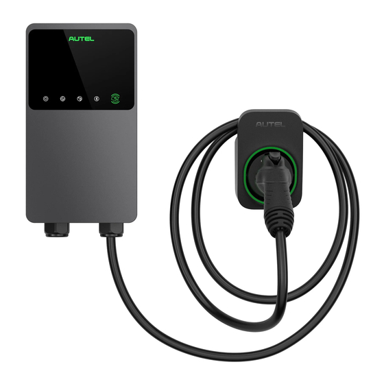
Product Overview
MaxiCharger AC Wallbox Home
1. LED Indicators (from left to right)
• Power LED
• Internet Connection LED
• Charging LED
• Bluetooth Connection LED
2. RFID LED
3. EV Charging Cable
4. Bottom AC Inlet Hole
Installation Guide
MaxiCharger AC Wallbox Home
• Do not use the equipment if the enclosure or the EV
connector is frayed, broken or otherwise damaged, or
fails to operate.
• Use 90 °C wire copper conductors only.
• Do not operate the equipment outside its operating tem-
perature range of -40 to 131 °F (-40 to 55 °C).
• Incorrect installation and testing of the equipment could
potentially damage the vehicle's battery, components,
and/or the equipment itself.
• Handle the equipment with care during transportation.
Do not subject it to strong force or impact or pull, twist,
tangle, drag or step on the equipment, to prevent
damage to it or any components.
1
(Separate Holster)
Maxi US AC W12-H
①
②
③
④
Advertisement

Related Manuals for Autel Maxi US AC W12-H


Summary of Contents for Autel Maxi US AC W12-H
- Page 1 Maxi US AC W12-H Thank you for purchasing this Autel MaxiCharger AC Wallbox Home. Our equipment is manufactured to a high standard and — when used according to these instructions and properly maintained — will provide years of trouble-free performance.
- Page 2 5. Bottom Ethernet Cable Port ⑤ 6. Mounting Screws 7. Rear AC Inlet Hole 8. Rear Ethernet Cable Port 9. Product Label ⑥ ⑨ ⑦ ⑧ 10. RJ45 Port 11. RS485 Port — connects the RS485 cables 12. Current Selector — adjusts the current for the charger...
-
Page 3: Led Indicators
LED Indicators Description • Solid Green: The charger is on. • Not Illuminated: The charger is off. • Flashing Yellow: Data transmission has started and/or firmware is upgrading. Power LED • Solid Yellow: Firmware upgrade has failed. • Solid Blue: Data transmission has failed; will illuminate in five seconds. •... - Page 4 IMPORTANT: A NEMA plug-in installation is only allowed with a 50 amp circuit. The MaxiCharger AC Wallbox Home can also be wired for higher amperages. Consult all applicable codes for breaker and wire sizing requirements. The field-wiring terminal is rated to 105 ˚C and accepts a maximum of 16 mm² (6 AWG) wire. Circuit Rating Max Load Estimated Range per Hour...
-
Page 5: Installing The Charger
Installing the Charger IMPORTANT: Switch off all electrical power prior to installation. NEMA Plug-in Installation To find the ideal mounting height of the charger: DANGER: Risk of shock. Turn off the power to the outlet at the circuit breaker until the installation is completed. 1. - Page 6 Attach the charger to the wall dock by inserting the mount- ing screws (D) on the back of the charger into the two upper mounting holes (C). Slide the charger downwards. Screw the M5 x 12 screw (E) into the hole at the bottom of the charger and tighten the screw to secure the charger using the screwdriver type T25.
- Page 7 Placement 1. Find the wall stud nearest to and on the right side of the power supply wiring using a wall stud finder. 2. Draw a vertical line of approximately 20" (50 cm) in line with the wall stud at the approximate height of your mounting. Place the wall dock with the center holes aligned with the vertical line.
- Page 8 Removing the NEMA Cable (Optional) In case you need to replace the NEMA cable with a Hardwire, remove the NEMA cable by unscrewing the terminal screws per the diagram. Then loosen the cable gland and pull down the NEMA cable. Power Supply Wiring IMPORTANT: •...
- Page 9 4. Remove the lower-left cable gland and install the bottom entry power conduit plug (G) to the charger. NOTE: The conduit fitting is not included. Bottom Entry: Insert the AC input cable into the inlet hole (H). L1 L2/N " 1.
- Page 10 Adjusting the Rated Current The MaxiCharger AC Wallbox Home allows you to manually set a lower maximum current using a current selector when installing your charger on a circuit rated lower than the maximum rating for your charger. 1. Remove the covers and locate the current selector. 2.
-
Page 11: Installing The Holster
Installing the Holster NOTE: Place the holster on a location where no tension is applied to the charging cable. 1. Place the wall dock on the wall and level it using a spirit level. 2. Mark the three mounting holes (I) with a pencil and drill three 5/16"... - Page 12 2. Scan the QR code below to download the Autel Charge app from the Google Play or App Store. 3. Open the Autel Charge app and select a desired function to start. FCC regulatory conformance: This device complies with Part 15 of the FCC Rules. Operation is subject to the following two conditions: (1) This device may not cause harmful interference.
- Page 13 IC regulatory conformance This device complies with CAN ICES-003 (B)/NMB-003(B). This device contains licence-exempt transmitter(s)/receiver(s) that comply with Innovation, Science and Economic Develop- ment Canada's licence-exempt RSS(s). Operation is subject to the following two conditions: (1) This device may not cause interference. (2) This device must accept any interference, including interference that may cause undesired operation of the device.
Need help?
Do you have a question about the Maxi US AC W12-H and is the answer not in the manual?
Questions and answers