
Related Manuals for Autel ATS100


Summary of Contents for Autel ATS100
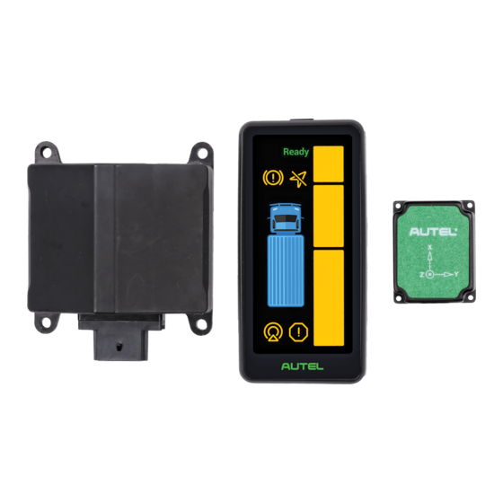
- Page 1 ATS100 (with GPS) Intelligent Turn Assistant User Guide Autel Intelligent Automobile Co., Ltd.
- Page 2 All other brands are trademarks or registered trademarks of their respective holders. Copyright Information No part of this manual may be reproduced without the prior written permission of Autel Intelligent Automobile Co., Ltd. reproduced, stored in a retrieval system, or transmitted in any form or by any means, electronic, mechanical, photocopied, recorded or otherwise.
-
Page 3: Table Of Contents
Table of contents ATS100 Turn Assistant Introduction ................4 ASR100 Radar Introduction ..................4 Warning display ......................6 GPS&IMU module ....................9 System connections and the cable harness .............. 9 User Manual ......................... 13 2.1 Radar installation ......................13 2.2 Radar wiring ........................17 2.3 Input signal for the system .................... -
Page 4: Ats100 Turn Assistant Introduction
The ATS100 turn assistant covers 180° on one side, no blind spots, with a target detec- tion range of up to 80 x 4.5m. With a compact structure, it has collision prediction and... - Page 5 Figure 1-2 ASR100 dimensions Performance parameters: working frequency 76-77GHz ±80 m (vehicle) Maximum detection range ±40 m (pedestrian/bicycle) working mode slow speed High speed minimum detection range 0.25m 0.9m distance resolution 0.31 m 0.96 m distance accuracy ±0.16m ±0.5m speed range ±60km/h ±150km/h speed accuracy...
-
Page 6: Warning Display
size 115mm x 95mm x 41mm weight 2 30g power consumption 6.5W communication interface CAN2.0, CAN_FD 8V - 32V; Passenger car 12V , operating voltage _ Commercial vehicle 24V -40℃ ~ 85℃ operating temperature _ storage temperature -40℃~105℃ installation angle redundancy -2°~2°... - Page 7 Figure 1-3 Display size The warning function is divided into three levels as follows:(Note: Conditions for activating the warning function: The vehicle speed is less than or equal to 30km/h.) Level 1 warning : The steering wheel angle is less than 30° and the object enters the warning area, then a section of warning light LEDs will light up, as shown in Figure 1-4.
- Page 8 Figure 1-4 Warning light description ① Warning module operation and status indicator: Lights up when the status of the warning module is normal. ② Brake Indicator: This light flashes when braking is active. (Currently this function is not available.) ③ GPS error indicator: lights up when the GPS sensor has no signal (temporarily), flashes when the GPS sensor has an permanent error signal.
-
Page 9: Gps&Imu Module
Troubleshooting: Table 1-1 Error description and troubleshooting Error Descrip- status symbol repair manual tion Warning mod- does not light up ule operation after switching Hardware failure and needs to be replaced and status dis- play possible reason: 1. Obstructed by objects such as snow, mud, etc. Radar Status The error lamp Indicator... - Page 10 Figure 1-5 System Connections Schematic Description of the radar wiring harness In the figure below, connector P1 is connected to the radar. It has 8 pins and the pin order is shown below. The pin number in the figure corresponds to the pin definition in Table 1-2.
- Page 11 CAN2.0_H -58~58VDC Green CAN2.0_L -58~58VDC Yellow CAN _FD _H -58~58VDC White CAN_FD_L -58~58VDC Violet GPS interface P2 definition table: Table 1-3 Definition of the GPS interface P2 Pin No. definition Area cable color CAN_FD_H -58~58VDC White CAN_FD_L -58~58VDC Violet VCC_SCREEN 8~32VDC GND_SCREEN 0 V DC voltage...
- Page 12 Figure 1-7 Display Wiring Harness Diagram GPS interface P4 definition table: Table 1-5 Definition of the GPS interface P4 Pin No. definition Area cable color CAN_FD_H -58~58VDC White CAN_FD_L -58~58VDC Violet 8~32VDC Dimensions 0 V DC voltage Black GPS_1 Rx 0 ~5VDC blue_ _ GPS_2 Tx...
-
Page 13: User Manual
2. User Guide 2.1 Radar installation Notes on installation The radar should be mounted on a low-vibration component. Strong vibrations will affect the detection function. The radar should be installed on the most protruding level on the side of the truck to prevent it from being blocked by other parts and affecting its detection perfor- mance. - Page 14 Mounting angle: the angle of rotation of the radar mounting position relative to the center of the rear axle of the vehicle; Warn_dx: the distance from the center of the rear axle to the front edge of the vehicle. Trailer length Figure 2-2 Diagram of calibration parameters for radar installation site The recommended or preconfigured sensor location is shown in Figure 2-3 below.
- Page 15 To parameterize the radar installation position, please use a Windows PC with the CAN box we have provided and our AutelRadarCfgTools software. First connect the CAN box with radar sensor via CAN 2.0 interface, see Table 1-2. The working steps are shown in Figure 2-4 below: (1) Click the Open button to open the CAN device (2) Click the Close button to close the CAN device...
- Page 16 Figure 2-4 AutelRadarCfgTools interface icon Maximum installation area: The maximum installation area is shown in Figure 2- 4.1. The sensor may be installed with software parameterization from the front of the vehicle up to a maximum of 700 cm to the rear. At the same time, the sensor must not be installed behind the first rear axle.
-
Page 17: Radar Wiring
To control installation variations, an optional additional mounting bracket can be used to adjust direction and angle during installation. 1. With the front of the radar (the side with the plastic case) facing the detection area, attach the radar to the mounting bracket with the screws. 2. -
Page 18: Input Signal For The System
GPS/IMU module is not used. Alternatively, the system can also be used if the input signals are provided via vehicle CAN Bus. The Autel ATS100 requires the 5 CAN signals shown below for its normal operation. By default, the radar automati- cally reads these CAN J1939 signals. -
Page 19: Power Access
identifier Tmax message type bytes or 0xCFE6CEE 50ms 50ms cyclic intel start signal _ byte length resolution offset minimum Maximum Unit vehicle speed 0.00390625 250,996 km/h identifier Tmax message type bytes or 0xCF0090B 20ms 20ms cyclic intel start lengt mini- signal _ byte resolution... -
Page 20: Installation Of Gps And Imu Module
2.5 Installation of GPS and IMU module The GPS/IMU module can be placed anywhere in the driver's cabin, the preferred po- sition is behind the windscreen and somewhere in the middle of the cockpit. a. Place the GPS&IMU module horizontally, noting that the X-axis direction is the same as the vehicle's forward direction. - Page 21 a. Remove the A-pillar cover and drill holes: Using the mounting holes on the bracket back plate as shown in Figure 1 as reference points, drill two 4.5mm mounting holes and one 12mm hole to pass the cable (30th hole). -40 mm below the mounting holes). b.
-
Page 22: Generation Of Installation Report
screws. e. Reinstall the cover on the A-pillar. 2 .7 Generation of installation report The AutelRadarCfgTools V2.3.60 has a function to print installation report or vehicle configuration report, which automatically creates a pdf file with the registered vehicle information, radar serial number and software version and radar installation location after user input the related information.
Need help?
Do you have a question about the ATS100 and is the answer not in the manual?
Questions and answers