Table of Contents
Advertisement
Quick Links
Advertisement
Table of Contents

Related Manuals for Autel MaxiCharger AC Elite


Summary of Contents for Autel MaxiCharger AC Elite
- Page 1 MaxiCharger AC Elite (Commercial) User Manual...
- Page 2 All information, specifications and illustrations in this manual are based on the latest information available at the time of printing. Autel reserves the right to make changes at any time without notice. While information of this manual has been carefully checked for accuracy, no guarantee is given for the completeness and correctness of the contents, including but not limited to the product specifications, functions, and illustrations.
-
Page 3: Safety Information
The safety messages herein cover situations Autel is aware of. Autel cannot know, evaluate or advise you as to all of the possible hazards. You must be certain that any condition or service procedure encountered does not jeopardize your personal safety. - Page 4 Do not use the equipment if the flexible power cord or EV cable is frayed, broken or otherwise damaged, or fails to operate. Do not use the equipment if the enclosure or the EV connector is frayed, broken or otherwise damaged, or fails to operate.
- Page 5 CAUTION To reduce the risk of electric shock, connect only to properly grounded outlets. ATTENTION Pour réduire le risque de choc électrique, brancher sur une prise correctement mise à la terre. CAUTION Risk of electric shock. Do not remove cover or attempt to open the enclosure. No user serviceable parts inside. Refer servicing to qualified service personnel.
-
Page 6: Table Of Contents
CONTENTS SAFETY INFORMATION ..........................II SAFETY MESSAGES ............................II USING THIS MANUAL ........................... 1 ..............................1 ONVENTIONS GENERAL INTRODUCTION ........................2 ............................2 RODUCT VERVIEW ................................. 5 N THE ............................6 ECOMMENDED OOLS INSTALLATION ............................7 .............................. 7 LECTRICAL ESIGN .......................... -
Page 7: Using This Manual
Using This Manual This manual describes the installation and use of the MaxiCharger AC Elite (commercial). Prior to installation, read through this manual to be familiarized with the instructions of this MaxiCharger to ensure a successful installation and smooth operations. -
Page 8: General Introduction
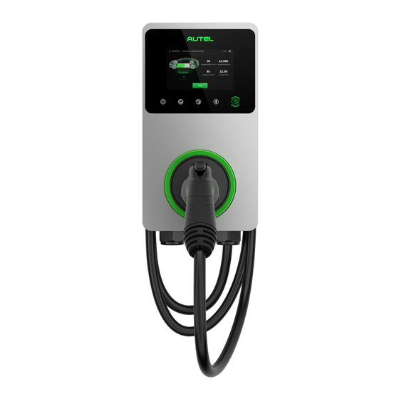
General Introduction The MaxiCharger AC Elite (commercial) is designed to charge a plug-in hybrid electric vehicle or an electric vehicle (hereinafter called EV) for commercial use. Our chargers provide you with safe, reliable, fast, and smart charging solutions. This manual will instruct you on how to install and use this charger. - Page 9 10. Mounting Screws 11. Rear AC Inlet Hole 12. Rear Ethernet Cable Port 13. Product Label 14. SIM Card Socket 15. RJ45 Port 16. RS485 Port — connects the RS485 cables 17. Current Selector — adjusts the current for the charger...
- Page 10 LED Description Description Solid Green: The charger is on. Not Illuminated: The charger is off. Flashing Yellow: Data is being transmitted and/or firmware is upgrading. Power LED Solid Yellow: Firmware upgrade has failed. Solid Blue: Data transmission has failed; will illuminate green in five seconds. ...
-
Page 11: In The Box
In the Box Ensure that all parts are delivered according to the order. Check the packages for the following parts. Charger Wall Dock 1 PC 1 PC Screw (M6 x 50) Screw (M5 x 12) 2 PCS 1 PC Bottom Entry Power Wall Anchor (5/16”) Conduit Plug (M32) 2 PCS... -
Page 12: Recommended Tools
2.3 Recommended Tools Wall stud finder Pencil or marker PH2 screwdriver 5/16” drill bit Power drill Spirit ruler Flathead screwdriver Multimeter NOTE The tools mentioned above are not included in the package. -
Page 13: Installation
Installation 3.1 Electrical Design 3.1.1 Upstream Wiring Chargers are considered continuous load devices (EVs draw maximum load for long durations); therefore, electrical branch circuits must be sized at 125% of the load for North American installations, in accordance with National Electric Code (NEC) requirements. (For other regions, refer to local code.) This means that for a maximum 40 A load at 208/240 V output to an electric vehicle, 50 A breaker is required. -
Page 14: Preparing For Installation
3.2 Preparing for Installation Install the charger on a flat and vertical surface capable of supporting its weight (e.g., a finished wall or pedestal). The maximum weight of a MaxiCharger AC Elite (commercial) is approximately 14.8 lbs. (6.7 kg). -
Page 15: Installing The Charger
The rear entry cables should be put through the cable inlet holes prior to mounting the charger to the wall dock. After the charger is installed, contact Autel support to complete the cloud setup for the charger to ensure its normal operation. - Page 16 STEP 2: Mounting the Wall Dock 1. Drill two 5/16" holes and insert two 5/16" diameter wall anchors into the lower mounting holes. 2. Attach the wall dock to the mounting location by inserting two M6 x 50 screws (B) into the lower mounting holes.
- Page 17 STEP 5: Removing the Covers 1. Remove the two screws (E) at the bottom of the charger with the T10 Torx screwdriver. Then remove the faceplate from the middle of the clasp (F). Set them aside. 2. Unscrew the eleven screws using the T10 Torx screwdriver.
-
Page 18: Power Supply Wiring
3.4 Power Supply Wiring IMPORTANT Use copper conductors with the maximum wire size of 6 AWG (16 mm²). Ensure that the screws for the terminal blocks are properly tightened. Ensure that there is no copper wire or debris left inside of the charger before switching on the electrical power to the charger. - Page 19 Bottom Entry Loosen the left cable gland and insert the AC input cable into the AC inlet hole. Step 2 1. Strip the wires to 1/2" (12 mm). 2. Connect the wires (L1, L2, and Ground) as per the diagram and tighten each connector screw to 17.7 in·lbs (2 N·m).
-
Page 20: Connecting The Ethernet Cable
3.5 Connecting the Ethernet Cable The charger can be connected to the Internet by Ethernet cable or SIM card. Via the Ethernet Cable: Step 1 Rear Entry 1. Pierce the rubber grommet and put the Ethernet cable (L) through it. 2. -
Page 21: Rs485 Cable Wiring (Optional)
Via the SIM card: 1. Use the T10 Torx screwdriver to loosen the security screw and open the SIM card cover. 2. Use a tool to press the tiny button next to the SIM card tray to eject the tray. 3. -
Page 22: Adjusting The Rated Current
3.7 Adjusting the Rated Current The MaxiCharger AC Elite (commercial) allows you to manually set a lower maximum current using a current selector when installing the charger on a circuit rated lower than the maximum rating for the charger. 1. Remove the covers and locate the current selector. -
Page 23: Troubleshooting
Troubleshooting Item Problems Solutions The charger is successfully Check whether the QR code on the charger is consistent with the QR added, but the Bluetooth code on the Quick Reference Guide. If so, make sure the Bluetooth is connection fails. enabled on your mobile device;... -
Page 24: Specifications
Specifications 5.1 Specifications Item Description Maximum 12 kW (240 VAC @ 50 A model) AC Power Output Rating 208/240 VAC, 60 Hz, single phase @ 16 A, 24 A, 32 A, 40 A, 48 A, 50 A AC Power Input Rating 20 A, 30 A, 40 A, 50 A, 60 A, 70 A (must be sized at 125% of the maximum load, e.g., 50 A breaker for Circuit Breaker Options (A) -
Page 25: Product Dimensions
Item Description 13.2” x 7.4” x 3.8” (336 x 187 x 97 mm) Dimension (H x W x D) 14.8 lbs. (6.7 kg) Weight NEC Article 625 and UL 916, UL 2594, UL2231-1, UL2231-2, UL 1998, CSA C22.1 Automatic reset feature is provided. Safety and Compliance AVERTISSEMENT Caractéristique de réarmement automatique incluse. -
Page 26: Compliance
Compliance FCC regulatory conformance: This device complies with Part 15 of the FCC Rules. Operation is subject to the following two conditions: (1) This device may not cause harmful interference. (2) This device must accept any interference received, including interference that may cause undesired operation. - Page 27 (2) Cet appareil doit accepter toute interférence, y compris les interférences susceptibles de provoquer un fonctionnement indésirable de l'appareil. RF Exposure This equipment complies with IC radiation exposure limits set forth for an uncontrolled environment. This equipment should be installed and operated with minimum distance of 20 cm between the radiator and your body.
- Page 28 www.autelenergy.com...
Need help?
Do you have a question about the MaxiCharger AC Elite and is the answer not in the manual?
Questions and answers