Table of Contents
Advertisement
Advertisement
Table of Contents

Related Manuals for Atlas Copco ZR 200


Summary of Contents for Atlas Copco ZR 200
- Page 1 AIF999999 ZR 200 Instruction book...
- Page 3 Atlas Copco ZR 200 AIF999999 Instruction book Original instructions COPYRIGHT NOTICE Any unauthorized use or copying of the contents or any part thereof is prohibited. This applies in particular to trademarks, model denominations, part numbers and drawings. This instruction book is valid for CE as well as non-CE labelled machines. It meets the requirements for instructions specified by the applicable European directives as identified in the Declaration of Conformity.
-
Page 4: Table Of Contents
Instruction book Table of contents Safety precautions......................5 ........................... 5 AFETY ICONS ......................5 ENERAL SAFETY PRECAUTIONS ................... 6 AFETY PRECAUTIONS DURING INSTALLATION ....................7 AFETY PRECAUTIONS DURING OPERATION ................8 AFETY PRECAUTIONS DURING MAINTENANCE OR REPAIR .......................10 ISMANTLING AND DISPOSAL General description...................... 11 ..........................11 NTRODUCTION ............................ - Page 5 Instruction book 3.11 ........................41 ACHINE SETTINGS MENU 3.12 ......................44 ONTROLLER SETTINGS MENU 3.13 ..........................47 CCESS LEVEL Installation........................49 ........................49 IMENSION DRAWING ........................51 NSTALLATION PROPOSAL ..............53 NSTALLATION REQUIREMENTS FOR RUBBER COMPENSATORS .................. 60 LECTRIC CABLE SIZE FUSES AND CABLE LENGTH ........................
- Page 6 Instruction book Servicing procedures....................93 ............................ 93 IR FILTERS .......................94 IL AND OIL FILTER CHANGE ..........................95 AFETY VALVES ............................95 OOLERS Problem solving......................97 ........................... 97 ROBLEM SOLVING Technical data.......................99 ............................99 EADINGS ......................99 ETTINGS OF SAFETY VALVES ......................99 ETTINGS FOR OVERLOAD RELAY .........................
-
Page 7: Safety Precautions
Instruction book Safety precautions Safety icons Explanation Danger to life Warning Important note General safety precautions 1. The operator must employ safe working practices and observe all related work safety requirements and regulations. 2. If any of the following statements does not comply with the applicable legislation, the stricter of the two shall apply. -
Page 8: Safety Precautions During Installation
Instruction book 9. If compressed air is used in the food industry and more specifically for direct food contact, it is recommended, for optimal safety, to use certified Class 0 compressors in combination with appropriate filtration depending on the application. Please contact your customer center for advice on specific filtration. -
Page 9: Safety Precautions During Operation
Instruction book 12. The electrical connections must correspond to the applicable codes. The machines must be earthed and protected against short circuits by fuses in all phases. A lockable power isolating switch must be installed near the compressor. 13. On machines with automatic start/stop system or if the automatic restart function after voltage failure is activated, a sign stating "This machine may start without warning"... -
Page 10: Safety Precautions During Maintenance Or Repair
Instruction book 6. Keep all bodywork doors shut during operation. The doors may be opened for short periods only, e.g. to carry out routine checks. Wear ear protectors when opening a door. On machines without bodywork, wear ear protection in the vicinity of the machine. 7. - Page 11 Instruction book 3. Use only genuine spare parts for maintenance or repair. The manufacturer will disclaim all damage or injuries caused by the use of non-genuine spare parts. 4. All maintenance work shall only be undertaken when the machine has cooled down. 5.
-
Page 12: Dismantling And Disposal
Instruction book Also consult following safety precautions: Safety precautions during installation Safety precautions during operation. These precautions apply to machinery processing or consuming air or inert gas. Processing of any other gas requires additional safety precautions typical to the application which are not included herein. Some precautions are general and cover several machine types and equipment;... -
Page 13: General Description
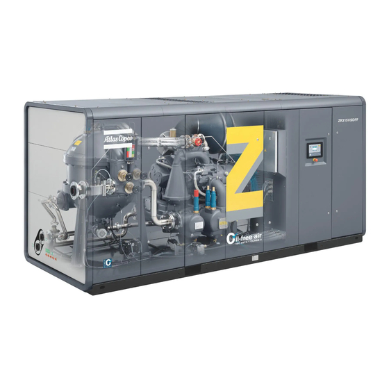
Instruction book General description Introduction General views General view of ZR 160 up to ZR 275 FF Ref. Name Compressed air outlet Condensate drain receiver, aftercooler Condensate drain receiver, intercooler Elektronikon Mk5–Touch regulator Safety valve, high pressure Safety valve, low pressure Emergency stop button Cooling water inlet Cooling water outlet... - Page 14 Instruction book • Air filter • Low-pressure compressor element • Intercooler • High-pressure compressor element • Aftercooler • Water separators • Electric motor • Drive coupling • Gear casing • Elektronikon control system • Safety valves Drive arrangement On ARR E, the motor is flanged to the gear casing by means of a coupling housing. The motor/ gear casing unit is supported on the frame by vibration dampers.
-
Page 15: Air System
Instruction book Air system Flow diagram Flow diagram of ZR 110 up to ZR 275 and ZR 132 VSD up to ZR 315 VSD compressors Reference Name Air filter Air outlet AIF999999... - Page 16 Instruction book Reference Name Silencer By-pass valve Aftercooler Intercooler Oil cooler Check valve High-pressure compressor element Low-pressure compressor element Moisture trap, aftercooler Moisture trap, intercooler Oil filter Oil pump Description Air drawn through the filter (AF) is compressed in the low-pressure compressor element (El). On ZR compressors, the compressed air is discharged to the intercooler (Ci).
-
Page 17: Cooling And Condensate Drain System
Instruction book Cooling and condensate drain system Flow diagram Flow diagram of ZR 110 up to ZR 275 compressors Reference Name Air filter Air outlet AIF999999... -
Page 18: Elektronikon Regulated Drain (Erd)
Instruction book Reference Name Silencer By-pass valve Aftercooler Intercooler Oil cooler Check valve High-pressure compressor element Low-pressure compressor element Moisture trap, aftercooler Moisture trap, intercooler Oil filter Oil pump Cooling system for ZR compressors The cooling water flows through oil cooler (Co), the cooling jackets of high-pressure compressor element (Eh) and low-pressure compressor element (El), as well as through intercooler (Ci) and aftercooler (Ca). - Page 19 Instruction book Reference Description Solenoid valve Connector Sensor Bushing Drain receiver If the controller detects water in the intercooler or aftercooler drain receiver for too long a period, a shutdown is generated. If water is detected on the integrated dryer drain receiver for too long a period, a warning is generated.
-
Page 20: Oil System
Instruction book Oil system Flow diagram Flow diagram of ZR 110 up to ZR 275 compressors and ZR 132 VSD up to ZR 315 VSD compressors Reference Name Air filter Air outlet AIF999999... -
Page 21: Regulating System
Instruction book Reference Name Silencer By-pass valve Aftercooler Intercooler Oil cooler Check valve High-pressure compressor element Low-pressure compressor element Moisture trap, aftercooler Moisture trap, intercooler Oil filter Oil pump Description Oil is circulated by pump (OP) from the sump of the gear casing through cooler (Co). The oil passes through oil filter (OF) towards the bearings and timing gears. - Page 22 Instruction book During unloading If the air consumption is less than the air delivery of the compressor, the net pressure increases. When the net pressure reaches the upper limit of the working pressure (unloading pressure), solenoid valve (Y1) is de-energised. The plunger of solenoid valve (Y1) moves by spring force shutting off the control air supply to unloader (UA).
-
Page 23: Connectivity And Smartlink
Instruction book During loading When the net pressure decreases to the lower limit of the working pressure (loading pressure), solenoid valve (Y1) is energised. The plunger of solenoid valve (Y1) moves against the spring force opening the control air supply port to unloader (UA). Phase Description Atmospheric pressure is allowed through solenoid valve (Y1) to chamber (1) of unloader... - Page 24 SMARTLINK Service rules out all uncertainties. Scheduling maintenance visits becomes as simple and easy as it should be; the service log book is always just one click away and the online link with Atlas Copco allows to request and quickly receive quotes for spare parts or additional services.
- Page 25 Instruction book • Use the data of the SMARTLINK–ready machine to register as a user. • You will receive an e-mail with login credentials. • Go to the SMARTLINK web site http://www.atlascopco.com/smartlink, log in with the user credentials. • Enjoy SMARTLINK! •...
-
Page 26: Elektronikon™ Touch Controller
Instruction book Elektronikon™ Touch controller Controller The Elektronikon™ Touch controller Introduction The controller has the following functions: • Controlling the unit • Protecting the unit • Monitoring components subject to service • Automatic restart after voltage failure (ARAVF) Automatic control of the unit The controller maintains the net pressure between programmable limits by automatically loading and unloading the unit (fixed speed units) or by adapting the motor speed (units with frequency converter). - Page 27 Instruction book Protecting the unit Shutdown Several sensors are provided on the unit. If one of the measured signals exceeds the programmed shutdown level, the unit will be stopped. Example: If the element outlet temperature exceeds the programmed shutdown level, the unit will be stopped.
-
Page 28: Control Panel
Instruction book Control panel Control panel Parts and functions Reference Designation Function Touch screen Shows the unit operating condition and several icons to navigate through the menu. The screen can be operated by touch. Warning sign Flashes in case of a shut-down and is lit in case of a warning condition. -
Page 29: Icons Used
Instruction book Icons used Menu icons Menu Icon Menu Icon Menu Icon Data Status Inputs Outputs Counters Aux. Equipment Converters Parameters Service Service Overview Service Plan Service History Service functions Clean Screen Week Timer Week Remaining Running Time Event History Saved Data AIF999999... - Page 30 Instruction book Menu Icon Menu Icon Menu Icon Machine Alarms Settings Regulation Control Parameters Aux. Equipment Converter(s) Parameters Internal SmartBox Auto Restart Controller Network Ethernet Settings Settings Settings CAN Settings Localisation Language Date/Time Units User Password Help Information Status icons Icon Description Motor Stopped...
- Page 31 Instruction book Motor Stopped Wait Running Unloaded Manual Unload Running Unloaded Wait Running Loaded Failed to Load Running Loaded Wait Manual Stop Machine Control Mode, Local Machine Control Mode, Remote Machine Control Mode, LAN Automatic Restart After Voltage Failure Week Timer Active System icons Icon Description...
- Page 32 Instruction book Antenna 50% Antenna 75% Antenna 100% Change between screens (indication) Energy recovery Dryer Element Drain(s) Analogue Output Menu Reset Auto Restart Filter(s) Cooler Valve(s) Power Meter Input icons Icon Description Pressure AIF999999...
-
Page 33: Main Screen
Instruction book Temperature Special Protection Open Closed This chapter gives a general survey of available icons. Not all icons mentioned in this chapter are applicable to every machine. Main screen Function The Main screen is the screen that is shown automatically when the voltage is switched on. It is switched off automatically after a few minutes when there is no touch input. -
Page 34: Quick Access Screen
Instruction book Reference Designation Function Alarm button The alarm button can be tapped to show the current alarms. If an alarm occurs, the icon on the button will be red. Service button The service button can be tapped to show the service information. -
Page 35: Menu Screen
Instruction book Function Description Setpoints Several setpoints can be modified by tapping this icon. Control mode The control mode can be changed by tapping this icon. • Local control via start/stop buttons • Remote control via digital input(s) • LAN control via the network. When in Remote or LAN control, the start/stop buttons on the controller will not work. - Page 36 Instruction book Reference Designation Function Service The service menu contains the Service information. The ‘Clean screen’ function can be used to clean the touchscreen. Week timer Multiple Week timers and a Remaining running time can be set through this menu. Event history In case of an alarm, the Status information of the unit is saved and can be viewed through this menu.
-
Page 37: Data Menu
Instruction book Data menu Function This screen is used to display the following submenus: • Status • Inputs • Outputs • Counters • Aux. Equipment These submenus can be entered by tapping the icons. Procedure To enter the Data menu screen: 1. - Page 38 Instruction book If an alarm is active, it can be viewed by tapping the alarm message. To reset an alarm, tap the reset button (1). Before remedying, consult the Safety precautions. Before resetting a warning or shutdown message, always solve the problem. Frequently resetting these messages without remedying may damage the unit.
-
Page 39: Service Menu
Instruction book This menu shows an overview of all actual hours and counters of the unit and controller. Auxiliary equipment menu Tap the Aux. Equipment icon to enter the Aux. equipment menu. This menu shows an overview of all auxiliary equipment fitted. Service menu Function This screen is used to display the following submenus:... - Page 40 Instruction book Description Reference Designation Service Service functions (Only visible as advanced user) Clean screen Service menu Tap the Service icon to enter the Service menu. This menu shows the remaining Running Hours and the remaining Real Time Hours until the next service.
-
Page 41: Week Timer Menu
Instruction book Depending on the machine, this menu can have a different set of functions. Many of them are password protected, as they are only accessible for authorized personnel. Clean screen Tap the Clean Screen icon to start the 15 seconds countdown to perform cleaning of the touchscreen. -
Page 42: 3.10 Event History Menu
Instruction book Description Reference Designation Function Add or select week If less than 4 weeks are programmed, tap the ‘+’ button to add a week. Remove week Tap to remove a programmed week timer. Activate week timer A selection screen pops up. The user can choose the correct week by tapping ‘–’... -
Page 43: 3.11 Machine Settings Menu
Instruction book Reference Designation Saved Data Saved data Tap the Saved Data icon to enter the Saved Data menu. Scroll through the items swiping up and down in this list. The event date and time is shown at the right side of the screen. Press on one of the items in the list for more information reflecting the status of the unit when the shutdown occurred. - Page 44 Instruction book Description Reference Designation Alarms menu Regulation menu Control Parameters menu Aux. Equipment Parameters menu Auto Restart menu Alarms menu Tap the Alarms icon to enter the Alarms menu. A list of all alarms is shown. When pressing on one of the items in this list, the warning and/or shutdown levels are shown for this alarm.
- Page 45 Instruction book When tapping a list item, a selection screen pops up. The user can modify the setting by tapping ‘–’ or ‘+’ and can confirm by tapping ‘V’ or decline by tapping ‘X’. Change a selection When tapping a list item, a selection screen pops up. The user can change the selection by swiping up or down and confirm by tapping ‘V’...
-
Page 46: 3.12 Controller Settings Menu
Instruction book Through this menu, the automatic restart can be activated. The activation is password protected. The automatic restart settings can also be changed. Enter a password When tapping a password protected item, a selection screen pops up. The user can enter the password by swiping up or down to select the desired number. - Page 47 Instruction book Reference Designation Network Settings menu Localisation menu User Password menu Help menu Information menu Network settings menu Tap the Network Settings icon to enter the Network Settings menu. Ethernet Settings The list of Ethernet Settings is shown. When ethernet is turned off, the settings can be modified. CAN Settings The list of CAN Settings is shown.
- Page 48 Instruction book The date and time settings of the controller can be modified through this menu. Units The units displayed can be modified through this menu. Modify a setting When tapping a list item, a selection screen pops up. The user can modify the setting by tapping ‘–’...
-
Page 49: 3.13 Access Level
Instruction book This menu shows information about the controller. 3.13 Access level Function Through this pop-up screen the access level settings can be viewed or changed. Procedure The Access Level screen can be viewed or changed by tapping the Access Level button at the upper right corner of the screen. - Page 50 Instruction book Service access level Tap the Service access level icon (1) and confirm (2). The screen information bar (1) now shows the current status of the unit instead of the machine serial number. The Received Signal Strength Indicator (RSSI) value is now shown in the Internal SmartBox menu.
-
Page 51: Installation
Instruction book Installation Dimension drawing Dimensions Dimension drawing of ZR 160 up to ZR 275 Pack and ZR 250/315 VSD Pack compressors (in imperial units) AIF999999... - Page 52 Instruction book Reference Description Right side view Front view Motor cooling air outlet Compressed air inlet Motor cooling air inlet (only for option: separate air intake) Motor cooling air inlet + compressor air inlet (for standard unit) Automatic drain of intercooler G 1/2" (female) Automatic drain of aftercooler G 1/2"...
-
Page 53: Installation Proposal
Instruction book Installation proposal Compressor room example Installation proposal for ZR 160 Pack up to ZR 275 Pack (in inch) Minimum free area to be reserved. Ventilation proposal. AIF999999... - Page 54 Instruction book Rear side view. Ventilation proposal (without option separate air intake). Ventilation proposal (with option separate air intake). Common ducting for multiple units is not allowed. Reverse side view. Description The compressor must only be moved or lifted as described in the section Initial start-up.
-
Page 55: Installation Requirements For Rubber Compensators
Installation requirements for rubber compensators Types and sizes Atlas Copco oil-free air products with aftercooler are equipped with rubber compensators on the air outlet and water connections. Types of misalignments The supplied compensators can cope with 2 types of minor misalignments when the customer... - Page 56 Instruction book • Axial ΔL • Lateral ΔR Drawing reference Description Atlas Copco compressor pipe end Customer installation pipe end Angular misalignments Δα are NOT allowed! AIF999999...
- Page 57 Instruction book Misalignment tolerances • Single direction misalignments Axial : ΔL Lateral: ΔR Δα ° = stretch or compression = NO angular misalignment is tolerated! • Combined direction misalignments Drawing reference Description Compression Stretch Do NOT operate outside of the black polygon. Do NOT exceed the misalignment tolerances to avoid compensator damage! The piping system of the customer should be designed to fit the misalignment tolerances both during standstill and operation.
- Page 58 Instruction book Medium temperature Correction factor for maximum working pressure of (°F) the compensator 0.92 0.83 0.75 0.67 0.54 Torque values Compensator bolts should be torqued in 3 successive steps • Step 1: Hand-tighten each bolt. • Step 2: Torque the bolts crosswise up to the value mentioned in the table below and allow a stabilization period of 30 minutes before moving to step 3.
- Page 59 Instruction book The compensator loads (F and F ) that are mentioned on the drawing are strictly forbidden: • Weight loads F • Thrust forces F For the design of piping and supporting structures, use an approved standard code (e.g. EN 13480 or ASME 16.5/B31.3).
- Page 60 Instruction book Situation Description Flat DIN flanges prevent damage of the rubber sealings. Collared flanges prevent premature wear. Add a flat sealing or if necessary a metal disc with flat seal in case of damage risk. Avoid excessive torque to prevent damage to the bended pipes or the sealings. Rubber sealings will get damaged when the inner pipe diameter exceeds the inner sealing diameter.
- Page 61 Instruction book • CORRECT installation! AIF999999...
-
Page 62: Electric Cable Size, Fuses And Cable Length
Instruction book Drawing reference Description Larger than maximum allowed installation length. Less than or equal to maximum allowed installation length Minimum 1 mm of free space Do NOT: • Paint the rubber bellows of the expansion joint since: • Solvents can damage the rubber cover. •... -
Page 63: Electric Connection
2 x(3 X 65 kA 200) ZT/ZR 160 2 X (3 X0000+2AWG) 2 x(3 X 65 kA 225) ZT/ZR 200 2 X (3 X 300MCM 2 x(3 X 65 kA +2AWG) 300) ZT/ZR 250 4 X (3 X 00+4AWG) 2 x(3 X... - Page 64 Instruction book Electric connections Electric connections for compressors with star-delta starter (Model year 2003) AIF999999...
- Page 65 Instruction book Electric connections for compressors with star-delta starter (Model year 2014) AIF999999...
- Page 66 Instruction book Electric connections Electric connections for compressors with star-delta starter (Model year 2019) Text on figures Reference Text on figure Customer’s installation K21, K23 larger than or equal to 56 with 6 type “2” fuses K21, K23 larger than or equal to 56 with 3 type “1” fuses K21, K23 smaller than 56 with 3 type “2”...
-
Page 67: Quality Of Safety Components
Instruction book Reference Text on figure (17) Customer's motor starter (18) Separate low voltage supply or transformer (19) For compressors with motor supply voltage > 690 V (20) 6 Fuses Quality of safety components When installing a remote emergency button or a motor contactor, the following B10d values are advised: •... - Page 68 • Energy Recovery (water temperature up to 95°C / 203°F) Water quality A full instruction for handling cooling water data is available at Atlas Copco. In case water is not in line with recommended values or if any doubt, please refer to Atlas Copco. Technical specifications Parameter...
- Page 69 Instruction book Parameter Unit Single Pass Single Pass Recirculating Closed Closed (65°C / (95°C / (65°C / 149°F) System System 149°F) 203°F) (65°C / (95°C / 149°F) 203°F) Total Alkalinity No limits indicated. To be measured for calculating RSI. CaCO Ryznar Stability 5.6 - 7.5 N.A.
- Page 70 Instruction book Ryznar Stability Index (RSI) The Ryznar Stability Index (RSI) is a parameter for predicting whether water will tend to dissolve or precipitate calcium carbonate. The adhesion of scaling deposits and their effect are different on different materials, but the equilibrium of the water (scaling or corrosive) is only determined by its actual pH value and by the saturation pH value (pH The saturation pH value is determined by the relationship between the calcium hardness, the total alkalinity, the total solids concentration and the temperature.
- Page 71 Instruction book Chloride Water condition Maximum 65°C / Maximum 95°C / 203 limit 149°F °F 6.9<RSI<7.5 350 ppm Slight corrosion Water treatment not Water treatment not necessary. necessary. Occasional inspection Occasional inspection recommended. recommended. 7.6<RSI<9.0 200 ppm Strong corrosion Regular control Regular control necessary.
-
Page 72: General Pictographs
Instruction book Closed loop system Chloride Water condition Maximum 65°C / 149°F and limit 95°C / 203°F RSI<3.9 200 ppm Very high scale formation Water cannot be used. 4.0<RSI<5.5 200 ppm High scale formation Treat water to reduce scaling character 5.6<RSI<6.2 350 ppm Slight scale formation... - Page 73 Instruction book Reference Name Before connecting the compressor electrically, consult the Instruction manual for the motor rotation direction Torques for steel (Fe) or brass (CuZn) bolts Consult the Instruction manual before greasing Switch off the voltage before removing the protecting cover inside the electric cabinet Oil the gaskets, screw on the filters and tighten by hand (approx.
-
Page 74: Operating Instructions
Instruction book Operating instructions Initial start-up Safety precautions The operator must apply all relevant Safety precautions. Ambient conditions / altitude opeartion Refer to Limitations for the limits of ambient conditions and altitude operation. If the compressor is operated beyond these limits, precautions must be taken. If this is the case, consult your Atlas Copco Customer Center. - Page 75 Instruction book Transport fixtures on the motor side in ZR/ZT 110 up to ZR/ZT 275 On the motor side, the dampers are secured by means of bolts/spacers. Remove the bolts and spacers (1 and 2). Transport fixtures on the gear casing side in ZR/ZT 110 up to ZR/ZT 275 On ZR/ZT 110 up to ZR/ZT 275, a transport support (1) is fitted to the gear casing.
- Page 76 Instruction book Silica gel bags Position of silica gel bags on ZR 160 up to ZR 275 Remove flange (1) and take out the silica gel bags. Refit the flange. Water circuit of ZR compressors Water drain plug, HP element of ZR 110 up to 275 AIF999999...
- Page 77 Instruction book Water drain plug, LP element of ZR 110 up to 275 Water drain plugs, coolers of ZR 110 up to 275 Water drain plug, cooler block of ZR 110 up to 275 AIF999999...
- Page 78 Instruction book Water drain plug, oil cooler of ZR 110 up to 275 Step Action Fit the water drain plugs (DP2 up to DP6) that are attached to the water pipe of one of the compressor elements (El and Eh) in a plastic bag. The plugs are painted green and their positions are shown on the illustrations above.
- Page 79 Instruction book Oil circuit Position of oil level sight-glass on ZR 110 up to ZR 275 Check that oil is visible in sight-glass (SG). AIF999999...
- Page 80 Instruction book Start-up Electric cabinet of compressor with starter 1. Check that the voltage selecting wires on transformer T1 are connected correctly. An instruction label is provided. 2. Check that the electrical installation meets local regulations. 3. On compressors with a starter, check the overload relay setting (F21) and check that the relay is set for automatic resetting.
-
Page 81: Before Starting
Instruction book Before starting The operator must apply all relevant Safety precautions. If the water system has been drained, close the drain valves and fit the drain plugs or pipe. Oil level Oil system components, ZR 110 up to ZR 275 On ZR/ZT 110 up to ZR/ZT 275, the oil level must be in the middle of the sight-glass (SG) after stopping (in the case of longer standstill, the oil level may increase in the sight-glass). - Page 82 Instruction book Condensate drains Drain connections on ZR 160 Pack up to ZR 275 Pack Reference Description Compressed air outlet Automatic drain, aftercooler Daea Automatic drain, extra aftercooler (for Energy Recovery option only) Automatic drain, intercooler Water inlet Water outlet Open the water inlet valve and outlet valve (customer's installation).
-
Page 83: Routine Starting
Instruction book Routine starting Control panel Control panel of Elektronikon controller AIF999999... - Page 84 Instruction book Procedure Step Action Open the air outlet valve (customer's installation). Switch on the voltage and check that voltage on sign (5) lights up. Press start button (7). The compressor starts running in unloaded condition and operation sign (4) lights up. Approx.
-
Page 85: Starting After Emergency Stop Or Shutdown
Instruction book Starting after emergency stop or shutdown Control panel Control panel of controller Procedure Step Action Press the emergency stop button (if not yet done). Switch off the voltage and then depressurize the compressor. Remedy the fault. Unlock the emergency stop button by pulling it back. Reset the protection warning in the Elektronikon controller. -
Page 86: During Operation
Instruction book Manual restart In automatic operation, the regulator limits the number of motor starts. During operation Control panel Control panel of Elektronikon controller Procedure When operation sign (4) is alight, starting and stopping of the motor is automatically controlled: when the motor is stopped, it may restart automatically. Step Action Check the readings on the touchscreen (1). -
Page 87: Checking The Display
Instruction book Checking the display Control panel Control panel of controller Procedure 1. Regularly check the display for readings and messages. Normally, the main display is shown. 2. Always check the display and remedy the trouble if warning sign (2) is alight or blinks. The display will show a service message if a service plan interval has been exceeded or if a service level for a monitored component has been exceeded. -
Page 88: Manual Loading/Unloading
Instruction book Manual loading/unloading Control panel Control panel of controller General Normally, the compressor runs in automatic operation, i.e. the electronic regulator loads, unloads, stops and restarts the compressor automatically. Sign (4) is then alight. If required, the compressor can be unloaded manually. In this case, the compressor is switched out of automatic operation i.e. -
Page 89: Stopping
Instruction book Stopping Control panel Control panel of Elektronikon controller Procedure The operator must apply all relevant safety precautions. Frequently stopping the compressor using the emergency stop button may damage the compressor. Only use the emergency stop button in case of emergency. Step Action Press stop button (6). -
Page 90: Taking Out Of Operation
Instruction book Taking out of operation Procedure At the end of the service life of the compressor, proceed as follows: Step Action Close the air outlet valve and stop the compressor. On compressors with an Elektronikon regulator, press the emergency stop button. Switch off the voltage and disconnect the compressor from the mains. -
Page 91: Maintenance
Warranty-Product Liability Use only authorized parts at the correct intervals (check with your local Atlas Copco Service center). Any damage or malfunction caused by the use of unauthorized parts or unqualified personnel is not covered by Warranty or Product Liability. In the event of any extended warranty,... - Page 92 Atlas Copco filters to guarantee the performance of your compressor. • Grease the motor bearings at the correct interval and with the correct grease type and quantity as mentioned on the motor data plate. If in doubt, consult your Atlas Copco Service center.
-
Page 93: Motor Greasing
Instruction book Activities Level A Level B Level C Check critical bolt/coupling connections Check operation of safety valves Check for presence of water in lube oil Change Roto Z oil (16000 hrs or 2-yearly) Inspect/change air filter element(s) Check condition of air intake chamber Change compressor oil filter (4000 hrs or annually) Replace filter element of gear case breather Check cycle of air intake throttle valve... -
Page 94: Oil Specifications
The bearings of the fan motor are greased for life. Oil specifications Roto-Z lubricating oil Use Atlas Copco Roto-Z oil which is specially developed for oil-free rotary compressors. This oil has a long service life and ensures optimum lubrication. Atlas Copco Roto-Z oil can be ordered in following quantities:... -
Page 95: Servicing Procedures
Instruction book Servicing procedures Air filters Location of the air filters Air filter of ZR/ZT 110 up to ZR/ZT 275 Procedure The filters must be serviced regularly; consult section Preventive maintenance schedule. Never install damaged or clogged filters. Procedure for ZR/ZT 110 up to ZR/ZT 275 and ZR/ZT 132 VSD up to ZR/ZT 315 VSD Step Action Stop the compressor and press the emergency stop button. -
Page 96: Oil And Oil Filter Change
Instruction book Oil and oil filter change Oil system Oil system components, ZR 110 up to ZR 275 Procedure Step Action Run the compressor until warm. Stop the compressor. Press the emergency stop button. Switch off the voltage and follow the LOTO procedure. (Refer to the Safety Precautions before acting.) The filler plug and drain points are painted yellow. -
Page 97: Safety Valves
The valves can be tested on a separate compressed air line. If a valve does not open at the pressure specified in Settings of safety valves, consult Atlas Copco. Never run the compressor without safety valves. No adjustments are allowed. - Page 98 Instruction book Coolers of water-cooled Full-Feature compressors Drawing reference Description Aftercooler AC (ER) Extra aftercooler in case of the energy recovery option Intercooler Oil cooler Regeneration cooler (only on Full-Feature compressors) Keep the coolers clean to ensure cooling efficiency. AIF999999...
-
Page 99: Problem Solving
Instruction book Problem solving Problem solving • Before starting any maintenance or repairs, stop the compressor. • Depressurize the air system as follows: • Close the air outlet valve. • On compressors equipped with Electronic Water Drains (EWD), press the test buttons on top of the electronic water drains. - Page 100 Check water temperature and increase insufficient cooling water flow cooling water flow On ZR compressors, restriction in cooling water Consult the Atlas Copco Customer Center system due to formation of scale or dirt deposits Unloading pressure incorrectly Check the controller setting.
-
Page 101: Technical Data
The readings below are indicative values when operating at reference conditions. Check the section Reference conditions. These values are no rejection limits. In case of doubt, consult your Atlas Copco Customer Center. For the maximum working pressure and the outlet pressure, consult the section Compressor data. Pressure readings... -
Page 102: Reference Conditions
Instruction book Supply voltage Recommended overload setting F21 ZR/ZT 200 compressors designed for a maximum inlet temperature of 40 ˚C/104 ˚F with IE3 motor Supply voltage Recommended overload setting F21 Reference conditions Absolute inlet pressure 14.5 psi(a) Ambient temperature 68 °F Air inlet temperature 68 °F Effective working pressure... -
Page 103: Compressor Data
Approx. 77 ˚F Inlet of cooling water Below 104 ˚F Outlet of cooling water Below 122 ˚F Oil quantity in the lubrication system of the compressor Compressor type US gal ZR 160, ZR 200, ZR 250, ZR 275 15.85 AIF999999... -
Page 104: Pressure Equipment Directives
Instruction book Pressure equipment directives ZR 160 Pack up to ZR 275 Pack compressors are a pressure assembly of cat. II according to 2014/68/EU. Parts of article 4.3 of 2014/68/EU are subject to Sound Engineering Practice (SEP). Parts of category I according to 2014/68/EU are integrated into the machine and fall under the exclusion of article 1.2, (f)(i). - Page 105 Instruction book Reference Name Intercooler Aftercooler Position of data plate Heat exchanger ZR 160-275 PED Category CAT II Design code ASME BPVC Section VIII, div 1 Material SA-395 Bolts Interval of periodic 5 years or the frequency as given in national legislation inspection by 3rd party (1) Intercooler...
-
Page 106: Documentation
Instruction book Documentation Declaration of conformity Typical example of a Declaration of Conformity document (1): Manufacturer (2): Applicable directives (3): Standards used (4): Technical file holder AIF999999... - Page 107 Instruction book (5): Contact address of the manufacturer On the Declaration of Conformity, the harmonized and/or other standards that have been used for the design are shown and/or referred to. The Declaration of Conformity is part of the documentation that is supplied with this device. AIF999999...
- Page 110 This is what we call - Sustainable Productivity. Atlas Copco Airpower Oil-free Air Division, Boomsesteenweg 957, 2610 Wilrijk, Belgium Phone: +32 (0)3 870 21 11 Atlas Copco Airpower NV. All rights reserved. Designs and specifications are subject to change without notice or obligation.
Need help?
Do you have a question about the ZR 200 and is the answer not in the manual?
Questions and answers