
Related Manuals for Atlas Copco XAS 400 JD IT4 HOP


Summary of Contents for Atlas Copco XAS 400 JD IT4 HOP
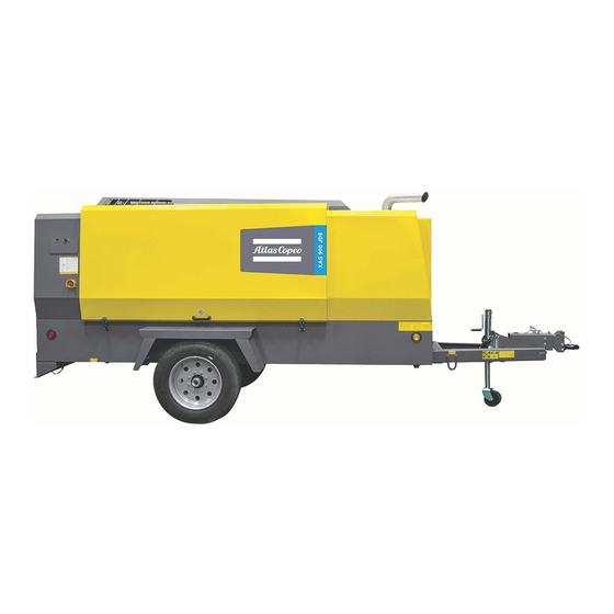
- Page 1 Instruction Manual for AC Compressors English Engine JD4045HFC92 XAS 400 JD IT4 HOP XATS 400 JD IT4 HOP Engine JD4045HFC93 XAVS 400 JD IT4 HOP...
- Page 3 Instruction Manual for AC Compressor XAS 400 JD IT4 HOP XATS 400 JD IT4 HOP XAVS 400 JD IT4 HOP Original instructions Printed matter Nr 1310 3129 33 ATLAS COPCO - PORTABLE ENERGY DIVISION 11/2012 www.atlascopco.com...
- Page 4 Neglecting maintenance or making changes to the setup of the machine can result in major hazards, including fire risk. While every effort has been made to ensure that the information in this manual is correct, Atlas Copco does not assume responsibility for possible errors.
-
Page 5: Table Of Contents
Preface Table of contents 5.3.8 Power ON / OFF ..........5.3.9 Starting .............. Please read the following instructions carefully before 5.3.10 Warming up............starting to use your compressor. Safety precautions........7 5.3.11 Loading ............. 1.1 Introduction ............7 It is a solid, safe and reliable machine, built according to 5.3.12 Stopping ............ - Page 6 6.15 Compressor element overhaul ......52 11.1 General ............. 69 11.2 Disposal of materials ........70 Adjustments and servicing procedures . 53 Maintenance Log ........71 7.1 Adjustment of the continuous pneumatic regulating system ......53 7.2 Air filter engine/compressor......55 7.2.1 Servicing ............
-
Page 7: Safety Precautions
INTRODUCTION electrical components. operating, maintenance or repair, also if not expressly The policy of Atlas copco is to provide the users of their mentioned in this instruction manual, is disclaimed by Skill level 3: Electrical technician equipment with safe, reliable and efficient products. -
Page 8: General Safety Precautions
14 Keep the work area neet. Lack of order will increase GENERAL SAFETY PRECAUTIONS SAFETY DURING TRANSPORT AND the risk of accidents. 1 The owner is responsible for maintaining the unit in a INSTALLATION 15 When working on the unit, wear safety clothing. safe operating condition. -
Page 9: Safety During Use And Operation
3 When operating in a dust-laden atmosphere, place the will be lifted perpendicular. If that is not possible, the otherwise stated in the Atlas copco Instruction Book unit so that dust is not carried towards it by the wind. necessary precautions must be taken to prevent load- (AIB). -
Page 10: Safety During Maintenance And Repair
If any 2 Parts shall only be replaced by genuine Atlas copco 18 The unit has parts, which may be accidentally touched sound-damping material is damaged, replace it to replacement parts. -
Page 11: Tool Applications Safety
- pole of CB to the mass of the unit. Disconnect in the If the set pressure must be altered then use only correct reverse order. parts supplied by Atlas copco and in accordance with the Pressure vessels instructions available for the valve type. -
Page 12: Leading Particulars
Leading particulars Injected oil is used for sealing, cooling and lubricating The engine is equipped with low oil pressure and high General description purposes. coolant temperature shut-down sensors. The electric system is equipped with a 12V main switch. Compressor oil system The oil is boosted by air pressure. -
Page 13: Data Plate
Data plate Serial number The compressor is furnished with a data plate showing the model, product number and max. final proposal. The serial number (SN) is mentioned on the date plate. Last 6 digits from V.I.N.(Vehicle Identification Number) is serial number. - 13 -... -
Page 14: Main Parts
Main Parts - 14 -... - Page 15 Reference Name Reference Name Solenoid Valve Alternator Safety Valve AFce Air Filter (compressor element) Towbar Air Filter (engine) Unloading Valve Air Outlet Valves Vaccum Indicator Engine Air Receiver Diesel Particle Filter Battery Battery Switch Compressor Element Cubicle Control Panel Coolant Tank Data plate Engine Exhaust Pipe...
-
Page 16: Regulating System
REGULATING SYSTEM Overview - 16 -... -
Page 17: Air Flow
AIR FLOW OIL SYSTEM Air drawn through the airfilter (AFce) into the compressor The lower part of the air receiver (AR) serves as oil tank. element (CE) is compressed. At the element outlet, Air pressure forces the oil from the air receiver/oil compressed air and oil pass into the air receiver/oil separator (AR/OS) through the oil cooler (OC), the oil separator (AR/OS). -
Page 18: Continuous Pneumatic Regulating System
Extending the.lifetime of a (BOV) closes and the throttle valve gradually opens the air filter, it converts particulate matter into CO2 and ash. intake and the electronic speed regulator increases the Atlas Copco engines use high temperature regeneration engine speed. - 18 -... -
Page 19: Electric System
ELECTRIC SYSTEM Circuit diagram Size XAS 400 IT4 (John Deere engine) - part 1 (1310 3200 26) - 19 -... - Page 20 Reference Name Reference Name F1 : a3 Circuit Breaker 15A 1 CAN-L CAN LOW F2 : a3 Circuit Breaker 30A 2 CAN-GND CAN Shield F3 : a3 Circuit Breaker 40A 3 CAN-H CAN High G1 : d2 Battery 4 GND Common for 5..7 (GND) K0 : f3 Start Relay...
- Page 21 Circuit diagram Size XAS 400 IT4 (John Deere engine) - part 2(1310 3200 26) - 21 -...
- Page 22 Reference Name Circuit Breaker 15A Circuit Breaker 15A Circuit Breaker 50A Alternator Relay - Starter Motor Control module - Xc2002 Variable Speed Fan Connector (OPTIONAL) Oil Cooler Temp Connector (OPTIONAL) Electronic Control Unit - Engine Engine Diagnostic Connector Can Termination Resistor Auxillary Connector After Treatment Temp Connector DPF Pressure Sensor Connector...
-
Page 23: Markings And Information Labels
Service point. Atlas copco synthetic compressor oil. Do not stand on outlet valves. Circuit breaker. Atlas copco PAROIL E mission green oil. Do not run the compressor when the baffles are not in the right position. Start-Stop indication of switch. -
Page 24: Operating Instructions
Operating instructions TOWING INSTRUCTIONS When parking a compressor, secure the jockey wheel (1) PARKING, TOWING AND LIFTING to support the compressor in a level position. Place the INSTRUCTIONS Before towing the compressor, ensure that compressor as level as possible; however, it can be the towing equipment of the vehicle operated temporarily in an out-of-level position not Safety precautions... -
Page 25: Lifting Instructions
LIFTING INSTRUCTIONS Lifting acceleration and retardation must be kept within safe limits (max. 2xg). Helicopter lifting is not allowed. Lifting is not allowed when the unit is running. 1. To lift the compressor, use a lift truck or crane with sufficient capacity (weight: see indication on Design data). 2. -
Page 26: Starting / Stopping
11. Check connections on the hour meter. Do not reverse STARTING / STOPPING polarity. Reversing polarity will lead to damage of BEFORE STARTING the meter. Before initial start-up, prepare battery for operation if not already done. See section Recharging a battery. Safety precautions With the compressor standing level, check the level of the engine oil. -
Page 27: Battery Switch
BATTERY SWITCH The compressor is equipped with a battery switch. When the compressor is not in use this switch must always be in the “OFF” position. It is not allowed to use this switch as an emergency switch or for stopping the compressor. -
Page 28: Control Panel
CONTROL PANEL XC2002™ MODULE REMOTE LOAD: Is used to activate the remote load function of the compressor STOP: Is used to stop the unit in Manual or Remote Load Mode. When the unit is stopped with the stop button in Remote Load Mode, it will automatically go to Manual Mode. -
Page 29: Xc2002™ Menu Overview
XC2002™ MENU OVERVIEW - Fuel pressure - Regulating pressure At Xc2002™, the LCD will show the following E|C Fuel --bar RegP 0.37bar information through the display views: pressure 00000.h 00000.h 1. in Normal condition (scroll through the information using UP and DOWN): This view shows the fuel pressure and the running hours. - Page 30 Pushing the ENTER button activates the configuration - Service Timer 1 & Service Timer 2 Menu's shown on the Parameter list LCD: menu which is shown on the display. - Language Service 1 500 h - Battery voltage Service 2 1000 h Language Battery...
- Page 31 PROCEDURE Auto NoLoad - DPF - Diesel Particulate Filter Atlas Copco recommends that the DPF configuration be left in the AUTO mode at all times, however in the event that a stationary or manual regeneration in desired the following process should be followed.
- Page 32 XC2002 – DPF INFORMATION - INDICATORS Indicators Discription Operator Action Exhaust Filter Cleaning Indicator Active when: Machine can be operated as normal. If operating in an area where high 1. Exhaust gas temperature is high. exhaust temperature may be an issue, abort exhaust filter cleaning by using the 2.
-
Page 33: Xc2002™ Menu Description
XC2002™ MENU DESCRIPTION the check-box and the red alarm LED will light up LOG list continuously. The unit will keep an event log of the latest 15 events. Status Display (pop-up window) An alarm should always be acknowledged Events are: before solving the problem that causes the •... -
Page 34: During Operation
DURING OPERATION OPERATIONS OVERVIEW POWER ON / OFF It is possible to control the compressor locally with the Control Box, remotely with the remote switch inputs located on the back of the Control Box, or with software running on a PC with a CAN interface (PC Control Mode). The way one ends up in each status can differ from how the Control Box is controlled, but the function of each status stays the same. -
Page 35: Starting
STARTING LOADING The remaining time is shown in the display: Press the button "I" (4) By pressing the load button (3) the compressor will be 25.5V loaded, the pressure will rise until it reaches the setting. 180 s • When the ambient temperature is below The LED at the load button will blink at high frequency 10 °C (50 °F) the display will show: 00007.7 h... -
Page 36: Fault Codes
FAULT CODES specified limit the compressor will react depending the present status of the control box. The message displayed There are several parameters that are continuously can be a warning, a shut down or a start failure. watched.When one of these parameters exceeds its Display text Warning Shutdown... -
Page 37: Maintenance
Service Paks minimize downtime and keep your maintenance budget low. Order Service Paks at your local Atlas copco dealer. SERVICE KITS A service kit is a collection of parts to fit a specific repair or rebuilding task. -
Page 38: Preventive Maintenance Schedule
1310 3004 48 For the most important subassemblies, Atlas copco has developed service kits that combine all wear parts. These service kits offer you the benefits of genuine parts, save on administration costs and are offered at reduced price, compared to the loose components. Refer to the parts list for more information on the contents of the service kits. - Page 39 Replace the fuel filters regularly. Gummed or clogged filters mean fuel starvation and reduced engine performance. The quality of the fuel determines the frequency of renewal. See section Safety valve. The following part numbers can be ordered from Atlas copco to check on inhibitors and freezing point: • 2913 0028 00 refractometer •...
-
Page 40: Oil Specifications
PAROIL E Mission Green is a mineral based high OIL SPECIFICATIONS PAROIL from Atlas Copco is the ONLY oil tested and performance diesel engine oil with a high viscosity- index. approved for use in all engines built into Atlas Copco... -
Page 41: Compressor Oil
COMPRESSOR OIL Synthetic compressor oil PAROIL S Liter US gal Order number 1630 0160 00 1630 0161 00 barrel 55.2 1630 0162 00 container 1000 1630 0163 00 Mineral compressor oil PAROIL M Liter US gal Order number 1615 5947 00 1615 5948 00 barrel 55.2... -
Page 42: Engine Oil
ENGINE OIL Synthetic engine oil PAROIL E xtra Liter US gal Order number 1630 0135 00 1630 0136 00 Mineral engine oil PAROIL E Mission Green Liter US gal Order number 1630 0471 00 1630 0472 00 barrel 55.2 1630 0473 00 Choose your engine oil based on the ambient temperatures in the actual operating area. -
Page 43: Oil Level Check
OIL LEVEL CHECK CHECK COMPRESSOR OIL LEVEL DIESEL FUEL RECOMMENDATIONS CHECK ENGINE OIL LEVEL Also consult the Engine Operation Manual for the oil specifications, viscosity recommendations and oil change intervals. For intervals, see Preventive maintenance schedule. Check engine oil level in accordance with the instructions Ultra Low Sulfur Diesel (ULSD) fuel 0.0015 in the Engine Operation Manual and if necessary, top up percent (15 ppm (mg/kg)) sulfur is required... -
Page 44: Oil And Oil Filter Change
OIL AND OIL FILTER CHANGE TOPPING UP THE COMPRESSOR OIL Misfueling with fuels of higher sulfur level can have the following negative effects: ENGINE OIL AND OIL FILTER CHANGE • Shorten the time interval between aftertreatment device service intervals (cause the need for more fre- quent service intervals). -
Page 45: Compressor Oil And Oil Filter Change
Never add more oil. Overfilling results in oil When operating in high ambient temperatures, in very consumption. dusty or high humidity conditions, it is recommended to change the oil more frequently. In this case, contact Atlas Copco. - 45 -... -
Page 46: Compressor Oil Flushing Procedure
Whenever aged oil is discovered, eg. when changing the applicable procedures for managing waste lubricant. oil separator, contact Atlas Copco Service dept. to have your compressor cleaned and flushed. 1. First thoroughly drain the system when the oil is warm,... -
Page 47: Coolant Specifications
Atlas Copco's PARCOOL EG extended life coolant is the ambient temperature. A sudden release of PARCOOL EG is free of nitride and amines to protect your health and... -
Page 48: Handling Parcool Eg
• The pH-meter can be ordered from Atlas Copco with allowed. part number 2913 0029 00. The use of distilled water is recommended. If you have exceptionally soft water it would be acceptable, as well. - Page 49 TOPPING UP WITHOUT DRAINING FROM THE COOLING SYSTEM The quantity of PARCOOL EG Concentrate to be topped up can be estimated with the following formula and/or graph: Corrections concentrate in measured system towards 50% volume by using PARCOOL EG Concentrate Example: PN: 1604 8159 00 Total volume coolant =...
-
Page 50: Topping Up Without Draining From The Cooling System
TOPPING UP AFTER LIMITED QUANTITY DRAINING FROM THE COOLING SYSTEM The quantity of PARCOOL EG Concentrate to be topped up after draining a calculated volume from the cooling system, can be estimated with the following formula and/or graph: Corrections concentrate in measured system towards 50% volume by using PARCOOL EG Concentrate Example: PN: 1604 8159 00 Total volume coolant =... -
Page 51: Replacing The Coolant
Clean by air jet in the direction of the arrow. ACTIVATING A DRY-CHARGED BATTERY • From the Atlas copco Instruction book, determine the Steam cleaning in combination with a cleansing agent may • Take out the battery. amount of PARCOOL EG required. -
Page 52: Recharging A Battery
When a compressor element is due for overhaul, it needs to be done by Atlas copco. This guarantees the use of Apply with preference the slow charging method and genuine parts and correct tools with care and precision. -
Page 53: Adjustments And Servicing Procedures
Adjustments and servicing procedures ADJUSTMENT OF THE CONTINUOUS PNEUMATIC REGULATING SYSTEM - 53 -... - Page 54 The working pressure is determined by the tension of the spring in the regulating valve (RV). This tension can be increased to raise the pressure and decreased to lower it by turning the adjusting wheel clockwise and anti-clockwise respectively. To adjust the normal working pressure, proceed as follows: 1.
-
Page 55: Air Filter Engine/Compressor
Never beat or knock the element as this will damage it and Remove dust daily. The Atlas copco air filters are specially there will be a danger of damage to the engine. designed for the application. The use of non-... -
Page 56: Air Receiver
AIR RECEIVER SAFETY VALVE All adjustments or repairs are to be done by an authorized representative of the valve supplier, section Specific safety precautions. Following checks must be carried out on the safety valve (2): • A check of the opening of the lifting gear, twice a year. -
Page 57: Exhaust Filter
1. Utilize the Automatic (AUTO) Exhaust Filter Cleaning the loosening of the DPF element in the canister and mode. subjecting it to damage from vibration. 2. Avoid unnecessary idling. 3. Use Atlas copco “PAROIL E mission Green Low SAPS” engine oil. - 57 -... -
Page 58: Fuel System
DRAINING INSTRUCTIONS FUEL SYSTEM PRIMING INSTRUCTIONS Fuel leaked or spilled onto hot surfaces or electrical components can cause a fire. To help prevent possible injury, turn the “ON/ OFF” switch in position “OFF” when changing fuel filters or water separator elements. - Page 59 FUEL FILTER REPLACEMENT Fill the fuel tank at the end of each working day to reduce condensation & moisture build-up in the fuelsystem. Replace fuel filter elements anytime audible alarm sounds and trouble codes indicate plugged fuel filters (low fuel pressure). If no alarm sounds during the 12 month service interval, replace elements at that time, or after 500 hours operation, whichever comes...
-
Page 60: Filter Replacement
BRAKE ADJUSTMENT Before jacking up the compressor, connect it to a towing vehicle or attach a weight of minimum 50 kg (110 lb) to the towbar. BRAKE SHOE ADJUSTMENT Check the thickness of the brake lining. • Remove both black plastic plugs (3) one on each wheel. -
Page 61: Problem Solving
Have element removed and inspected by an Atlas copco Service representative. Air intake throttle valve remains partially closed. Check unloader and identify reason for open valve; if possible: solve; else: contact Atlas copco. Safety valve (SV) leaking. Remove and inspect. Replace if not airtight after reinstallation. - Page 62 Oil stop valve malfunctioning. Remove and inspect valve. Oil separator element (OS) clogged. Have element removed and inspected by an Atlas copco Service representative. Alternator precautions 1. Never reverse the polarity of the battery or the alternator. Never break any alternator or battery connections while the engine is running.
-
Page 63: Available Options
Available options Support A rigid support mounted version for rough construction conditions with the possibility to be mounted on a truck. The installation allows the unit to be put on and taken off the truck daily. It is possible to handle the unit with a forklift. Aftercooler + Water separator The aftercooler reduces the discharging air temperature to ambient + 10 °C (50 °F). -
Page 64: Technical Specifications
Technical specifications CRITICAL TORQUE VALUES TORQUE VALUES Assemblies Torque value (Nm / lbf.ft) GENERAL TORQUE VALUES Axles to frame: The following tables list the recommended torques applied for general applications Wheel nuts 270 (199.26) at assembly of the compressor. Bolts, front axle/frame 205 (151.29) For hexagon screws and nuts with strength grade 8.8 Bolts, rear axle/frame... -
Page 65: Reference Conditions
COMPRESSOR / ENGINE SPECIFICATIONS REFERENCE CONDITIONS Designation XAS 400 JD7 IT4 XATS 400 JD7 IT4 XAVS 400 JD7 IT4 Absolute inlet pressure bar(e) 14.7 14.7 14.5 Relative air humidity Air inlet temperature °C °F Nominal effective working pressure bar(e) 10.34 13.8 The inlet conditions are specified at the air inlet grating outside the canopy. -
Page 66: Limitations
ALTITUDE UNIT PERFORMANCE CURVE Max. allowable working pressure as a function altitude and ambient temperature. Limitations for start-up in terms of altitude are provided by the engine manufacturer. Limitations might differ in reality. - 66 -... -
Page 67: Performance Data
PERFORMANCE DATA At reference conditions, if applicable, and at normal shaft speed, unless otherwise stated. Designation XAS 400 JD7 IT4 XATS 400 JD7 IT4 XAVS 400 JD7 IT4 Engine shaft speed, normal and maximum r/min 2400 2400 2400 Engine shaft speed, compressor unloaded r/min 1500 1500... -
Page 68: Design Data
DESIGN DATA Compressor element Compressor Designation All units Designation All units Number of compression stages Capacity of compressor oil system 23.66 Engine US gal 5, 7 Net capacity of air receiver 41.64 Designation XAS 400 JD7 XATS 400 JD7 XAVS 400 JD7 US gal Capacity of fuel tank 219.5... -
Page 69: General
Your Atlas copco compressor consists for the most part of metallic materials, that can be remelted in steelworks and smelting works and that is therefore almost infinite recyclable. -
Page 70: Disposal Of Materials
Maintenance Log Compressor Customer Serial number Service hours Maintenance action Date By initials - 70 -... -
Page 71: Adjustment Of The Continuous
Maintenance Log Compressor Customer Serial number Service hours Maintenance action Date By initials - 71 -... - Page 72 - 72 -...
- Page 74 www.atlascopco.com...
Need help?
Do you have a question about the XAS 400 JD IT4 HOP and is the answer not in the manual?
Questions and answers