Table of Contents
Advertisement
Quick Links
Advertisement
Table of Contents

Subscribe to Our Youtube Channel
Related Manuals for Atlas Copco MAS 200


Summary of Contents for Atlas Copco MAS 200
- Page 1 APF219617 MAS 200 Instruction book...
- Page 3 Atlas Copco MAS 200 APF219617 Instruction book Original instructions COPYRIGHT NOTICE Any unauthorized use or copying of the contents or any part thereof is prohibited. This applies in particular to trademarks, model denominations, part numbers and drawings. This instruction book is valid for CE as well as non-CE labelled machines. It meets the requirements for instructions specified by the applicable European directives as identified in the Declaration of Conformity.
-
Page 4: Table Of Contents
Instruction book Table of contents Safety precautions......................5 ........................... 5 AFETY ICONS ......................5 ENERAL SAFETY PRECAUTIONS ................... 6 AFETY PRECAUTIONS DURING INSTALLATION ....................7 AFETY PRECAUTIONS DURING OPERATION ................8 AFETY PRECAUTIONS DURING MAINTENANCE OR REPAIR .......................10 ISMANTLING AND DISPOSAL General description...................... 11 ..........................11 NTRODUCTION .........................14... - Page 5 Instruction book ..................48 XTERNAL COMPRESSOR STATUS INDICATION ........................ 49 OSITION OF COMPONENTS ........................50 LECTRICAL CABLE SIZE ..........................50 ICTOGRAPHS ......................52 OOLING WATER REQUIREMENTS Operating instructions....................56 ..........................56 NITIAL START ..........................59 EFORE STARTING )......................60 TART EQUEST FUNCTION ............................61 TARTING ..........................
- Page 6 Instruction book ........................79 IL SEPARATOR ELEMENT ..........................80 AFETY VALVE ........................80 OTOR CURRENT READOUT ........83 ODULATING CONTROL DJUSTING THE SET PRESSURE OF THE CONTROL VALVE ..................84 ODULATING CONTROL YSTEM COMPONENTS Problem solving......................86 ........................... 86 ROBLEM SOLVING Technical data.......................88 ..........................88 AFETY VALVE ..................
-
Page 7: Safety Precautions
Instruction book Safety precautions Safety icons Explanation Danger to life Warning Important note General safety precautions 1. The operator must employ safe working practices and observe all related work safety requirements and regulations. 2. If any of the following statements does not comply with the applicable legislation, the stricter of the two shall apply. -
Page 8: Safety Precautions During Installation
Instruction book 9. If compressed air is used in the food industry and more specifically for direct food contact, it is recommended, for optimal safety, to use certified Class 0 compressors in combination with appropriate filtration depending on the application. Please contact your customer center for advice on specific filtration. -
Page 9: Safety Precautions During Operation
Instruction book 12. The electrical connections must correspond to the applicable codes. The machines must be earthed and protected against short circuits by fuses in all phases. A lockable power isolating switch must be installed near the compressor. 13. On machines with automatic start/stop system or if the automatic restart function after voltage failure is activated, a sign stating "This machine may start without warning"... -
Page 10: Safety Precautions During Maintenance Or Repair
Instruction book 6. Keep all bodywork doors shut during operation. The doors may be opened for short periods only, e.g. to carry out routine checks. Wear ear protectors when opening a door. On machines without bodywork, wear ear protection in the vicinity of the machine. 7. - Page 11 Instruction book 3. Use only genuine spare parts for maintenance or repair. The manufacturer will disclaim all damage or injuries caused by the use of non-genuine spare parts. 4. All maintenance work shall only be undertaken when the machine has cooled down. 5.
-
Page 12: Dismantling And Disposal
Instruction book Also consult following safety precautions: Safety precautions during installation Safety precautions during operation. These precautions apply to machinery processing or consuming air or inert gas. Processing of any other gas requires additional safety precautions typical to the application which are not included herein. Some precautions are general and cover several machine types and equipment;... -
Page 13: General Description
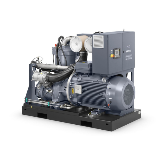
Instruction book General description Introduction General The unit is a single-stage, water-cooled, oil-injected screw compressor, driven by an electric motor. The intended use of the compressor is onboard of a seagoing vessel. General view APF219617... - Page 14 Instruction book General view Electric cabinet Cooling water outlet 15 Control panel Air filter Cooling water inlet 16 Indicator lamp, Motor heaters on Pressure safety valve 10 Oil filters 17 Emergency stop button Unloader 11 Air receiver/oil separator 18 Drive motor Compressor element 12 Skid (Base frame) 19 Manual condensate drain...
- Page 15 Instruction book Start request function Upon a start command (either local or remote) the automatic operation contact will close. This signal will be used by the customer to start a generator. A feedback signal from the generator (closed = ready) is connected to an additional digital input on the Elektronikon module (programmed as permissive start function).
-
Page 16: Air And Oil System
Instruction book Air and oil system Flow diagram Reference Description Atlas Copco installation Customer installation Modulating control Air filter APF219617... - Page 17 Instruction book Reference Description Unloader Oil-injected screw compressor Check Valve Air - oil receiver Oil separator element Safety valve Minimum pressure valve Aftercooler Water separator Oil cooler Thermostatic valve Oil filter with by-pass valve Oil stop valve Drain plug(s) Drain plugs of oil cooler Cock Drain plug (air-oil receiver) Coupling...
-
Page 18: Cooling And Condensate System
Instruction book In air receiver/oil separator (106) most of the oil is removed from the air centrifugally. Almost all of the remaining oil is removed by separator element (107). Cooling and condensate system Cooling system The system is provided with a cooling water system. Condensate drain system A condensate trap is installed downstream of the air cooler to prevent condensate from entering the air outlet pipe. -
Page 19: Modulating Control System
Instruction book solenoid valve (5) is de-energized by Elektronikon regulator (1). The plunger of solenoid valve (5) moves downwards by spring force: Phase Description The plunger of solenoid valve (5) shuts off the supply of receiver pressure towards chamber (2). Control pressure present in chamber (2) is vented to atmosphere through loading solenoid valve (5). - Page 20 Minimum FAD, modulating control : Unit designation Pressure max.FAD min.FAD min.FAD number of d (mm) (bara) (l/s) (l/s) by-pass holes MAS 200 10.4 APF219617...
- Page 21 Instruction book If the air demand drops below the minimum FAD, the net pressure will continue to rise until the unload pressure is reached and the Elektronikon will unload the compressor as on a standard compressor. With a continuing air demand, the net pressure will then drop, until the load pressure is reached and the Elektronikon will let the compressor run loaded.
-
Page 22: Elektronikon® Graphic Controller
Instruction book Elektronikon® Graphic controller ® Elektronikon Graphic controller Control panel ® Display of the Elektronikon Graphic controller Introduction The Elektronikon controller has following functions: • Controlling the compressor • Protecting the compressor • Monitoring components subject to service • Automatic restart after voltage failure (made inactive) Automatic control of the compressor operation The controller maintains the net pressure between programmable limits by automatically loading and unloading the compressor (on compressors running at a fixed speed) or by adapting the... - Page 23 For compressors leaving the factory, this function is made inactive. If desired, the function can be activated. Consult the Atlas Copco Customer Centre. If the function is activated and provided the regulator was in the automatic operation mode, the compressor will automatically restart if the supply voltage to the module is restored.
-
Page 24: Digital Output Contacts
Instruction book Digital output contacts Warning Voltage-free outputs may only be used to control or monitor functional systems. They should NOT be used to control, switch or interrupt safety related circuits. Stop the compressor and switch off the supply before connecting external equipment. Check the Safety precautions. -
Page 25: Icons Used
Instruction book Relay Connector Maximum load 3 X 31 10 A / 250 V AC 10 A / 30 V DC resistive load 3 X 30 10 A / 250 V AC 10 A / 30 V DC resistive load 3 X 30 10 A / 250 V AC 10 A / 30 V DC... - Page 26 Instruction book Compressor status Motor stopped Running unloaded Running loaded Local start / stop Machine control mode Remote start / stop Network control Automatic restart after voltage Automatic restart after voltage failure is enabled failure Week timer Week timer is active Emergency stop Active protection functions Shutdown...
- Page 27 Instruction book Main chart Displayed when chart layout is picked. Menu icons Icon Description Service Alarms (warnings, shutdowns) Week timer Info Test Counters Regulation setpoints Inputs Outputs Event history (saved data) Settings Input icons Icon Description Pressure APF219617...
- Page 28 Instruction book Temperature Digital input, open Digital input, closed Special protection System icons Icon Description Automatic restart (ARAVF) Main chart Compressor element (LP, HP, ...) Filter(s) Motor Expansion module Network settings/problem General alarm Oil circuit Regulation General settings APF219617...
-
Page 29: Main Screen
Instruction book Access key Remote start/stop (Password protected) Navigation arrows Icon Description Down Main screen Control panel Control panel Enter key Cancel / Escape key Scroll keys Function The main screen shows the status of the compressor and is the gateway to all functionality implemented in the controller. - Page 30 Instruction book The main screen is shown automatically when the power is switched on. The display switches to sleep mode when no keys are pushed for a programmable time. Five different main screens can be chosen: 1. Two value lines 2.
- Page 31 Instruction book These icons are always shown in the main screen. If the icon is selected and the Enter key is pushed, the screen jumps to the control mode menu. Following control modes are available: Local control Remote control Network control •...
- Page 32 Instruction book Chart views When the Chart (High Resolution) display is selected, a chart with an X-axis covering 4 minutes is displayed. The value displayed on the Y-axis depends on the selection made in the input screen. Each chart dot represents 1 second. When the Chart (Medium Resolution) display is selected, a chart with an X-axis covering 4 hours is displayed.
-
Page 33: Controller Menu Structure
Please find the tree structure on the 2 top levels below. The items are mentioned as they appear on the screen from top to bottom and left to right. If questions regarding lower levels appear, please consult your local Atlas Copco Customer Centre. SERVICE PLAN... - Page 34 Instruction book Topic Description Displays 4 programmable week action schemes Week Action Schemes Each week action scheme contains 7 programmable days and these days can contain a number of successive events on selected time slots. Contains 10 weeks and each week can be selected as 1 of the 4 week action Week Cycle schemes Status...
- Page 35 Instruction book Topic Description Selection of 1st or 2nd pressure band. A pressure band is a combination of a Pressure band used loading pressure, a setpoint and an unloading pressure Digital pressure band Allows a remote signal to control the pressure band selection. selection Reduced unload pressure...
-
Page 36: Web Server
Instruction book Topic Description General Displays settings concerning time, date, unit and display time-out Only displayed when compressor motor voltage < 690V and when ARAVF is Automatic Restart available. Automatic Restart After Voltage Failure can only be enabled by a service technician. - Page 37 Instruction book • Click on Change adapter settings (1). • Select the Local Area Connection, which is connected to the controller. • Click with the right button and select Properties (1). • Use the check box Internet Protocol version +4 (TCP/IPv4) (1) (see picture). To avoid conflicts, uncheck other properties if they are checked.
- Page 38 Instruction book • Use the following settings: • IP Address 192.168.100.200 (1) • Subnetmask 255.255.255.0 (2) Click OK (3) and close network connections. Configure a company network (LAN) connection • Ask your IT department to generate a fixed IP address in your company’s network. •...
- Page 39 Instruction book • Adapt the network settings in the controller: • Go to Main Menu • Go to Settings (1) • Go to Network (1) APF219617...
- Page 40 Instruction book • Go to Ethernet (1) • Switch Off (1) the Ethernet communication to allow editing the settings • Adapt IP Address (1) • Adapt Gateway IP (2) • Adapt Subnet Mask (3) • Switch On (4) the Ethernet communication APF219617...
- Page 41 Instruction book • Wait a few minutes so the LAN network can connect to the controller Configuration of the web server ® The internal web server is designed and tested for Microsoft Internet Explorer. Also "Opera", "Mozilla Firefox", "Safari"and "Chrome" should work. Viewing the controller data All screen shots are indicative.
- Page 42 Instruction book Navigation and options • The banner shows the unit type and the language selector. In this example, three languages are available on the controller. • On the left side of the interface, you can find the navigation menu. If a license for ESi is foreseen, the menu contains 3 buttons.
- Page 43 Instruction book Info status Machine status is always shown on the web interface. Digital inputs Lists all digital inputs and their status. Digital outputs Lists all digital outputs and their status. Special protections Lists all special protections of the unit. Service plan Displays all levels of the service plan and their status.
- Page 44 Instruction book APF219617...
-
Page 45: Installation
Instruction book Installation Dimension drawing Referenc Description Electric cable entry (can be rotated 180°) Data plate With modulating control 4 slotted holes for horizontally pulling unit out of container (No hoisting) With fully open doors Maintenance separator Manual drain Automatic drain Compressor outlet (10) Cooling water inlet... -
Page 46: Installation Proposal
Instruction book Installation proposal Compressor room example General installation Holes in the cubicle which are not used should be plugged. All electric screens in the control cubicle and drive cubicle have to be installed before start-up and remain installed during operation. APF219617... - Page 47 Drain pipes to condensate collector. The drain pipes may not enter in the collector. Individual drain pipes may not be interconnected, to avoid interference. Compressor condensate contains oil. Depending on local legislation it is recommended to install an oil/water separator (consult Atlas Copco). Control cubicle with monitoring panel. Main cable entry.
-
Page 48: Electrical Connection
Instruction book Reference Description Cooling water inlet pipe. Fit a water shut-off valve and water drain valve in the compressor water inlet pipe and outlet pipe. Remove the plastic plugs (if provided) from the compressor water pipes and connect the pipes to the cooling water circuit. - Page 49 Instruction book Electric connections Electrical diagram APF219617...
-
Page 50: Quality Of Safety Components
Instruction book Reference Description Customer installation Compressor motor Main drive motor 6 fuses (type 2) Additional electric connections Electrical diagram, galvanic barrier Quality of safety components When installing a remote emergency button or a motor contactor, the following B10d values are advised: •... -
Page 51: Position Of Components
Instruction book Connections for external compressor status indication Terminal strip (1X7) is provided with auxiliary contacts for external indication of: Indication Relay Terminals on strip 1X7 Maximum load Automatic operation K05-1 11-12 10 A / 230 V AC General Warning K06-1 13-14 10 A / 230 V AC... -
Page 52: Electrical Cable Size
Cable Cable size Cable voltage selection (A) cable size (mm²) length (mm²) length (m) MAS 200 2x (3x 250) 2x (3x 120+70) 4x (3x 50+25) MAS 200 2x (3x 250 2x (3x 120+70) 4x (3x 50+25) FLA*: Full-Load Ampacity Pictographs... - Page 53 Instruction book Reference Description General alarm Service Automatic operation Voltage on Key to go to previous screen or end current action Key to select parameter (indicated by horizontal arrow) Keys to scroll through the menu Stop Start Other locations Reference Description Oil the gaskets, screw on the filters and tighten by hand (approx.
-
Page 54: Cooling Water Requirements
Instruction book Reference Description Torques for steel (Fe) or brass (CuZn) bolts Consult the Instruction book before greasing Cooling water requirements Recommendations The water circuit must be completely filled up with water at any time. Also when the unit is not running. - Page 55 Instruction book Symbol Explanation Depends on the total solids concentration (mg/l) Depends on the highest cooling water temperature (˚C/˚F), (T=75 ˚C/167 ˚F) Depends on the calcium hardness (ppm CaCO Depends on the HCO concentration or M-alkalinity (mval/l) The values of A, B, C and D can be found in the following table. Total dissolved Temperature Ca-hardness (ppm...
- Page 56 Instruction book Water condition Action 7.6<RSI<9.0 Strong corrosion Regular inspection necessary, use of corrosion inhibitor recommended. 9.1<RSI<11 Very strong corrosion Regular inspection necessary, use of corrosion inhibitor required. RSI>11 Very strong corrosion in Water should not be used. complete water system The table indicates that distilled or demineralized water should never be used, as their RSI is >...
- Page 57 Instruction book Carbonate hardness Closed cooling system : 50-1000 ppm CaCO Open cooling system : 50-500 ppm CaCO / SO should be > 1 Ammonia < 0.5 ppm Copper < 1 ppm Iron and manganese < 1 ppm Organics No algae No oil Suspended solids Non-soluble particles, size <...
-
Page 58: Operating Instructions
Instruction book Operating instructions Initial start-up Warning The operator must apply all relevant Safety precautions. Switch off the voltage before making any adjustment. Outdoor/altitude operation If the compressor is installed outdoors or if the air inlet temperature can be below freezing point, precautions must be taken. - Page 59 Instruction book Step Action Install the compressor, see sections Dimension drawing, Installation proposal Electric cable size. Stick labels near the control panel to warn the operator that: • the compressor may start automatically after a voltage failure • the compressor is automatically started and stopped •...
- Page 60 Instruction book Transport fixtures Step Action The gear casing supports, motor support and air receiver supports are secured to the frame, immobilizing the vibration dampers during transport. Remove the bolts (1) from the gear casing supports and the motor support. Remove the brackets (2) fitted next to the air receiver supports.
-
Page 61: Before Starting
Instruction book Start up Manual condensate drain valve Step Action Close the manual condensate drain valve (3) (see also section Cooling and condensate system). Switch on the voltage. Start the compressor and stop it immediately. Check the rotation direction of the drive motor while the motor is coasting to a stop. -
Page 62: Start Request (Function)
Instruction book Control panel Step Action Switch on the voltage. Voltage on LED (8) lights up. Close the condensate drain valves (see section Cooling and condensate system). Open the air outlet valve. Check the oil level indicator. The pointer should be in the green or orange range. Open the water shut-off valves (if installed) and the water flow regulating valves. -
Page 63: Starting
Instruction book --> customer has 60 seconds to close the contact (min 0 sec - actual 60 sec. - max 255 sec) --> if contact is not closed after preset time: general shut-down (start failure) --> if contact is closed during this preset time: compressor starts and general warning disappears Compressor running : •... - Page 64 Instruction book Step Action Press start button (14). The compressor starts running in unloaded condition. Automatic operation LED (7) lights up. Approx. 10 seconds later (programmable), the compressor starts running loaded. The message on display (1) changes from -Automatically unloaded- to -Automatically loaded-.
-
Page 65: During Operation
• For optimum operation, the cooling water outlet temperature must never exceed the max. value. • Consult Atlas Copco if condensate should be formed during frequent unloading periods. Manual restarting In automatic operation, the regulator limits the number of motor starts. -
Page 66: Checking The Display
Instruction book To put the compressor back into automatic operation, select Load on the display using the cursor keys and press the enter key. • If the motor is stopped and automatic operation LED (7) is alight, the motor may start automatically. -
Page 67: Manual Loading/Unloading
Instruction book Manual loading/unloading Control panel Automatic operation Normally, the compressor runs in automatic operation, i.e. the electronic regulator loads, unloads, stops and restarts the compressor automatically. LED (7) is then lit. Manual unloading To unload the compressor manually, select Unload on display (1) using cursor keys (12) and press enter key (10). -
Page 68: Taking Out Of Operation
Instruction book Control panel Reference Name Press stop button (13). LED (7) goes out. The compressor will run unloaded for 3 seconds and then stops. To stop the compressor in case of emergency, press the emergency stop button. Alarm LED (4) starts flashing. After remedying the trouble, unlock the emergency stop button by pulling it out. -
Page 69: 5.10 Use Of Air Receiver
Instruction book Step Action Disconnect the cooling water pipes from the compressor. 5.10 Use of air receiver Instructions Step Action This equipment can contain pressurised air and oil; be aware of its potential danger if used improperly. This equipment must only be used as compressed air/oil separator and must be operated within the specified limits. -
Page 70: Maintenance
4000 Replace air filter element. Yearly 4000 Replace oil filters. Yearly Carry out a LED/display test (see section Test menu). Yearly Have all flexibles inspected. Yearly Have safety valve tested. (To be carried out by an Atlas Copco representative) APF219617... - Page 71 When displayed Carry out service action according to the displayed service plans. 1) Whichever interval comes first. The local Atlas Copco Customer centre may overrule the maintenance schedule, especially the service intervals, depending on the environmental and working conditions of the compressor.
-
Page 72: Motors
Safety precautions. The data below are valid for an inlet temperature of maximum 45 °C (113 °F)! Consult your Atlas Copco Customer Centre for higher inlet temperatures. Reset the regreasing service warning after regreasing. Also check the motor data plate... -
Page 73: Oil And Oil Filter Change
Instruction book Important Never mix oils of different brands or types. Oil and oil filter change Warning The operator must apply all relevant Safety precautions. Procedure APF219617... - Page 74 Instruction book Air filter Oil level indicator Air receiver Oil filters Air outlet Oil drain plug Position of oil drain plug and hose Oil cooler drain plugs Oil filler plug 10 Oil coolers 1. Run the compressor until warm. 2. Stop the compressor, close the air outlet valve and switch off the voltage. 3.
- Page 75 Instruction book Note Tighten all drain plugs after draining Oil filter change Oil filters 1. Unscrew the oil filters (1). 2. Clean the filter seats of filter housing (3). 3. Oil the gaskets of the new filters and screw the filters into place until the gaskets contact their seats.
- Page 76 Instruction book 2. Remove the oil filler plug. 3. Fill the air receiver with oil until the level reaches the filler opening. 4. Refit and tighten the oil filler plug. 5. Run the compressor loaded for a few minutes to allow the oil cooler by-pass valve to open. 6.
- Page 77 Instruction book 2. On the Menu screen: use scroll keys (12) to move the cursor to the service icon. Press the enter key. Following screen appears: 3. On the Service menu: move the cursor to the action button -Overview- and press the enter key.
-
Page 78: Modulating Control
Instruction book Modulating control Before disassembling any part of the modulating control system, the compressor should be isolated from the air net and depressurized. The flexible coming from the water separator should be disconnected (and of course afterwards reconnected when all the other parts are reassembled). -
Page 79: Storage After Installation
Service kits comprise all parts needed for servicing components and offer the benefits of genuine Atlas Copco parts while keeping the maintenance budget low. All standard service kits are indicated in the relevant Parts Lists. Service kits of special parts will not be supported. -
Page 80: Adjustments And Servicing Procedures
Instruction book Adjustments and servicing procedures Air filters Warning Stop the compressor, close the air outlet valve, press the emergency stop button and switch off the voltage. The operator must apply all relevant Safety precautions. Control panel Position of air filters APF219617... -
Page 81: Coolers
Procedure Keep the coolers clean to maintain the cooling efficiency. If it should be necessary to wash the coolers with a cleaning agent, consult Atlas Copco Customer Centre. Oil separator element Stop the compressor, press the emergency stop button and switch off the voltage. Close the air outlet valve and open the manual condensate drain valve. -
Page 82: Safety Valve
Never run the compressor without safety valves. No adjustments are allowed. Testing The valve can be tested on a separate compressed air line. Consult your Atlas Copco Customer Centre if the valve does not open at the correct pressure (see section Settings of safety valve). - Page 83 Select the corresponding setting in the following table, interpolate when necessary. Compressor Pressure (bar) Voltage (V) Mk5 (0.1 A) F21 (%) MAS 200 4488 MAS 200 4375 MAS 200 4263 2. Use Modi 5 and go to: Config > Expansion 1 > transmitter input 1 > motor current > sensor range Adapt the value in 'maximum' to the selected value (Mk5) from the table.
- Page 84 Instruction book • Example: • Machine = MAS 200 440 V • The value for F21 = 20.7 % • I = 20.7 x 10 = 207 A • 20 mA = (20 - 4) x 207 / 12.8 = 258.75 A → Multiply by 1.73 → The supply current = 447.6 A...
-
Page 85: Modulating Control : Adjusting The Set Pressure Of The Control Valve
Instruction book Modulating control : Adjusting the set pressure of the control valve Before installation modulating control The following procedure can be used to adjust the set pressure of the control valve before installation (with an accuracy of less than 0.5 bar) : •... -
Page 86: Modulating Control : System Components
Instruction book Elektronikon settings The loading and unloading pressure settings of the Elektronikon should comply with the following rules: • The unloading pressure should be at least 0.2 bar higher than the set pressure of the modulating control valve. • The loading pressure should be at least 0.2 bar lower than the set pressure of the modulating control valve. - Page 87 Instruction book If pressure is applied to the actuating cylinder of the throttle valve, the cylinder rod will extract and through a crank open the butterfly valve. At 1 bar control pressure the throttle valve should be fully open. At 4 bar control pressure the throttle valve should be completely closed (except for the by-pass hole(s)).
-
Page 88: Problem Solving
Instruction book Problem solving Problem solving Warning Before carrying out any maintenance, repair work or adjustment, stop the compressor, press the emergency stop button and switch off the voltage. Close the air outlet valve and open the manual condensate drain valves. Open and lock the isolating switch. - Page 89 Multiple shut-down If there are multiple sequential failures with short time intervals on a specific shut-down functionality, consult your Atlas Copco Customer Centre. Excessive oil consumption Have the compressor inspected by your Atlas Copco Customer Centre. Condition Fault Remedy Condensate is not discharged from Discharge pipe of condensate Check and correct as necessary.
-
Page 90: Technical Data
Never run the compressor without safety valves. No adjustments are allowed. Testing The valve can be tested on a separate compressed air line. Consult your Atlas Copco Customer Centre if the valve does not open at the correct pressure (see section Settings of safety valve). -
Page 91: Compressor Data
Instruction book Compressor data Specification Unit MAS 200 (the declared A-weighted emission sound pressure level at dB(A) pWSAd workstation) (the declared A-weighted sound pressure uncertainty in accordance with Clause 8 of EN ISO 2151:2008) (the declared A-weighted sound power level where the A-... - Page 94 This is what we call - Sustainable Productivity. Atlas Copco Airpower Oil-free Air Division, Boomsesteenweg 957, 2610 Wilrijk, Belgium Phone: +32 (0)3 870 21 11 Atlas Copco Airpower NV. All rights reserved. Designs and specifications are subject to change without notice or obligation.
Need help?
Do you have a question about the MAS 200 and is the answer not in the manual?
Questions and answers