Table of Contents
Advertisement
Quick Links
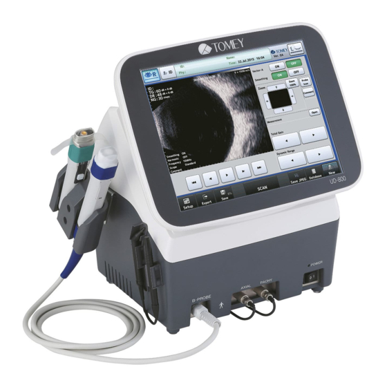
INSTRUCTION MANUAL
ULTRASONIC A/B SCANNER
AND PACHYMETER
Read this manual thoroughly before using the instrument to
ensure proper and safe operation.
Contact Tomey Corporation or your local distributor if you
have any questions or you encounter any problems during
operation.
■
Always follow the operation procedures
described in this manual.
■
Keep this manual in a readily accessible
location while operating the instrument.
■
Contact your local distributor if you lose this
manual.
UD-800
76AA9090-0J
Advertisement
Table of Contents

Related Manuals for Tomey UD-800


Summary of Contents for Tomey UD-800
- Page 1 AND PACHYMETER UD-800 Read this manual thoroughly before using the instrument to ensure proper and safe operation. Contact Tomey Corporation or your local distributor if you have any questions or you encounter any problems during operation. ■ Always follow the operation procedures described in this manual.
- Page 3 Inappropriate wiring may damage the internal circuit. Never touch any of these terminals and the patient at the same time. Be sure to contact Tomey or your local distributor before using the external output terminal. ■...
- Page 4 This page is intentionally left blank. ■...
-
Page 5: How To Read This Manual
ii. How to read this manual Outline This manual is structured as follows. 1. PRIOR TO USE Describes safety precautions and important information to be understood before installing and using the instrument. 2. NAMES AND FUNCTIONS Describes names and functions of each section of the instrument. 3. -
Page 6: Symbols Used In This Manual
Symbols used in this manual Sentences accompanied with the symbols below indicate the following: ■ This is a precaution that, if unheeded, will result in a hazardous situation where there is an imminent danger of serious injury or death. ■ This is a precaution that, if unheeded, could result in a hazardous situation where there is a possibility of serious injury or death. -
Page 7: Table Of Contents
iii. Contents Important safety information ....................i-1 How to read this manual ..................... ii-1 Outline ..............................ii-1 Symbols used in this manual ....................... ii-2 iii. Contents ..........................iii-1 PRIOR TO USE ........................1-1 1.1 Precautions for operation ......................1-1 1.2 Checking package contents ......................1-5 1.3 Glossary ............................ - Page 8 3.2.5 Obtaining ultrasonic image ....................3-14 3.2.6 Various functions ........................3-15 3.3 Biometry function ......................... 3-22 3.3.1 Setting measurement conditions ..................3-22 3.3.2 Operation check........................3-25 3.3.3 Preparation for measurement ....................3-25 3.3.4 Precautions for measurement ....................3-26 3.3.5 Measurement: ........................3-32 3.3.6 Checking waveforms after measurement ................
- Page 9 3.9.1 General ..........................3-74 3.9.2 Measurement ........................3-76 3.9.3 Application ..........................3-81 3.9.4 Connecting & Printing ......................3-83 TECHNICAL INFORMATION ....................4-1 4.1 IOL power calculation formula ....................... 4-1 4.1.1 Haigis optimized / Haigis Standard ..................4-1 4.1.2 Hoffer ® Q formula ........................
- Page 10 6.3 Biometry function ........................... 6-5 6.4 Pachymetry function ........................6-8 CONSUMABLES AND OPTIONAL EQUIPMENT ..............7-1 7.1 Spare parts ............................ 7-1 7.2 Optional parts ..........................7-1 SPECIFICATIONS ........................ 8-1 8.1 Specifications ..........................8-1 8.2 Quantity of ultrasonic energy ......................8-5 8.3 Noise ..............................
-
Page 11: Prior To Use
1. PRIOR TO USE ■ Read this manual thoroughly before using this instrument to ensure proper and safe operation. ■ Always follow the operation procedures described in this manual. ■ Check that there are no devices that generate a strong magnetic field near the instrument. - Page 12 Conduct grounding work correctly. Otherwise, you may get electric shock. Do not connect a device with data transmission specifications that are not compatible. Fire or electric shock may occur. Contact Tomey Corporation or your local distributor before using the instrument while connected to another device.
- Page 13 Do not allow the patient to touch the instrument. If any smoke, offensive odor, or abnormal sound occurs, turn off the instrument immediately, disconnect the power plug from the outlet, and contact your local distributor or Tomey Corporation. ■ Precautions after operation Do not place any container with liquid in it on the instrument.
- Page 14 Disconnect the power cord from the outlet when replacing fuses. Otherwise, you may get electric shock, resulting in death or serious injuries. Use the power cord and fuses provided with the instrument or specified by Tomey to ensure safety. Also, do not use the accessories provided with the instrument for other equipment.
-
Page 15: Checking Package Contents
1.2 Checking package contents Open the package and check that the required quantity of the following items is included and they are not damaged. If any item is missing or damaged, contact your local distributor as soon as possible. ■ Keep the box and packing materials for use when moving or transporting the instrument. -
Page 16: Glossary
[DATA Transfer] : System to output the examination data created by TOMEY products as a file [Export] : To send measurement data to DATA Transfer or Tomey Link. [FREEZE] : Status where ultrasound waves are not transmitted [Immersion] : Measurement mode when applying cornea protective agent between the contact section of the axial length probe and the cornea. - Page 17 [SNR] : S/N (signal to noise) ratio A larger value represents less noise, meaning higher quality signals can be obtained. [TOMEY Link] : Digital medical record system to manage data measured with Tomey products [VD] (Vertex distance) : Distance between corneal vertexes [mm] Represents the distance between the corneal vertex and the posterior surface of the lenses to be prescribed.
- Page 18 [Vector A mode] : Indicates the direction of ultrasonic wave transmission and displays the A mode waveform. [Real time] : Status where ultrasound waves are transmitted ■...
-
Page 19: Overview
1.4 Overview This instrument is designed as an ophthalmology device with functions to retrieve ultrasound topographic images of living tissues using ultrasound waves generated from an ultrasound transducer built into the probe, to retrieve A mode waveforms and to measure axial length and corneal thickness. B mode image diagnosis function ●... - Page 20 This page is intentionally left blank. ■ 1-10...
-
Page 21: Names And Functions
2. NAMES AND FUNCTIONS 2.1 Front of the main unit (1) LCD and touch panel (2) Foot switch (3) Power LED Power switch Biometry probe connector / Pachymetry probe connector (6) Probe (7) Probe holder ■... -
Page 22: Back Of The Main Unit
2.2 Back of the main unit (1) Maintenance switch Our service personnel use this switch for maintenance. Never touch this switch. (2) LAN connector (3) USB-D connector (PC) Connect a personal computer here. (4) Foot switch connector (5) Inlet (6) Fuse holder (7) Connector for external storage media such as USB flash memory, a video printer, and an external ID input device, etc. -
Page 23: Sides Of The Main Unit
2.3 Sides of the main unit (1) Built-in printer ■... -
Page 24: Screen
2.4 Screen 2.4.1 Common items (1) Eye button (eye selection button) (2) Patient information button Moves to the patient information input screen. (3) Patient information field (4) Version Displays the version of the system. (5) "Setup" button Moves to the Setup screen. (6) Print / Export / Save buttons Moves to the Patient List screen. -
Page 25: B Mode Image Diagnosis Screen
2.4.2 B mode image diagnosis screen (Real-time screen) (10) (11) (12) (FREEZE screen) (13) (14) (15) (16) (17) (1) Image monitor Displays an image and the following information. Patient ID, inspection date/time, eye to be examined (R/L), image page No., converted acoustic velocity Total gain (TG) / Dynamic range (DR) / Near gain (NG) Settings for smoothing, harmonic, gradation characteristics, frequencies and scope of the image<... - Page 26 Select the image display depth. Standard / Wide (7) Vector- A tool Operate the Vector-A line. (8) Image Quality Preset values of gains and dynamic ranges. Standard / High contrast / Wide dynamic range (9) Total Gain 20-80dB (10) Dynamic Range 30-70dB (11) Near Gain 1-60step (12) FREEZE / FREEZE cancel button (13) Probe Icon button Displays the probe set angle.
-
Page 27: Axial Length Measurement/View Screen
2.4.3 Axial length measurement/view screen (Measurement screen) (11) (12) (10) (13) (Edit screen) (14) (15) (16) (17) (19) (18) (20) (1) Gain display/adjustment field (2) Mode display – Contact/Immersion (3) Waveform display area (4) The waveform between these two cursors is the waveform of the lens. (5) The waveform on the right of this cursor position is measured as the waveform of the retina. - Page 28 (11) “IOL” button Opens the IOL power calculation screen. (12) Deletes the measurement data currently displayed and measures the same eye again. (13) Axial length measurement data display Displays measurement conditions and measured axial length. (14) Measurement data display The axial length, anterior chamber depth, lens, and their average values are listed.
-
Page 29: Pachymetry Screen
2.4.4 Pachymetry screen (10) (12) (11) (1) Displays the actual measurements of the loaded measurement points. The latest loaded data are displayed during a measurement process. (2) Corneal thickness data display (3) Measurement data display (4) "Delete/Restore" button (5) “Caliper” button (6) “Meas. -
Page 30: A-Diag Measurement Screen
2.4.5 A-Diag measurement screen (Real-time screen) (10) (FREEZE screen) (11) (1) Gain (2) Displays tools for analysis of the line or point. (3) Hold this button briefly to delete “Ref.” data and open the loading screen. (4) “Ref. Wave” button (5) Waveform display area Displays a waveform and the following information. - Page 31 (8) Scale selection Log / Linear / S (9) Select the point to which the probe is applied and the direction of beams that are to be displayed in the waveform display field. (10) FREEZE / FREEZE cancel button (11) "Frame-by-frame" button 2-11 ■...
-
Page 32: Symbols Used For Marking
2.5 Symbols used for marking Refer to instruction manual. “ON” (power) “OFF” (power) Type B attached part Grounding (earth) ■ 2-12... -
Page 33: Operation Procedures
3. OPERATION PROCEDURES 3.1 Preparation before use 3.1.1 Connections ■ The power connector completely isolates the instrument from the commercial power source. If there is a problem with the instrument, turn off the power switch and disconnect the power connector. Install the instrument in a place where this can be performed smoothly. - Page 34 d) Connecting the biometry probe / A-scan diagnosis probe Insert the connector of the biometry probe into the biometry probe/A-scan diagnosis probe connector, indicated by “Axial” on the front of the instrument, in the correct orientation. e) Connecting the pachymetry probe Insert the connector of the pachymetry probe into the pachymetry probe connector, indicated by “Pachy”...
- Page 35 TOMEY Link and DATA Transfer. ■ Connection settings on the Setup screen must be completed in advance to connect with TOMEY Link and DATA Transfer. Refer to “3.9.4 Connecting & Printing” for the setting method. ■ Be sure to make network settings under the consent of your network administrator.
- Page 36 ● Connecting LAN cables Prepare the following items. - LAN cables (straight type, category 5 or higher) - A network hub (A 100MHz switching hub recommended) - A computer with TOMEY Link or DATA Transfer installed (Wiring example) LAN cable Systems in clinic...
-
Page 37: Turning The Power On And Adjustment After Turning The Power On
3.1.2 Turning the power on and adjustment after turning the power on a) Turning the power on Turn on the power switch (1) on the front of the main unit. The startup screen (Fig. 1) appears and then the measurement screen in the mode used last time appears. -
Page 38: Entering The Patient Data
“DATA Transfer” provided with the instrument is not available for query of the patient data. ■ For details on the TOMEY Link Server settings, refer to the TOMEY Link instruction manual. ■ Appropriate connection settings are required for connection with TOMEY Link. - Page 39 (9). Entry method 3: Inquiry to TOMEY Link Enter the ID and touch the “Tomey Link Inquiry” button (3) on the Patient Information screen (Fig. 2). The patient information read from TOMEY Link in the personal computer appears. The inquiry reference can be changed to “DiscomWorkList”...
- Page 40 Entry method 4: External ID input device Data can be entered using a barcode reader, card reader, or keypad. The barcode reader and card reader are also available on the measurement screen in addition to the Patient Information screen (Fig. 2) (Fig.
-
Page 41: Deleting All Measurement Data (Measurement Preparation For Other Patient)
3.1.5 Deleting all measurement data (measurement preparation for other patient) ■ The deleted examination data cannot be restored. Carefully check the data before deleting it. ■ Be sure to touch the “New” button to delete the data for the previous patient before measuring a new patient. -
Page 42: B Mode Image Diagnosis
3.2 B mode image diagnosis Refer to “3.1.3 Switching modes” for how to enter B mode image diagnosis. ■ When the probe is changed, all unsaved data captured by the previous probe is deleted. Be very careful when performing initialization. The instrument automatically detects the connected probe. - Page 43 2) Touch the “OFF” button to hide the probe icon. <Relationship between the displayed image and the probe angle> The B mode probe has a mark (1) that indicates the scanning direction. The relationship between the scan direction mark and the image captured by the probe is as shown below: 10MHz B probe The scan mark = the upper side of...
-
Page 44: Gain Adjustment
<Understanding the probe angle mark> The scan direction mark (1) on the B mode probe is indicated by the extending section (2) of the probe angle mark. (Fig. 4) (Fig. 5) 3.2.3 Gain adjustment ■ Settings made here are only effective for the eye currently selected. Examine the ultrasound image when you make any fine adjustment of the gain. -
Page 45: Patient Preparation
3.2.4 Patient preparation ■ Cooperation by the patient is required to perform examination smoothly. Explain the examination method to the patient before starting the examination to help them relax. ■ Make sure that the air is not mixed in when applying the ultrasound diagnosis gel.When you observe unnecessary echoes, apply sufficient ultrasound diagnosis gel again. -
Page 46: Obtaining Ultrasonic Image
3.2.5 Obtaining ultrasonic image ■ Do not allow water or chemicals to splash on probes, except for the tip cap. Any water or chemicals entering the instrument may cause electric shock or failure. ■ Be sure that the screw is not loose when you use the arm. Otherwise the probe attached to the arm may drop to be damaged or may drop to damage an eye ball or eye lid of the patient. -
Page 47: Various Functions
3.2.6 Various functions Available functions vary depending on the measurement status. See the following table: 10MHz Playing Movie FREEZE Comment FREEZE FREEZE FREEZE Vector-A Smoothing Real-time Real-time Zoom FREEZE Measurement FREEZE Export FREEZE Print FREEZE Save in JPEG Save in USB FREEZE FREEZE memory stick... - Page 48 c) Vector mode-A This function displays captured mode-A waveforms of the image. Please note that the zoom and measurement functions cannot be used when vector mode-A is on. 1) Selecting "ON” for “Vector-A” (1) displays the cursor line and the mode-A waveform for the line position on the monitor.
- Page 49 Smoothing button e) Zoom This function magnifies the displayed image. Vector mode-A cannot be used when zoom is used. The navigation monitor displays the whole image, and the area zoomed in the monitor is indicated by a frame. Moving the frame moves the displayed area accordingly.
- Page 50 1) Open the measuring tool by touching the “Open” button (1) in “Measurement” in the FREEZE menu. 2) Select a tab to display a measurement tool (length, angle, or area). 3) Touching the “Close” button (2) closes the measuring tool screen. [Length measurement] This function measures and displays the distance between two arbitrary points in an image.
- Page 51 [Angle measurement] This function measures and displays the angle determined by three arbitrary points in an image. Touching three points in the image automatically calculates an angle (acute angle) regarding the second point as the center and displays the resultant angle in the image.
- Page 52 g) Harmonic This mode transmits 10MHz ultrasound (fundamental wave) and extracts twofold frequencies (harmonic ingredients) for creation of the image. This mode creates images with better resolution in the azimuth direction (vertical direction in the image) and with less artifacts, providing a more faithful rendering of the tissue.
- Page 53 Full screen display This function zooms the measurement data to the maximum size on the screen. ■ The zoom function is not available while the full screen function is activated. Return to the measurement screen to edit the data. 1) Touch the “FullSize" button (1) to open the Full Size screen. 2) Select a tab to display a measurement tool (length, angle, or area).
-
Page 54: Biometry Function
3.3 Biometry function Refer to “3.1.3 Switching modes” for how to enter biometry mode. 3.3.1 Setting measurement conditions ■ Settings made here are only effective for the eye currently selected. Settings cannot be made for both eyes simultaneously. Complete necessary settings for each eye. Touch the "Setup"... - Page 55 ● IOL eye (acryl) Select this when an acrylic IOL is implanted. ● User Setting Select this when registering optional materials for IOL eyes. Register the settings on the converted acoustic velocity setting screen. (Refer to “3.3.1 b) Setting converted acoustic velocity.”) “Anterior chamber depth”...
- Page 56 Entry boxes (2) for the acoustic velocities required for the eye currently selected appear. Enter the converted acoustic velocity using the software keyboard. After entry, touch the “Enter” key to move to the next entry box. Also, by touching the “Incorporate in L” button (3) or the “Incorporate in R” button (4), the data entered will be applied to the other eye.
-
Page 57: Operation Check
c) Measurement mode Set the measurement mode. ● Auto Select this for normal measurements. ● Auto Quick Select this when measurement is difficult. The conditions for “Measurement Complete”will have greater variation than those of Auto. ● Manual Select this when measurement is difficult in Auto and Auto quick modes. A foot switch is required for measurement. -
Page 58: Precautions For Measurement
3.3.4 Precautions for measurement a) Handling the biometry probe in contact/immersion modes Cornea <Contact mode> Biometry probe Directly apply the contact section of the biometry probe perpendicularly to the center of the cornea. <Immersion mode> When the immersion attachment is not used Ultrasound media Apply the axial length probe perpendicular to the corneal center where corneal protective media, etc. - Page 59 b) Attaching the biometry probe to the applanation tonometer Use the attachment for applanation tonometer provided with the instrument when measuring axial length with the applanation tonometer. Firmly hold the prism attachment section (1) of the applanation tonometer with your fingers so that it does not move. Insert the applanation tonometer attachment (2) into the prism attachment section from the patient side (Fig.1).
- Page 60 Waveform generated Move the cursor to the left in the vitreous of the retina waveform. d) Selecting the waveform on the back of the lens ■ Settings made here are only effective for the eye currently selected. Settings cannot be made for both eyes simultaneously. Complete necessary settings for each eye.
- Page 61 e) What is a good waveform? Depression between retina and sclera (choroid) Retina Sclera Level cursor/line Sharp rise Retina gate cursor (Fig. 1) Lens Axial (anterior length chamber [Contact mode] depth) The instrument recognizes a waveform as a good one if conditions 1) to 3) listed below are satisfied and captures the measurement data in auto measurement mode.
- Page 62 The following is not a requirement for capturing the measurement data, but a method to confirm that the ultrasound wave correctly captures the geometrical axis and ideal waveforms are taken. When the retina waveform spikes, the ultrasound wave reaches the retina perpendicularly.
- Page 63 4) The cornea waveform is formed within 2.0 – 5.0 mm from the initial waveform. (Range between the dotted lines in the illustration) The following is not a requirement for capturing the measurement data, but a method to confirm that ideal waveforms are taken. Check the following together with items i – iv in contact mode.
-
Page 64: Measurement
3.3.5 Measurement: ■ Sterilize the biometry probe before use. ■ Do not use the biometry probe with its contact section damaged.Measurement error may occur, and the cornea may be injured. ■ Immersion attachment is a disposable part.Do not reuse it. Otherwise, you may contract diseases. - Page 65 b) Manual measurement The instrument beeps when the capturing conditions are satisfied. Press the foot switch to capture the measurement data. Press the foot switch again to proceed to the next measurement and take measurements in a similar manner. When 10 data sets are taken, a beep goes off and measurement is completed.
- Page 66 Select a gate cursor to be adjusted by touching the gate selection buttons (1). The selected and active cursor is displayed in red but the other cursors are displayed in white. Touch the gate cursor movement buttons (2) to set the active gate cursor position.
-
Page 67: Checking Waveforms After Measurement
3.3.6 Checking waveforms after measurement a) Displaying waveform of arbitrary measurement data After all necessary measurement data is captured or when the “View” button (1) is touched, the edit screen (Fig. 1) opens. (Fig. 1) The waveform measured at the selection cursor is displayed. Touch the selection cursor movement buttons (2) to move the cursor up or down. - Page 68 c) Gate change function (Fig. 2) Touch the “Gate” button (1) to open the change gate screen (Fig. 2). Touch the gate cursor selection buttons (2) to select the gate cursor to be changed. Touch the “gate cursor movement” buttons (3) to change the position of active gate cursor.
- Page 69 Touch the "Caliper" button (1) to open the caliper screen (Fig. 3). Touch the “Switch” button (2) to select the caliper line to be changed. Touch the caliper line movement buttons (3) to change the active caliper line position. The modified measurement data is displayed in the edit data display field (4) along with the movement of the caliper line.
-
Page 70: Iol Power Calculation
3.4 IOL power calculation ■ When using measurement results for calculation of the IOL power, the physician must examine the measurement result beforehand. ■ Refer to "3.8 Export, print, and save" for waveforms printed and exported from the IOL calculation screen. Touch the "IOL"... - Page 71 Touch the axial length input field (1) or the ACD input field (2) to activate it. Enter the data and touch the “Enter” key to apply the data. [Input range] Axial length : 13.00 - 45.00 mm Anterior chamber depth : 0.00 - 10.00 mm b) Corneal refractive power and radius of corneal curvature (K1/K2) Touch the K1 input field (1) or K2 input field (2) to activate it.
- Page 72 The entered value is stored in the main unit, and is not cleared even when the power is turned off. d) Lens constants (A-constant/SF/ACD-constant/a0・a1・a2) Enter various lends constants for IOL according to the formula. This instrument is able to calculate up to 4 constants for 1 formula simultaneously. The formula (1) corresponds to lenses (2) and (3), and the formula (4) corresponds to lenses (5) and (6).
- Page 73 ■ Entering through IOL data list When IOL data has already been registered in the “IOL data registration,” you can select data from the IOL data list. Touch an input field (1) to activate it. The IOL data list (2) appears. You can check the registration content by sliding the IOL data list being displayed with the scroll bar (3).
- Page 74 e) Entering parameters for Clinical History Method Activated only when SRK/T Double K is selected as the formula. 1) Enter the corneal refractive power or radius of corneal curvature before the surgery for correcting the refractive power in K1pre and K2pre fields. 2) Manually enter eye refractive power before refractive correction surgery in Ref.pre (S,C) (1) and eye refractive power after refractive correction surgery in Ref.post (S,C) (2).
-
Page 75: Setting Calculation Formula
3.4.3 Setting calculation formula Touch the calculation formula pull-down button (1) and select a formula. The following 9 types of IOL power calculation formulae are provided with this instrument. The IOL calculation formulae listed in the pull-down menu can be set as described in “3.9.3 b) Selecting IOL power formula.”... -
Page 76: Entering Data After Surgery
3.4.4 Entering data after surgery Select the name of the IOL type that was actually implanted in the surgery. Select the type of implanted IOL. When the entry field (1) is touched, it is activated. Select the name of the IOL type that was actually implanted in the surgery from the IOL list. -
Page 77: Statistical Processing
3.5 Statistical processing ■ The lens constant registered on this screen will be used for the next IOL calculation. Carefully check the data before registration. Statistical processing can be performed on this screen using the examination data accumulated in the facilities. Predictive errors when using the registered lens constant are calculated and the histogram is displayed. - Page 78 After all the conditions are set, touch the “OK” button (2). Statistical processing is performed and the result appears on the right side of the screen. The histogram (3) in the upper section shows registered lens constants and the statistical processing results of those lens constants. When lens constants are not registered, the result does not appear.
-
Page 79: Pachymetry Function
3.6 Pachymetry function Refer to “3.1.3 Switching modes” for how to enter pachymetry mode. 3.6.1 Setting the data type to be displayed Select the measurement data type to be displayed from the following three options. ● Latest : Displays the last measurement data taken. ●... - Page 80 b) Selecting measurement values to be displayed Select measurement values to be displayed from the following 2 options. ● Actual measurement ● Bias value c) How to display converted acoustic velocity and bias values Select how to display the bias value from the following two options. ●...
-
Page 81: Displaying And Setting Measurement Points
d) Measurement mode Set the measurement mode. ● Auto mode : Select this for measurement in Auto mode. ● Manual mode : Select this when measurement is difficult in Auto mode. 3.6.3 Displaying and setting measurement points Above the horizontal axis Below the horizontal... -
Page 82: Operation Check
(Fig. 1) Touch the input field to activate it. Set values using the keypad and the like. As for the setting of “S/I,” the indication switches between “S” and “I” each time the S/I button (4) is touched. Touch the Preset button (5) to set preset values. (Refer to “3.9.2 d) Measurement setting Axial.”) Touch the “Set”... -
Page 83: Measurement
3.6.6 Measurement: ■ Sterilize the pachymetry probe before use. ■ Do not use the pachymetry probe with its contact section damaged.Measurement error may occur, and the cornea may be injured. ■ The converted acoustic velocity directly affects the measurement data. Check that the desired value is set before starting measurement. -
Page 84: Checking Measurement Data
Step on the foot switch to capture measurement data. A beep sounds when the measurement data is captured. Repeat measurements in the same manner. When 10 sets of measurement data are taken, a beep sounds to indicate completion of measurement. To take measurement data in the next memory slot before 10 sets of measurement data have been taken, touch the next memory number to enter standby mode and perform measurement. - Page 85 Touch the “IOP” button (1) to open the intraocular pressure correction screen (Fig. 1). When a measurement has already been completed at this point, the measured value is displayed in the CCT field (2). However, if measurement points are set and two or more “CCTs” are included in them, the average of the CCTs is displayed.
- Page 86 “Return” button (3). Touch the “Return” button to cancel the deletion. When new measurement data is captured, however, the deleted data cannot be restored by pressing the “Return” button. c) Caliper function The caliper function is for temporary reference and cannot store the callipered data.
- Page 87 measured values are displayed in the data 1 display field (2). The measurement data being stored can be selected as Data 1 or Data 2. Touch the "Memory Data" button (3) to display a list of measurement data stored in a USB memory. (Fig. 4) If a patient ID has not been selected, however, the Preservation Data List screen (a list of patient IDs stored in a USB memory) opens.
-
Page 88: A Mode Diagnosis
3.7 A mode diagnosis 3.7.1 Connecting the probe Connect the A-scan diagnosis probe to the instrument. 3.7.2 Switching to A mode diagnosis function Refer to “3.1.3 Switching modes” for how to enter A mode diagnosis mode. 3.7.3 Registering Ref. Data Load the reference data for line analysis. -
Page 89: Measurement
3.7.4 Measurement: ■ CVCooperation by the patient is required to perform examination smoothly. Explain the examination method to the patient before starting the examination to help them relax. Apply an appropriate amount of cornea protective agent to the contact section of the A-scan diagnosis probe, and apply the probe to the eye to be examined. -
Page 90: Switching Data Display
3.7.6 Switching data display This instrument stores waveforms for up to 100 data sets. Captured waveform data is displayed in order every time the frame advance/retract buttons (1) is touched. 3.7.7 Setting the beam direction Use the beam direction tabs (1) to change the position to apply the probe or the direction of the ultrasound beam, or to display the position of a point of note (with pathological changes, etc.). -
Page 91: Gradation Characteristics Function
3.7.8 Gradation characteristics function When executing line analysis, select “Log, Linear or S” (1) for the gain curve that converts ultrasound waves obtained by receiving ultrasound wave echoes generated from the ultrasound transducer. 3.7.9 Analysis functions a) Line analysis Select “Line Analysis” (1) for Analysis Method. Select “LINE”... - Page 92 b) Point analysis Select “Point Analysis” (1) for Analysis Method. After measurement is completed, the “X” cursor appears on the waveform monitor. Move the cursor by touching the screen or using the cursor movement button (2), and touch the “SetP1” button to set the gain value at the cursor position as P1. Move the cursor to the next point position and touch the “SetP2”...
-
Page 93: Export, Print, And Save
“DATA Transfer” (included in the package) is required for data communication. ■ Refer to the corresponding operation manual for the TOMEY Link and DATA Transfer settings. ■ Connection setting is required for connecting with TOMEY Link and DATA Transfer. - Page 94 In addition, when data is sent to TOMEY Link, all data without ID numbers is regarded as data of the same patient, so must be handled with great care to avoid mishandling.
-
Page 95: Print
3.8.2 Print The printer and printing type can be selected in the system setup. Refer to “3.9.4 b) Selecting and setting printer.” [Printing by built-in printer] ■ Different waveforms are printed depending on the screen in biometry mode. Waveforms to be printed on each screen are as below. Measurement screen: The waveform which is the closest to the average is output. - Page 96 a) Common items Measurement date and time Product Name Clinic ID/Name Address of clinic Patient ID Patient's name Physician's name Printing date/time 10) Character string defined by user 11) Measurement information (10) (11) ■ 3-64...
- Page 97 b) Example printout of axial length Measurement eye (right eye/left eye) Measurement mode Contact immersion Measured eye type Converted acoustic velocity Gain Average axial length Standard deviation of axial length (10) (11) Difference between shortest axial length and longest axial length 10) Average anterior chamber depth 11) Average lens thickness (13)
- Page 98 c) Example printout of corneal thickness Measurement eye (right eye/left eye) Measurement mode / Type of displayed data Converted acoustic velocity Actual measurement in each memory slot Measurement point of measurement data Average of actual measurements Standard deviation of actual measurements Bias value display method and bias rate or correction...
- Page 99 d) Printout of IOL power calculation Measurement eye (right eye/left eye) Axial length ACD (anterior chamber depth) Corneal refractive power or radius of corneal curvature Cornea equivalent refractive index Target Ref. after surgery Parameters printed when SRK/T Double K is selected Formula name IOL model name, manufacturer name 10) Lens constant...
- Page 100 e) Printout of personal constants Measurement eye (right eye/left eye) Post-operation eye refractive power Power of the implanted IOL Axial length ACD (anterior chamber depth) Corneal refractive power or radius of corneal curvature Lens constant Parameters for SRK/T Double K Calculation result ■...
- Page 101 f) Example printout for A-diagnosis Measurement eye (right eye/left eye) Gradation characteristics (Log / Liner / S) Analysis method (Line / Point) Beam direction Acoustic velocity Total gain Analysis result (Ref, Gain, Obj. Gain, ΔdB) Ref. Data waveform Obj. Data waveform 3-69 ■...
-
Page 102: Saved Data Management
3.8.3 Saved data management a) Saving ■ Always enter the ID number when saving the measurement data. ■ Data saved in a USB memory device may be automatically erased after a long period of use. Consider the USB memory as a temporary storage, and make a backup for important data. - Page 103 (Fig. 3) (Fig. 2) When characters are entered in the search field (3), the patient ID and name are searched and the result appears. Touch the patient information button (4) to open the Patient Information screen and check details of the patient information.
- Page 104 c) Deleting saved data ■ When any patient information is deleted, all the measurement data saved with the patient ID is also deleted, regardless of the mode being displayed. Be sure to check the contents saved before deleting them. [Delete all on Database screen] Refer to “d) Database setting”...
-
Page 105: System Setup
3.9 System setup Touch the “System Setup” button (1) on the Setup screen (Fig. 1) in each mode to open the System Setup screen (Fig. 2). (Fig. 1) (Fig. 2) The system setup consists of 4 major categories. ● General …Time, version information, etc. ●... -
Page 106: General
3.9.1 General Set common items here. Select the General tab. (1) System Ver. Displays the version information. (2) Date & Time Set the display format of the date and the date and time. The key pad appears when the input field is touched. (3) Sound Set whether to emit sounds when operating the screen. - Page 107 “1”, the characters from the very beginning are identified as the ID number. (12) Confirmation Select whether to open the patient information confirmation screen when saving or sending the examination data to TOMEY Link. (13) Keyboard Open the keyboard setup screen for patient's name and physician's name.
-
Page 108: Measurement
3.9.2 Measurement Make settings related to measurement on this screen. Select the Measurement tab. a) Measurement Selection: B-Mode 10MHz Touch the “B-Mode 10MHz” button (1) to make settings for 10 MHz ● Starting Condition Set the default condition of the instrument when power is turned on and when the measurement mode is switched. - Page 109 ● Image Quality Setting Open the Image Quality setting screen and set preset values of each gain and dynamic range. Select Standard, High Contrast or Wide Dynamic Range (1). The corresponding control tools appear on the right. Touch the “Apply Current Setting” button (2) to apply the setting values shown on the current screen for each box.
- Page 110 (1) Default Measurement Method Set the measurement method normally used. Contact / Immersion (2) Fix light Select whether the fix light in the biometry probe is turned on or off. ON / OFF (3) Setting Velocity Mean Velocity (M/V) / Sectional Velocity (S/V) (4) Initial Gain Set the gain when axial length mode is started and when a new patient is examined.
- Page 111 (2) Measure Point Opens the measurement setup screen (Fig. 1). (Fig. 1) (3) PreSet1 / PreSet2 Changes the selected preset measurement point. (4) Eye selection Changes the preset measurement point of the selected eye. (5) Radius input field Specify the radius from the center of the measurement point. Touch the input field.
- Page 112 e) Measurement Setting: A-Diag Touch the “A-Diag” button (1) to make settings for “A-Diag.” ● Foot Switch (Two Button) Select functions of the two-button foot switch. All functions selected by one operation of the foot switch are executed. Export: ON/OFF Print: ON/OFF Save : ON/OFF Save JPEG : ON/OFF...
-
Page 113: Application
3.9.3 Application Make settings related to measurement of calculation, correction, etc. Select the Application tab. Registration of IOL data Selection of IOL power Setting of IOP correction formula formula a) Registering IOL data Touch the IOL Constant “Setting” button to open the System Setup – IOL Constant screen (Fig. (Fig. - Page 114 (5) Warning message Displays warnings for determination of a0, a1, and a2. When the “OK” button is touched, the warning message disappears and the input field appears. b) Selecting IOL power formula Select the IOL formula to be used on the IOL power calculation screen. The selected formulae will be displayed in the pull-down menu on the IOL power calculation screen.
-
Page 115: Connecting & Printing
Input range IOP correction formula name Up to 10 characters Parameter 1 0 - 1500 Parameter 2 0.0000 - 1.0000 (2) Indication Unit mmHg / hPa 3.9.4 Connecting & Printing Make settings related to connection, saving, export, and printing on this screen. Select the Connection &... - Page 116 b) Selecting and setting printer The built-in printer, video monochrome printer, video color printer, network printer or data transfer printer can be selected. Touch the “Setting” button to open the Setup screen for each printer. [Built-in] (Fig. 1) (Fig. 2) (Fig.
- Page 117 (3) Header Info. Select items to always be printed. Inspection date and time / Version / Patient's name / Sex / Physician's name / Printing date and time / Patient ID / User-defined character (4) IOL Window (IOL power calculation screen) Make settings for printing from the IOL power calculation screen.
- Page 118 [Video] (1) B/W Reverse (black/white reverse printing) ON / OFF Small Large (2) Print Size Small / Large (3) “Print” button Set the area to be printed in B-Mode Image / Screen [Network printer setting] (1) IP Address Set the IP address of the printer to be connected. Touch the input field to display the keyboard.
- Page 119 [Data transfer printer setting] (1) Connection permission and selection of cable type (2) Login to Tomey Link (3) Host IP address (4) “Connection Test” button (5) Port number (6) Paper size L / A4 / B5 Set this according to the printer setting.
- Page 120 PC setting Make connection settings and DICOM connection settings to export data to a personal computer with TOMEY Link or Data Transfer installed. Touch the “DICOM Setting” button to move to the DICOM setup screen (Fig. 2). (Fig. 1) (Fig.
- Page 121 (8) SCU AE Name Title of DICOM Application Entity. Conforms to the DICOM standard, and is used for communicating connection between AEs for bilateral certification. When registered on the server (SCP), unauthorized access is prevented, and registered users can identify this application on the network. (9) SCP AE Name Set the title of the DICOM Application Entity compatible with the DICOM server (SCP).
- Page 122 ●The initialization function of this instrument only deletes the data. It does not format the external storage media. Use a PC when formatting is necessary. ●The type of format available on the UD-800 is "FAT32." File system: FAT32、 Allocation unit size: Standard Format option: Uncheck "Quick format."...
- Page 123 e)Extension Export Sets whether to output information related to the clinic and measurement techniques. (1) Outputting ON / OFF (2) Clinic ID / Name Set the clinic ID and name. (3) Clinic Address Set the address of the clinic. f) My IP (1) IP Address Selects either of DHCP (dynamic IP) or MANUAL (static IP) in the IP Setting Type.
- Page 124 ■ When only this instrument and the Tomey Link Server or a Setting computer running Data Transfer are connected to the network, Example the following settings can be used. 1) Check the computer IP address. Check and record the IP address and subnet mask of the computer with DATA Transfer installed.
- Page 125 This page is intentionally left blank. 3-93 ■...
-
Page 127: Technical Information
4. TECHNICAL INFORMATION 4.1 IOL power calculation formula 4.1.1 Haigis optimized / Haigis Standard 1. Implanted IOL power (D) 1000 1000 Where: 1000 d = a0 + a1•ACD + a2•L (ACD ≠ 0) d =(a0 –... - Page 128 : Axial length ACD : Anterior chamber depth (mm) REF : Target Ref. after surgery (D) : Vertex distance (mm) = 12 : Implanted IOL power (D) : 0.4···* : 0.1···* * The HAIGIS optimized formula uses the registered a0, a1, and a2 for calculation.
-
Page 129: Hoffer ® Q Formula
4.1.2 Hoffer ® Q formula 1. Implanted IOL power (D) 1336 1000 Where: 1 2. Target Ref. after surgery (D) when wearing glasses 1 Where: 1336 1000 ... - Page 130 3. Personal ACD 1336 Where: 1336 AREF 1 AREF AREF : Refractive power of eye after surgery (D) ■...
-
Page 131: Holladay 1
4.1.3 Holladay 1 1. Implanted IOL power (D) 1000 2. Predicted refractive power after surgery (D) ... - Page 132 AG = 12.5L / 23.45 AG > 13.5 → AG = 13.5 3. Personal SF ・ } Where: AQ = (nc-1) - 0.001AREF {V(nc - 1) - r} BQ = 0.001AREF {L2•V(nc - 1) - r(L2 - V•na)} - {L2(nc - 1) + na•r} CQ1 = 0.001AREF[V{na•r - L2(nc - -1)} + L2•r] CQ2 = 1000na{na•r –...
-
Page 133: Srk-Ii Formula
4.1.4 SRK-II formula 1. Implanted IOL power (D) for emmentropization emme 2. Implanted IOL power (D) for ametropia amet emme 3. Predicted refractive power after surgery (D) emme Where: L<20.0 →... - Page 134 4. Personal A-Constant A = P + AREF・RF + 2.5L + 0.9K - COR Where: AREF: Eye refractive power after surgery (D) : Refractive factor P > 16 → RF = 1.25 P≦ 16 → RF = 1 COR : Correction value L <...
-
Page 135: Srk/T Formula
4.1.5 SRK/T formula 1. Implanted IOL power (D) for emmentropization 1000 emme 2. Implanted IOL power (D) for ametropia 1000 amet ... - Page 136 : Radius of corneal curvature (mm) = {(KI – 1) × 1000}/K : Cornea equivalent refractive index : Implanted IOL power (D) : Vertex distance (mm) = 12 : Aqueous humor and vitreous refractive index = 1.336 : Corneal reflective index = 1.333 4.
-
Page 137: Srk Showa Formula
4.1.6 SRK SHOWA formula 1. Implanted IOL power (D) L < 22.0 :P = A – 2.5L – 0.9K + 1.4 – 1.45REF 22.0≦ L < 24.5 : P = A – 2.5L – 0.9K – 1.67REF 24.5≦ L < 27.0 : P = A –... -
Page 138: Shammas-Pl Formula
4.1.7 Shammas-PL formula ■ This formula is for POST LASIK. 1. Implanted IOL power (D) for emmentropization 1336 emme 0125 1336 2. Implanted IOL power (D) for ametropia 1336 ... - Page 139 4. Personal A-Constant 1336 1336 1336 5835 1336 1336 ...
-
Page 140: Srk/T Double K
4.1.8 SRK/T Double K ■ This formula is for POST LASIK. 1. Implanted IOL power (D) for emmentropization 1000 emme 2. Implanted IOL power (D) for ametropia 1000 ... - Page 141 : Average corneal refractive power (D) before refractive correction surgery = (K1 + K2)/2 : Average radius of corneal curvature (mm) before refractive correction surgery = {(KI - 1) × 1000}/ K : Cornea equivalent refractive index : Average corneal refractive power (D) after refractive post correction surgery = (K1post + K2post)/2...
-
Page 142: How To Calculate Axial Length Using The Biometry Function
4.2 How to calculate axial length using the biometry function 4.2.1 Phakic eye The axial length measurement is obtained using the following formulae. <When using the average acoustic velocity> : Axial length measurement : Average acoustic velocity for axial length : Measurement time <When using the divisional acoustic velocity>... - Page 143 * The acoustic velocity varies depending on materials, makers, and temperature. - Vitreous acoustic velocity : 1,532 m/s - Anterior chamber depth acoustic velocity : 1,532 m/s The axial length measurement is obtained using the following formulae. ...
-
Page 144: Amplifier Characteristics Of The A-Scan Diagnosis
4.3 Amplifier characteristics of the A-scan diagnosis The I/O characteristics of the log amplifier, linear amplifier, and S-curve amplifier selected for the A-scan diagnosis are as shown below. amplifier Output Linear amplifier S-curve amplifier Input 4.4 Ultrasonic wave output ● MI (mechanical index) MI is a parameter that indicates the mechanical effects of ultrasound waves on biological tissue. -
Page 145: Inspection And Maintenance
This warranty also shall NOT apply if the product has not been installed, operated or maintained in accordance with the INSTRUCTION MANUAL of Tomey Corporation (here in after called “Tomey”). Neither seller not Tomey shall be liable for any damages caused by purchaser's failure to follow instruction for proper installation, use and maintenance of product. -
Page 146: Operation Life
5.3 Inspection ■ When there is a problem, correct waveforms or images may not be obtained correctly. Contact Tomey or your local distributor immediately for repair or replacement. ■ Be sure to hold the connector when removing the measurement probe from the main unit. - Page 147 a) Appearance check Check that the contact section of the probe is not damaged. Check that the connector is firmly inserted and the cable is not damaged. b) Cleaning ■ Use absorbent cotton to clean the contact section of the measurement probe.
-
Page 148: Cleaning And Disinfection Of Measurement Probes (For Europe)
Immerse the whole eye cup in alcohol or sodium hypochloride solution (0.5%), rinse them with purified water to completely remove chemicals, and thoroughly dry them. When sterilizing the pachymetry probe with EOG, remove the protective cap from the tip of the probe and put the whole probe in a sterilizing pack. <Sterilization conditions>... - Page 149 ■ A high-pressure steam sterilizer is acceptable only for the immersion attachment. ● The Ultrasound probe (biometry probe, pachymetry probe, and A-scan diagnostic probe) can be disinfected by immersing the contact section of the probe tip in suitable cleaning fluids. ◎...
-
Page 150: Maintenance Of Main Unit
5.4.3 Maintenance of main unit ■ When disconnecting cords, do not apply excessive force on the cord; for example, do not hold and pull the cord to disconnect it. ■ Do not touch the connection terminal surface of the main unit or measurement probe. -
Page 151: Replacing Consumables
Install the fuse holder in the reverse order of removal. 5.5.2 Printer paper ■ Always use genuine TOMEY paper for the printer. Using other types of paper may cause printer failure. ■ Do not pull paper forcibly. Trying to pull the paper out may cause printer failure. -
Page 152: Storing
5.6 Storing ■ Install the instrument in a location free of water or chemicals. Any water or chemicals entering the instrument may cause electric shock or failure. ■ Do not store the instrument in a location where chemicals are stored or gases may occur. -
Page 153: Troubleshooting
6. TROUBLESHOOTING Check the following first when you encounter any problems. If the problem is not solved even after checking the applicable item listed below, contact your local distributor to request inspection and/or repair. ■ Do not remove the cover of the instrument. Otherwise you may get electric shock. - Page 154 The maintenance switch on the side is in the P (up) position. Turn off the power, return the maintenance switch to the down position, and then turn on the power. The whole monitor screen is dark and not easy to see. The brightness of the monitor is low.
-
Page 155: B Mode Image Diagnosis
Nothing is displayed on the screen of this instrument when inputting IDs in the external ID input device. USB cable. Verify that the USB cable of the external ID input instrument is correctly connected to the main unit. For correct connection, refer to "3.1.1 g) External ID input device."... - Page 156 Gel for ultrasound diagnosis is not used or is insufficient. Apply gel for ultrasound diagnosis to the tip of the probe. If the problem is not solved even after the protective agent is applied, apply more. Noise is generated in the peripheral area If there is any source of noise (devices such as a motor, laser surgical equipment, etc.) near the instrument, move it away from the instrument.
-
Page 157: Biometry Function
The instrument enters FREEZE mode although the foot switch is not pressed. The auto freezing function is activated. When there is no entering from a user in the real time mode for a long time, freeze mode is automatically entered. - Page 158 If there is any source of noise (devices such as a motor, laser surgical equipment, etc.) near the instrument, move it away from the instrument. Patient's sight is unstable. Use the fixlight in the biometry probe or on the chin rest to guide the sight of the patient.
- Page 159 When too much cornea protective agent is applied, a gap is formed between the biometry probe and cornea, and the measurement result may tend to be longer. Apply appropriate amount of cornea protective agent. The immersion attachment is used. (In the case of contact mode) Select immersion mode and take measurements.
-
Page 160: Pachymetry Function
The probe error confirmation screen appears when the power is turned on. The biometry probe is not connected correctly. Correctly connect the probe until it is locked. The fixlight in the biometry probe is turned off. Lighting of the fixlight is set to “OFF.” Set to ON as described in “3.9.2 c) Measurement Setting : Axial.”... - Page 161 Check that the converted acoustic velocity is set correctly. (Refer to “3.6.2 c) How to display converted acoustic velocity and bias values.”) The contact section of the pachymetry probe is damaged. If damaged, immediately stop measurement and contact your local distributor. The pachymetry probe is not calibrated correctly.
- Page 162 This page is intentionally left blank. ■ 6-10...
-
Page 163: Consumables And Optional Equipment
7. CONSUMABLES AND OPTIONAL EQUIPMENT 7.1 Spare parts Ultrasound gel Fuse Specify the fuse type as "Fuse for UD-800." Built-in printer paper Specify the paper type as "TOMEY common printer (58 mm)." 7.2 Optional parts 40MHz UBM probe Probe cap membrane Syringe PROBE Arm... - Page 164 This page is intentionally left blank. ■...
-
Page 165: Specifications
8. SPECIFICATIONS 8.1 Specifications B mode image diagnosis 10MHz B-Probe ●Frame rate Basic mode : 20 frame / sec ●Maximum number of pages in a movie 200 pages x 2 ●Image display range Standard : 35.2mm / 52° (at ultrasound velocity=1550 m/sec) ... - Page 166 Biometry / IOL power calculations ●Measurement range Axial length : 15.00 - 45.00mm : 1.80 - 7.00mm Lens thickness : 2.00 - 6.00mm ●Accuracy Measurement Accuracy : ±0.1mm Measurement Resolution : 0.01 mm ●Factory setting of the converted velocity ...
- Page 167 ●IOL power calculation Haigis standard Haigis optimized Hoffer Ⓡ Holladay 1 SRK II SRK/T SRK SHOWA Shammas-PL SRK/T Double K ●Biometry probe Type : Solid state Fix light : Built in the probe, Red LED ...
- Page 168 A-scan Diagnosis ●Measurement range : 60mm ●A-Scan diagnostic probe Type : Solid state Transducer frequency : 10MHz Tip diameter : 6.0mmφ Dimension / Weight : 8mmφ × 100mm / 30g Dimensions and weights ●Dimension : 310(W)×326(H)×214(D) mm ●Weight : 6.0kg Display...
-
Page 169: Quantity Of Ultrasonic Energy
8.2 Quantity of ultrasonic energy Ispta.3 : 17 mW/cm2 or less Isppa.3 : 28 W/cm2 or less : 0.23 or lower Standards for ultrasonic wave output in an eyeball based on the 510(k) guidelines of FDA Ispta.3 : Spatial peak temporal average strength Isppa.3 : Spatial peak pulse average strength : Mechanical index The ultrasound wave output table based on IEC60601-2-37 is as shown below. - Page 170 Index label Non-scan(Aaprt≦1cm Axial Pachy A-Diag Axial Pachy A-Diag Maximum index value 0.175 0.136 0.129 1.8×10 0.449×10 3.6×10 pr,α[Mpa] 0.557 0.629 0.386 P[mW] 0.0373 4.42×10 0.0542 Min.of [Pα(zs),Ita,α(zs)] Z at max.Ipi,α 1.36 0.05 1.36 [cm] deq(zb) fawf[MHz] 10.147 21.362 8.91 10.147 21.362 8.91...
-
Page 171: Noise
8.3 Noise The instrument generates machine noise while operating when: ■ Turning power on ■ Performing self diagnosis ■ Printing out data ■ Using the keys ■ Inserting, detecting, storing data to, and removing a USB memory ■ Generating errors 8.4 Operating environment Operate the instrument under the following environmental conditions. - Page 172 probe except connector, pachymetry probe except connector, A-Scan diagnostic probe except connector) IP47 (the tip of 10MHz B probe, the tip of the biometry probe, the tip of the pachymetry probe, the tip of the A-Scan diagnostic probe) IP21 (40MHz UBM probe except connector, Foot switch) IP27 (the tip of 40MHz UBM probe) Mode of Operation : Continuous operation...
-
Page 173: Declaration Of Conformity To Emc
30cm(12inches) away from the UD-800. It may degrade the performance of the UD-800 if the equipment is located closer. Do not use the UD-800 adjacent to or stacked on other equipment. If it needs to be adjacent to or placed on other equipment, it must be confirmed that UD-800 operates correctly in such location. - Page 174 Cable list Essential Name Specification Length Note AC Power Cord Unshielded 2.5m Accessories Foot Switch Cable shielded 1.6m Accessories USB cable shielded 1.8m Not accessories USB cable shielded 1.2m Not accessories USB cable shielded 1.8m Not accessories B Probe Cable shielded 1.6m Accessories...
- Page 175 <EMISSIONS> Compliance Test Standard <IMM HOME HEALTHCARE ENVIRONMENT Conducted Emissions CISPR 11 Group 1 Class B UNITY Radiated Emissions CISPR 11 Group 1 Class B > Harmonic distortion IEC 61000-3-2 Harmonic Class A Table Voltage fluctuations and flicker IEC 61000-3-3 Complies 【ENCLOSURE PORT】...
- Page 176 Table 2【Test specifications for ENCLOSURE PORT IMMUNITY to RF wireless communications equipment】 Test Maximum IMMUNITY Band Distance Service Modulation frequency power TEST LEVEL (MHz) (MHz) (V / m) Pulse modulation 380 - 390 TETRA 400 18Hz GMRS 460, 430 - 470 土5kHz deviation FRS 460 1kHz sine...
- Page 177 Table 3【Input a.c. power PORT】 IMMUNITY TEST LEVELS Test Standard HOME HEALTHCARE ENVIRONMENT Electrical fast transients IEC 61000-4-4 土 2kV / bursts 100kHz repetition frequency Surges IEC 61000-4-5 土0.5 kV,土1 kV Line-to-line Surges IEC 61000-4-5 土0.5 kV,土1kV,土2kV Line-to-ground Conducted disturbances IEC 61000-4-6 induced by RF fields 0.15MHz - 80MHz...
- Page 178 Table 5【PATIENT coupling PORT】 IMMUNITY TEST LEVELS Test Standard HOME HEALTHCARE ENVIRONMENT ELECTROSTATIC IEC 61000-4-2 土 8 kV contact DISCHARGE 土 2 kV,土4 kV, 土8 kV, 土15 kV air Conducted disturbances IEC 61000-4-6 induced by RF fields 0.15 MHz - 80 MHz 6 V in ISM and amateur radio bands between 0.15 MHz and 80 MHz 80 % AM at 1 kHz...
- Page 179 Fax: +81 52-561-4735 EC-Representative Tomey GmbH Wiesbadener Straße 21 90427 Nürnberg, Germany Tel: +49 911-9385462-0 Fax: +49 911-9385462-20 AUTHORIZED TOMEY SERVICE CENTERS Headquarters, Pacific Rim Tomey Corporation 2-11-33 Noritakeshinmachi Nishi-ku, Nagoya 451-0051 JAPAN Tel: +81 52-581-5327 Fax: +81 52-561-4735 Europe Tomey GmbH Wiesbadener Straße 21...
- Page 180 0120...
Need help?
Do you have a question about the UD-800 and is the answer not in the manual?
Questions and answers