Table of Contents
Advertisement
Read this operator manual completely before attempting to use this instrument in
order to operate it properly and safely.
Do not use procedures other than those specified in this manual.
Keep this operator manual in a place you can access easily.
If you lose this operator manual, contact your Tomey representative.
Contact your Tomey representative if you have any questions or problems.
OPERATOR MANUAL
AUTO REFKERATOMETER
RC-5000
Advertisement
Table of Contents

Related Manuals for Tomey RC-5000


Summary of Contents for Tomey RC-5000
- Page 1 Do not use procedures other than those specified in this manual. Keep this operator manual in a place you can access easily. If you lose this operator manual, contact your Tomey representative. Contact your Tomey representative if you have any questions or problems.
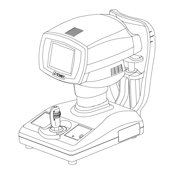
- Page 3 The RC-5000 AUTO REFKERATOMETER is especially designed for measuring eye's re- fractive power and corneal curvature. The RC-5000 provides the additional functions of PD, corneal diameter, pupillary diameter, and CL base curve measurements. Since, however, the measurement quality of these func- tions is not guaranteed, the exclusive equipment designed for respective measurements should be used.
- Page 4 CAUTION LABELS Do not stain or damage the caution labels. If the caution label is stained or damaged, ask Tomey Corporation or your local distributor or representative for its replacement. CAUTION LABELS...
- Page 5 THE STRUCTURE OF THIS OPERATOR MANUAL The structure of this Operation Manual is as follows. 1. PRIOR TO USE Precautions and confirmations for the installation and usage of the instrument. 2. NAMES AND FUNCTIONS OF THE COMPONENTS Names and functional descriptions of the components. 3.
- Page 6 SYMBOLS USED IN THIS OPERATOR MANUAL The symbols used in this manual represent the following meanings. Precaution that, if unheeded will cause a hazardous situa- tion where there is imminent danger of serious injury or death. Precaution that, if unheeded, will cause a hazardous situ- ation where there is possibility of serious injury or death.
-
Page 7: Table Of Contents
Contact lens measurement mode ................3-15 PRINTOUT .............................3-16 3.4.1 Printing-out procedures ....................3-16 3.4.2 Print mode ........................3-17 DISPLAY OF MEMORY DATA ....................... 3-20 DATA MANAGEMENT WITH "TOMEY Link" .................. 3-21 3.6.1 Setup..........................3-21 3.6.2 Receiving of Patient's ID....................3-22 CONTENTS... - Page 8 3.6.3 Sending of measurement data ..................3-23 ID INPUT WITH TOMEY FORM...................... 3-24 SETUP OF MEASUREMENT CONDITIONS .................. 3-25 3.8.1 Setup..........................3-25 3.8.2 Temporary Setup ......................3-32 LANGUAGE SELECTION ......................3-34 REFERENCE TECHNICAL INFORMATION ..............4-1 INSPECTION AND MAINTENANCE ................5-1 WARRANTY ............................
-
Page 9: Prior To Use
Do not connect the instrument to any equipment of which data transfer code is different from that for this instrument. Which may cause inflammation or struck by electricity. In case of connecting this instrument to the communication connector, be sure to consult with Tomey Corporation. 1.1 SAFETY PRECAUTIONS... - Page 10 Tomey Corporation. - Pay attention and carefully to the position of Patient's face and hand or fingers ,When operating Measurement Head and Chin rest.
- Page 11 Care shall be taken on the following items, after using the instrument. - Do not use organic solvents, such as thinner, benzene, and acetone, for cleaning the instrument, which may cause inflammation or struck by electricity. - Do not apply an undue force to the power cord when disconnecting from the receptacle, but hold the plug unit instead.
-
Page 12: Unpacking
1.2 UNPACKING After unpacking, make sure that you have received the fol- lowing items without damages. In the event that any item is found missing or damaged, contact your local distributor. The packing box and the cushion materials should be kept, since they may be necessary, if the instrument is moved or transported to other places. -
Page 13: Glossary
1.3 GLOSSARY [A/AX/AXIS] Astigmatism axial angle [0° to 180°] Represents the angle of astigmatism at which the power is located in the direction crossing the astigmatism axis. [AA] Auto-alignment. [AS] Auto shot. [AVG] Average of strong and weak principal meridians. [BC] Contact lens inner curvature (base curve) [mm] Cylindrical power [D]... - Page 14 [VD] Vertex distance [mm], which represents the distance between the corneal vertex and the posterior of the corrective lens to be pre- scribed. (When VD=CL is displayed, calculation is made for a corneal vertex distance of "0"). [AUTO SHOT] Function by which measurement is automatically started when fo- cusing in the directions of up/down/left/right becomes optimum.
-
Page 15: Outline Of Operations
1.4 OUTLINE OF OPERATIONS The Auto Refkeratometer, RC-5000, is an objective refractive power measuring instrument which provides the ophthalmometry function to measure corneal curvature. The Patient places his chin on the Chin Rest and looks the fixation target through the measurement window. The examiner adjusts the focusing di- rection by moving the Joystick up/down/left/right. - Page 16 This page is intentionally blank...
-
Page 17: Names And Functions Of The Components
2. NAMES AND FUNCTIONS OF THE COM- PONENTS 2.1 EXAMINER'S SIDE MEASUREMENT HEAD Part where measurement is performed. MONITOR/TOUCH PANEL The Measurement screen and various setting screens are displayed. Various settings and operations are also performed by pressing of the touch panel buttons provided in the liquid crystal monitor. - Page 18 HAND REST The Hand Rest is used to place the hand while it is used to turn the Joystick. The Hand Rest is also used for roughly adjusting the Measurement Head front/rear/left/right. (See Section 2.4.) PRINTER Prints measurement results. EYE LEVEL MARK The level of the patient's eye to be measured is adjusted to this mark.
-
Page 19: Patient's Side
2.2 PATIENT'S SIDE MEASUREMENT WINDOW The Patient looks at the fixation target through the Measurement Window. CHIN REST Patient's chin is placed on the Chin Rest. HEAD REST Patient's forehead is placed to the Head Rest. POWER SWITCH The power is turned on by pressing the side of " I (ON)" and turned off by pressing the side of "... -
Page 20: Measurement Screen
2.3 MEASUREMENT SCREEN MEASUREMENT MODES DISPLAY "RK" / "REF" / "KRT" / "DIA" / "CL" Measurement modes (Ref-keratometer "RK" / Refractometer "REF" / Keratometer "KRT" /Corneal diameter·Pupil diameter "DIA" / Contact lens base curve "CL" are displayed. EXAMINATION EYE DISPLAY BUTTON "R" / "L" The Right or Left side of eye being examined is displayed in color. - Page 21 KERATOMETER CORNEAL MEASURING PART DISPLAY "Ø3" / "Ø6" / "Ø3/Ø6" In the Keratometer measurement, the corneal measurement part (center "Ø3mm" / periph- ery "Ø6 mm" / center & periphery "Ø3/Ø6 mm" simultaneous measurement) are displayed. Ø3mm and Ø6 mm are the figures obtained on the assumption that the corneal curvature is 8 mm.
- Page 22 TARGET LUMINOUS SPOT The corneal vertex position of the eye to be examined is indicated. TARGET RING The indicator for positioning the eye to be examined when measurement. MINIMUM PUPILLARY DIAMETER RING The measurable minimum pupil diameter is indicated. AUTO ALIGNMENT RING The effective range of auto alignment is displayed.
-
Page 23: Operating Procedures Of The Joystick
2.4 OPERATING PROCEDURES OF THE JOYSTICK Two ways of Joystick operation, one is for rough adjustment and the other is for slightly adjustment. The Measurement Button is provided at the upper part of the Joystick. <Rough adjustment> Front/rear and right/left Slide the Hand Rest to the expected direction of the Measurement Head. -
Page 24: Touch Alignment
This Connector is used to output measurement data by con- necting it to the LAN adapter of your personal computer or the TOMEY Link. (See "3.6 DATA MANAGEMENT WITH TOMEY Link".) Ask your Tomey's distributor or representative for detail information. -
Page 25: Operating Procedures
3. OPERATING PROCEDURES 3.1 INSTALLING 3.1.1 Precautions for installation Install the instrument in a place where it is free from water and chemicals, if such things are enter into the instrument inside, may cause struck by electricity or system malfunctions. Do not install the instrument in a place where any chemicals are stored or any gas is generated, if such chemicals are spilled or evaporated to enter... -
Page 26: Precautions For Connecting Of The Power Cord
As for the details of removing the Printer cover, see "5.5.1 Replacing of the Printer Paper". In case of using an externally connected Printer, ask Tomey Cor- poration of your distributor or representative. 3.1 INSTALLING... -
Page 27: Preparation For Measurement
Power plug from the receptacle. Next report such abnormal condition to your local distributor, representative, or Tomey Corporation. Do not lay yourself nor apply undue force to this instrument, or it may fall down, also possibly causing instrument damages or personal injuries. -
Page 28: Selecting Of The Measurement Mode And Setting Of The Measuring Conditions
3.2.2 Selecting of the measurement mode and setting of the measuring conditions <Selecting of the measurement mode> Press the Mode Button of the Operation Buttons (Fig. 1), so the mode will change in order of " RK RK ". The selected mode will be displayed in the mode display the Measurement Screen (Fig. -
Page 29: Adjusting Of Patient's Position
3.2.3 Adjusting of Patient's position The Chin Rest is attached with the Chin Rest paper to maintain it cleanly. It is suggested to use the Chin Rest paper so as not to give an uncomfortable feeling to the Patient. Before proceeding to the measurement for the next Patient, first remove the top sheet of the Chin Rest paper and next clean the Head Rest and wipe the Head Rest cleanly with a piece of clean cloth. -
Page 30: Alignment Procedure
3.2.4 Alignment procedure Pay attention and carefully to the position of Patient's face and hand or fingers ,When operating Measurement Head and Chin rest. It may cause p h y s i c a l i n j u r y d e p e n d o n m o v e m e n t o f Measurement Head and Chin rest. - Page 31 7) When Auto Shot is ON, automatically measurement till the number of measurement times which is set. 8) Touch an icon of other side eye (R or L), Measurement Head moves automatically to the other side eye when fin- ish measurement of the one side eye. <When auto alignment is ON>...
-
Page 32: Measurement
3.3 MEASUREMENT Advise the Patient not to blink while measuring eye. If the Patient's eye has too many blinks or such an abnormal condition of corneal disease, not be able to perform measurement by auto shot. If so, try by manual measurement. - Page 33 3) When measurement has been finished, the message of "Fin- ished" is displayed in the screen. If auto shot is active, it will be released from its activated state. <Countermeasures for measurement problems> In case measurement is unable or the error message is dis- played for measurement results, the following problems are possibly caused.
- Page 34 It may not measurement properly for cataract or vitreous hem- orrhage eye which Optic media opacity and the ocular fundus reflective light is extremely small. Press the IOL/CAT button of the operation button (Fig. 4) to select the CAT mode to start measurement.
-
Page 35: Corneal Curvature (Keratometer) Measurement Mode
3.3.2 Corneal curvature (keratometer) measurement mode <Keratometer Measurement Screen> The latest measurement value is displayed in The number of dot in indicate saved measurement data number, and indicate measuring number with latest mea- surement. The colors of measurement data and dots which indicate reliability of measurement. - Page 36 In case the measurement cannot be repeated the set times for some reason, “KRT ?” will be displayed. In this case, mea- surement can be done again automatically by pressing AUTO button or manually by pressing the measurement switch <Countermeasures for difficult measurement> In the event measurement can not be made or the error mes- sage is displayed for any measurement results, such measure- (Fig.
-
Page 37: Refractive Power And Corneal Curvature (Refkeratometer) Measurement Mode
3.3.3 Refractive power and corneal curvature (refkeratometer) measurement mode <Refkeratometer Measurement Screen> The Refkeratometer Measurement Screen shows a refrac- tive measurement value in the left lower part of the monitor and a keratometer measurement value in the right lower part of the monitor. As for these two measure- ments, see "3.3.1 Refractive power (refractometer) mea- surement".) and "3.3.2 Corneal curvature (keratometer) measurement)". -
Page 38: Corneal Diameter And Pupillary Diameter Measurement Mode
3.3.4 Corneal diameter and pupillary diameter measurement mode Acquire the image of the anterior ocular segment and align the cursors to the pupil or both ends of the cornea, to measure the distance between the cursors, with which the sizes of the pupil and the cornea are measured. -
Page 39: Contact Lens Measurement Mode
3.3.5 Contact lens measurement mode This mode is of the function by which the base curve of the hard contact lens is measured. Care shall be taken not to cause air bubbles in the measuring area. Care shall be taken not to cause water or dust to adhere to the measurement surface. -
Page 40: Printout
3.4 PRINTOUT 3.4.1 Printing-out procedures Make sure that the built-in Printer is loaded with the paper roll. (See "5.5.1 Replacing of the Printer Paper") If the Printout for built-in Printer is off at the time of setting data output, printing out cannot be made. Set the printing out of the built-in Printer ON, by referring to "3.8.1 Setup". -
Page 41: Print Mode
No print is made. Enable * Oculogram is printed. Eye Print Disable No print is made. Enable * Product name (RC-5000) is printed. Product Name Disable No print is made. Normal * Printing is made in the normal line spaces. Line Space Narrow Printing is made in narrowered line spaces. - Page 42 <Printout example A> Printing all the items. Patient’s name Measuring date and time Measuring number Measured eye Refractometer display Corneal vertex distance Refraction values Representative value Data reliability coefficient 10 levels (0 to 9 ) display The higher reliability with the smaller number Error message Low reliability data "e"...
- Page 43 <Printout example B> Printing the following items. R/L separation Disabled Refractometry values No average Keratometry values No avarage Keratometry data form K1K2, No dioptory Patient’s name Measuring date and time Measuring number Measured eye Refractometer display Corneal vertex distance Refreactometry values Representative value Data reliability coefficient 10 levels (0 to 9 ) display...
-
Page 44: Display Of Memory Data
3.5 DISPLAY OF MEMORY DATA This function displays various measurement data saved in the memory in the Monitor. Pressing of the Clear button deletes all the data saved in the Memory. If measurement is given after measured data has been printed out, such printed out data will be deleted from the Memory. -
Page 45: Data Management With "Tomey Link
3.6 DATA MANAGEMENT WITH "TOMEY LINK" Tomey's TOMEY Link (including the LAN adapter) is con- veniently used for data management which corresponds to the computer network. If the TOMEY Link is connected to external equipment other than the LAN Adapter (LA-100), observe the following requirements, which may otherwise cause struck by electricity . -
Page 46: Receiving Of Patient's Id
A Patient's ID is received from the LAN Adapter even if the instrument is in the state of auto power off, if the TOMEY Link has once been selected. 1) Enter a Patient's ID from the LAN Adapter with the Input Patient's ID screen of the instrument as being dis- played. -
Page 47: Sending Of Measurement Data
The TOMEY Link is able to receive a Patient's ID through the LAN Adapter, even if the instrument is in the state of auto power off, as long as the TOMEY Link has been selected. 1) By pressing the TOMEY Link button after measure- ment is finished, the "Patient Information, Send data... -
Page 48: Id Input With Tomey Form
With TOMEY FORM for data output the measured data can be transferred through RS-232C port by setting as in Fig. 1. When TOMEY Link button on the base is pressed after setting this way, The key display for patient's ID input will be shown on the display... -
Page 49: Setup Of Measurement Conditions
3.8 SETUP OF MEASUREMENT CONDITIONS 3.8.1 Setup The operating conditions are set, which will be effective as long as the set up conditions are not changed. Before changing the setup conditions, always press the Save & Exit button to finish the operation. If the operation is finished with the Cancel button, the setup conditions will be returned to the previously setup screen, without saving the... - Page 50 a) Common 1: Common setup 1 Items common to each measurement mode are set up. Auto Power Off 5min: If no operation continues for 5 minutes, the Power Off will be actuated. 10min: If no operation continues for 10 minutes, the Power Off mode will be actuated.
- Page 51 b) Common 2: Common setup 2 Items common to each measurement mode are set up. Time Adjust Adj.: Date and time are set. Pressing of the Adj button displays the Time Adjust Screen (Fig. 2). If each Date and Time column touched, its display will be a changeable condition.
- Page 52 c) REF Setup: Refractometer setup Refractometer measurement conditions are set up. Measurement Times 3: When Auto Shot is ON, 3 consecutive measurements will be made. 5: When Auto Shot is ON, 5 consecutive measurements will be made. High Speed ON: The High Speed mode is enable. OFF: The High Speed mode is disable.
- Page 53 d) KRT Setup: Keratometer setup The measurement conditions for keratometer measurement are set up. Measurement times 1: One measurement is made when Auto Shot is ON. 3: Three consecutive measurements are made when Auto Shot is ON. Unit mm: Keratometer measurement values are displayed in mm unit.
- Page 54 e) Output Setup The output of the measured data is set. Print The measured data is printed by built-in printer. OFF: Printing is disable. Auto Print The Auto Print function is enable. OFF: The Auto Print function is disable. (Fig. 1) Print Form The print mode of the built-in printer is set.
- Page 55 (Fig. 5) The product name is selected by pressing the Edit button on the 3/4screen (Fig. 6). (Fig. 6) External communication TOMEY Link: Connects to TOMEY Link for data commu- nication. Ref Tester: Connects to Ref Tester for data communica- tion.
-
Page 56: Temporary Setup
3.8.2 Temporary Setup Please us the CL data just as a reference for selecting the trial lens in contact lens fitting. Please make sure fitting inspection when fitting contact lenses. Please be sure that the auto fogging is released only in the case the accommodation can be ignored. Otherwise accommodation will be Included in refractory data. - Page 57 AutoFogging Auto fogging which is used to reduce the accommodation can be released temporarily. In case refractometry is difficult because of too much nystagmus and poor fixation, make the measurement time of refractometry shorter by releasing the Auto Fogging temporarily. Disable : Auto Fogging is temporarily released.
-
Page 58: Language Selection
3.9 LANGUAGE SELECTION RC-5000 has Multilanguage function. You can select your favor- ite one from "English", "Japanese", "German", "Chinese", "Span- ish", "Spanish Latin America", "Italian", "Portuguese", "French" and "Russian". Press the Setup button in the Touch Panel to change the screen to the Setup screen. -
Page 59: Reference Technical Information
The total corneal refractive index is determined by the sum of anterior and posterior refractive powers. Since this instrument (RC-5000) mea- sures the curvature of the corneal anterior part, the refractive power of the whole cornea cannot be obtained. - Page 60 This page is intentionally blank...
-
Page 61: Inspection And Maintenance
OPERATOR MANUAL of Tomey Corporation (here in after called "Tomey"). Neither seller not Tomey shall be liable for any damages caused by purchaser's failure to follow instruction for proper installation, use and maintenance of prod- uct. -
Page 62: Life Of Product
5.2 LIFE OF PRODUCT The life of this product is eight years if used in proper atmoshere and with suitable maintenance. 5.3 INSPECTION For measuring the model eye, make sure that it is free of dust and stain adhesion. In order to check to see if the internal functions of this instrument properly work and maintain their performance, check working condition of this instrument with an accessory model eye before use this instrument. -
Page 63: Routine Maintenance
5.4 ROUTINE MAINTENANCE Do not apply undue force to the Power Cord by hold- ing the Cord itself, but hold the plug, when you dis- connect it from the receptacle. The core wires in- side of the Cord may otherwise be damaged, possi- bly causing struck by electricity or inflammation. -
Page 64: Replacing Of Spare Parts
5.5 REPLACING OF SPARE PARTS 5.5.1 Replacing of the Printer Paper Sufficient care shall be given not to touch the Printer cutter with your hand. Do not also cause your Pa- tient to touch the cutter, which may otherwise harm you and Patients. -
Page 65: Replacing Of The Fuse
Be sure to use the fuse specified for the RC-5000. If any operation failure occurs after the fuse has been replaced, other troubles may have caused the failure. Then, turn the power off immediately and report such failure to your local distributor or representative. -
Page 66: Storing
5.6 STORING Store the instrument in a place where it is free of water and chemicals. If such a thing enters the in- ternal part of the instrument, struck by electricity or malfunction may be caused. The instrument shall not be stored in a place where chemicals are stored or any gases are generated. -
Page 67: Disposal Of Packing Materials
5.7 DISPOSAL OF PACKING MATERIALS The packing materials used for shipping of the in- strument will be necessary when the instrument is moved or transported to other places. Therefore, do not dispose them. The cushion materials used for packing of the in- strument should also be stored together with pack- ing materials. - Page 68 This page is intentionally blank...
-
Page 69: Troubleshooting
6. TROUBLESHOOTING Before you conclude your problem as a functional trouble, check the following items. If any problem cannot be cor- rected by the following countermeasures, consult your local distributor or representative. Do not remove the Main Unit Cover of this instrument. You may be exposed to high voltage. - Page 70 The Power switch is ON, but the Monitor is off. Cause 1 The Auto Power Off function (which turns the Monitor off, if operation suspends for a certain period of time) is being activated. Touch the Monitor screen. Remedy No print out can be made with the built-in Printer. The Printer paper ran out.
- Page 71 "Internal Battery Empty" is displayed. The Internal Battery power has run out. Cause 1 Ask your distributor for a new Internal Bat- Remedy tery for replacement. "Calender/Clook Error" is displayed. The Date/Time Function has the problem. Cause 1 Remedy Ask your distributor for correction. "Refractometer Error"...
- Page 72 "Unknown Error" is displayed. A problem which cannot be specified arose. Cause 1 Discontinue your operation and consult your Remedy distributor. 6. Troubleshooting...
-
Page 73: Spare Parts
7. SPARE PARTS As for your purchasing of the following supply parts, please ask your local Tomey's distributor or representative for order placement. Built-in Printer paper Specify "Printer paper for RC-5000 built-in Printer". Chin Rest paper (100 sheets/set) Fuses Specify "Fuses for RC-5000". - Page 74 This page is intentionally blank 7. SUPPLY PARTS...
-
Page 75: Specifications
8. SPECIFICATIONS 8.1 SPECIFICATIONS 8.1.1 Refractive power measurement Spherical refractive power (S) Measurement range: -25.00D to +22.00D (at VD=12.0mm) Display unit: 0.01D / 0.12D / 0.25D Cylindrical refractive power (C) Measurement range: 0D to ±10.00D (at VD=12.0mm) Display unit: 0.01D / 0.12D / 0.25D Astigmatism axial angle (A) Measurement range: 0°... -
Page 76: Pupillary Distance Measurement
8.1.3 Pupillary distance measurement Measurement range: 50 to 86mm Display unit: 8.1.4 Corneal diameter and pupillary diameter measurement Measurement range: 1.0 to 14.0mm Display unit: 0.1mm 8.1.5 Observation range Approximately 15mm x 9mm 8.1.6 Auto-alignment range Up-down / left-right directions: Ø7 mm Focusing direction: ±5 mm... -
Page 77: Noise Occurrence
8.2 NOISE OCCURRENCE This instrument makes noises at the following operations. when turning the power on. when starting printout when moving the measuring area when adjusting the Chin Rest when carrying out measurement (while taking measurement data) 8.3 ENVIRONMENTAL CONDITIONS This instrument shall be used in the following environmental conditions. -
Page 78: Emc Compatibility Declaration
GUIDANCE AND MANUFACTURER'S DECLARATION ON ELECTROMAGNETIC EMISSIONS Table 201 This RC-5000 is intended for use under the following electromagnetic conditions. The customer and the user of the RC-5000 are advised to guarantee the following use conditions of said instru- ment. Emission test Compatibility... - Page 79 GUIDANCE AND MANUFACTURER'S DECLARATION ON ELECTROMAGNETIC IMMUNITY Table 202 The RC-5000 is intended for use in the following electromagnetic environments. The customers and the user of the RC-5000 is advised to guarantee the following environments. Immunity test IEC 60601 Test...
- Page 80 GUIDANCE AND MANUFACTURER'S DECLARATION ELECTROMAGNETIC IMMUNITY Table 204 The RC-5000 intended for use in the following electromagnetic environments. The customer and the user of the RC-5000 is advised to guarantee its use in the following environments. Immunity test IEC 60601 Test Compatibility...
- Page 81 The RC-5000 is intended to be used in the electromagnetic environments where the radiation interference is provided. The customer or the user of the RC-5000 will be able to contribute to the prevention of electromagnetic interference by maintaining the minimum distance between the portable or movable type RF-communication equipment (transmitter) and the RC-5000.
- Page 82 This page is intentionally blank...
- Page 83 Fax: +81 52-561-4735 EC-Representative Tomey GmbH Am Weichselgarten 19a 91058 Erlangen GERMANY Tel: +49 9131-77710 Fax: +49 9131-777120 AUTHORIZED TOMEY SERVICE CENTERS Headquarters, Pacific rim Tomey Corporation 2-11-33 Noritakeshinmachi Nishi-ku, Nagoya 451-0051 JAPAN Tel: +81 52-581-5327 Fax: +81 52-561-4735 Europe...
- Page 84 0123 ID: 0604...
Need help?
Do you have a question about the RC-5000 and is the answer not in the manual?
Questions and answers