Table of Contents
Advertisement
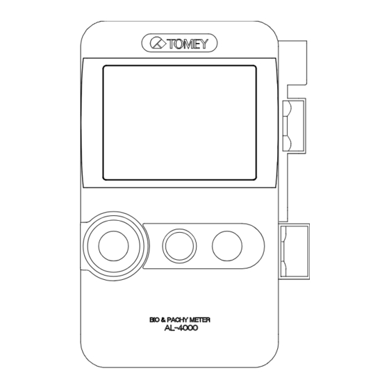
INSTRUCTION MANUAL
BIO & PACHY METER
Read this manual thoroughly before using the
instrument to ensure proper and safe operation.
Contact Tomey Corporation or our local distributor if
you have any questions or you encounter any
problems during operation.
AL-4000
Always follow the operation procedures
described in this manual.
Keep this manual in a readily accessible
place while operating this instrument.
Contact our local distributor if you lose
this manual.
716A9090-10
Advertisement
Table of Contents

Related Manuals for Tomey AL-4000


Summary of Contents for Tomey AL-4000
- Page 1 BIO & PACHY METER AL-4000 Read this manual thoroughly before using the instrument to ensure proper and safe operation. Contact Tomey Corporation or our local distributor if you have any questions or you encounter any problems during operation. Always follow the operation procedures described in this manual.
- Page 3 Inappropriate wiring may damage the internal circuit. Never touch any of these terminals and the patient at the same time. Be sure to contact Tomey or our local distributor before using the external output terminal. When operating this instrument connected to other devices, only use devices...
- Page 4 Never mark or damage the caution labels on the instrument. The caution labels are provided at two locations as shown below. If a label is damaged or becomes illegible, please contact Tomey Corporation or our local distributor.
- Page 5 This device complies with FCC RF radiation exposure limits set forth for an uncontrolled environment. The antenna used for this transmitter must be installed to provide a separation distance of at least 20 cm from all persons and must not be co-located or operated in conjunction with any other antenna or transmitter.
- Page 6 This page is intentionally blank...
-
Page 7: How To Read This Manual
ii. How to read this manual Outline This manual is structured as follows. 1. PRIOR TO USE Describes safety precautions and important information to be understood before installing and using the instrument. 2. NAMES AND FUNCTIONS Describes names and functions of each section of the instrument. -
Page 8: Symbols Used In This Manual
Symbols used in this manual Sentences accompanied with the symbols below indicate the following: This is a precaution that, if unheeded, will result in a hazardous situation where there is imminent danger of serious injury or death. This is a precaution that, if unheeded, could result in a hazardous situation where there is a possibility of serious injury or death. -
Page 9: Table Of Contents
iii. Table of contents i. Important safety information ................... i-1 ii. How to read this manual ..................ii-1 Outline ..........................ii-1 Symbols used in this manual .................... ii-2 iii. Table of contents ....................iii-1 1. PRIOR TO USE ..................... 1-1 1.1 Precautions for operation .................. - Page 10 3.2.7 Clear all measurement data (preparation for measuring a new patient) ..3-22 3.2.8 Selecting the eye to be measured ..............3-23 3.3 Axial length measurement function ............... 3-24 3.3.1 Connecting the biometry probe ..............3-24 3.3.2 Setting axial length calculation method and converted acoustic velocity for eye to be measured ....................
- Page 11 3.7 Utilities ........................3-90 3.7.1 Buttons and icons on the screen ..............3-91 3.7.2 Operations for each setting................3-95 4. TECHNICAL INFORMATION ................4-1 4.1 IOL power calculation formula ................. 4-1 4.1.1 SRK-II formula ....................4-1 4.1.2 SRK/T formula ....................4-2 4.1.3 HOLLADAY formula ..................
- Page 12 8. SPECIFICATIONS ....................8-1 8.1 Specifications ......................8-1 8.1.1 Biometry/IOL power calculations ..............8-1 8.1.2 Function of pachymetry ................... 8-2 8.1.3 A-scan Diagnosis ..................... 8-3 8.1.4 Main unit......................8-3 8.1.5 AC adapter ....................... 8-3 8.1.6 Battery ......................8-3 8.2 Energy and other consumption ................8-4 8.2.1 Influences of ultrasound energy on the human body ........
-
Page 13: Prior To Use
1. PRIOR TO USE Read this manual thoroughly before using this instrument to ensure proper and safe operation. Always follow the operation procedures described in this manual. Do not place any other objects on this instrument. Check that there are no devices that generate strong magnetic field near the instrument. - Page 14 Do not connect a device with data transmission specifications that are not compatible. Fire or electric shock may occur. Contact Tomey Corporation or our local distributor before using the instrument while connected to another device.
- Page 15 A magnet is built into the instrument. Do not place any electronic device, magnetic card, and other objects that may be affected by magnetism near the instrument. These may become unusable. Precautions before operation Check the electrical contact of switches, polarity, dial setting, and meters, and that the instrument is working correctly.
- Page 16 If any smoke, offensive odor, or abnormal sound occurs, turn off the instrument immediately, disconnect the power plug from the outlet, and contact our local distributor or Tomey Corporation. Precautions after operation Do not place any container with liquid in it on the instrument. Any liquid entering the instrument may cause electric shock or failure.
- Page 17 Touching this section will result in death or serious injuries. Use the AC cord provided with the instrument or one specified by Tomey to ensure safety. Also, do not use the accessories provided with the instrument for other equipment.
-
Page 18: Glossary
1.2 Glossary [ACD] Anterior chamber depth [Acrylic] Acrylic lens [Aphakic Aphakic eye [AVG] Average value [Axial Axial length measurement (biometry) [A-Diag] A-scan diagnosis [BD address] Bluetooth® Device Address Number set to each device to identify the connection [Bluetooth ®] Registered mark of Bluetooth SIG, Inc. [Calibration] Calibration of the pachymetry probe [CCT]... - Page 19 [Auto power off function] The power turns off automatically when no operation is conducted for a specified time. [Caliper] Manually moves the measurement point. [Gain] Adjusts amplification and amplitude of waveforms. [Gate] Specifies the range of waveforms to be detected. [Measurement point] Indicates the point where corneal thickness is measured by diameters and angles.
-
Page 20: Checking Package Contents
Keep the box and packing materials for use when moving or transporting the instrument. Main unit BIO & PACHY METER AL-4000 ....1 Biometry probe (with protective cap and the case) ..1 Footswitch..............1 ... -
Page 21: Overview
1.4 Overview ● This instrument is a device used in ophthalmology to measure the distance between living tissue, utilizing ultrasound waves generated from the ultrasound transducer built into the measurement probe. This device is designed to measure the axial length and corneal thickness at optical clinics. The A-scan diagnosis allows you to identify areas with pathological changes by observing mode-A waveforms. - Page 22 This page is intentionally blank 1-10...
-
Page 23: Names And Functions
2. NAMES AND FUNCTIONS 2.1 Front of the main unit (1) LCD and touch panel Measurements, waveforms, and IOL calculation results are displayed on the 3.5” TFT color LCD (320 x 240 dots). Operations are performed by touching buttons on the touch panel attached over the LCD. - Page 24 (6) Power switch Turns the instrument on and off. (7) Gain adjustment knob Knob to adjust the gain...
-
Page 25: Back Of The Main Unit
2.2 Back of the main unit (1) Battery cover Open this cover when replacing the built-in battery. (2) Stand Stand to hold the main unit at an angle (3) Touch pen Used when operating the touch panel. -
Page 26: Sides Of The Main Unit
2.3 Sides of the main unit (1) AC adapter/footswitch connector Connect the AC adapter and footswitch here. (2) Maintenance switch Our service personnel use this switch for maintenance. (3) Cable hook Wind the probe cable that can be stored in the main unit here. -
Page 27: Top Of The Main Unit
2.4 Top of the main unit (1) USB connector Connect the personal computer and IOL calculation unit here. (2) Power supply terminal Receives power supplied from UD-8000. -
Page 28: Bottom Of The Main Unit
2.5 Bottom of the main unit (1) Connector for fixlight Connect the external fixlight of the special chin rest here. (2) Biometry probe connector Connect the biometry probe here. (3) Corneal thickness/A-scan diagnosis probe connector Connect the pachymetry probe or A-scan diagnosis probe here. -
Page 29: Screen
2.6 Screen 2.6.1 Basic structure and common items The dark area varies depending on operation modes. (1) Inspected eye Touch the “R” or “L” button to display the measurement screen for the selected eye (right or left). (2) Patient information field Displays the patient ID entered on the patient information entry screen. - Page 30 Communication stopped : Communication not * Operations not possible. possible Utility operations are required for connection. (6) “Save” button Saves the measurement data in the AL-4000 measurement unit. (7) “Utility” button Opens the utility screen. (8) Battery indicator Shows the battery status.
-
Page 31: Axial Length Measurement (Biometry)
2.6.2 Axial Length Measurement (Biometry) a) Measurement screen (10) (14) (16) (15) (11) (12) (13) (1) Gain indicator Displays the gain. (2) Mode display Displays the mode set on the utility screen (contact or immersion). (3) “Setting” button Displays the measurement condition setting menu. (4) Axial length data display Displays the average, standard deviation, and data range of the axial length. - Page 32 (6) Level cursor/level line Measurement data will be taken when the waveform rises above this cursor/line position. (7) Measurement cursor/measurement line The distance at this cursor/line should be taken as the measurement data. (8) Average acoustic velocity Displays the average acoustic velocity when calculating the axial length. (9) Cursor button Switches the active gate cursor.
- Page 33 b) Edit screen (data list) (1) Measurement data display Measurement data of the axial length, anterior chamber depth, and crystal lens thickness, and their averages are listed. The following marks are assigned to the measurement data. “*”: Data used for calculating IOL L : Longest axial length S : Shortest axial length C : Calipered data...
- Page 34 (6) “Sel (select)” button Selects the data at the cursor position to be used for calculating the IOL. “*” is assigned to the selected data. 2-12...
- Page 35 c) Edit screen (waveform) (1) Memory number selection key Touch these buttons to select the memory number of the measurement data. (2) Waveform, memory number, mean velocity, and eye type of the selected measurement data The waveform, memory number, mean velocity, and eye type of the selected measurement data is displayed.
- Page 36 d) IOL calculation screen (1) Parameter field Enter the following parameters used for calculating IOL power. Axial length / anterior chamber depth / K1 (mm or D) / K2 (mm or D) / Desired refractive power. The anterior chamber depth is displayed only when “HAIGIS standard formula” is selected.
-
Page 37: Corneal Thickness Measurement
2.6.3 Corneal thickness measurement a) Measurement screen (10) (11) (12) (1) Setting display The bias value and types of data to be displayed are listed. (2) Average and standard deviation of corneal thickness The average and standard deviation of the corneal thickness data is displayed. (3) Measurement data display The memory number, measurement data, and measurement point are displayed. - Page 38 (6) “Wave Form” button Displays the waveform of the selected memory number. (7) “Del/Ret” button Deletes or retakes the data. (8) “Meas Point (measurement point)” button Shows and hides measurement points. (9) “Pre 1”/”Pre 2” buttons These buttons appear when the “Meas Point” button is touched and allow you to show the contents preset for the selected measurement point in the measurement data field.
-
Page 39: Diagnosis In Mode A
2.6.4 Diagnosis in mode A a) Measurement screen (real time) (10) (12) (11) (1) Gain display The gain setting is displayed. (2) Log (gradation characteristics) The gradation characteristics are displayed. (3) “Setting” button Shows the measurement condition setting menu. (4) Analysis tool Analyzes waveforms of the measurement data. - Page 40 (7) Measurement waveform The mode-A waveform is displayed. (8) “Save” button Saves the measurement data in the AL-4000 measurement unit. (9) “FREEZE” button Changes the mode from real time to freeze. (10) Probe display The probe type currently applied is shown.
- Page 41 b) Measurement screen (FREEZE) (1) Page button and page number display Changes each data of the captured mode-A waveform. The page number currently displayed is shown. (2) “Edit” button Displays the edit menu. (3) “Release” button Changes the mode from freeze to real time. 2-19...
-
Page 42: Auto Power Off Function
2.7 Auto power off function This function automatically turns off the LCD when the instrument is not operated for a specified time. Touch the monitor to return to normal status. When the AC adapter is not connected, the power is automatically turned off when the specified time has passed after the auto power off function was activated. -
Page 43: Operation Procedures
3. OPERATION PROCEDURES 3.1 Safety precautions Sterilize measurement probes before use. Do not use a measurement probe with its contact section damaged. Measurement error may occur, additionally the corneal or eyelid may be injured. The immersion attachment is a disposable part. Do not reuse it. -
Page 44: Precautions For Installing The Instrument
3.1.1 Precautions for installing the instrument Install the instrument in a location free of water or chemicals. Any water or chemicals entering the instrument may cause an electric shock or failure. Do not install the instrument in a location where chemicals are stored or gases may occur. -
Page 45: Precautions For Connecting The Power
3.1.2 Precautions for connecting the power Check that the frequency, voltage, and allowable current (or power consumption) of the power source are appropriate. Otherwise, fire or electric shock may occur. Do not place any heavy object on the AC cord or squash the power cord. -
Page 46: Preparation Before Use
3.2 Preparation before use 3.2.1 Connections Faulty connection of the instrument and relevant accessories may result in fire, electric shock, or fatal accident. Turn off all devices and disconnect the power plugs from the outlet before connection. The connector needs to be inserted in a specific direction. - Page 47 b) Replacing the probe holder The probe holder (small) can be replaced with the probe holder (large) provided with the instrument. The probe holder (large) is for the biometry probe to which the probe sleeve is attached. (Fig. 1) Remove the screws (2) that secure the probe holder (small) (1). (Fig.
- Page 48 c) Connecting the biometry probe (Fig. 1) Align the red marks and insert the connector of the biometry probe (1) to the biometry probe connector (2) at the bottom of the instrument until a click is heard.
- Page 49 d) Attaching the probe sleeve (Fig. 1) Hold the probe sleeve so that the slit (1) is aligned with the probe and slide it to cover the biometry probe (2) from the connector side. Align the slit of the probe sleeve with the groove of the biometry probe (3) and fully insert the probe into the sleeve.
- Page 50 e) Connecting the footswitch (Fig. 1) Insert the footswitch connector (1) to the AC adapter/footswitch connector (2) on the side of the instrument. [When using the AC adapter and footswitch together] Insert the connector of the AC adapter (1) to the AC adapter (Fig.
- Page 51 f) Connecting the corneal thickness/A-scan diagnosis probe When using the pachymetry probe with a disposable tip, pay extreme attention not to allow air to enter the disposable tip. If air enters the tip, measurement cannot be performed or correct measurement cannot be obtained. When using the pachymetry probe with a disposable tip, press the “Calib (calibration)”...
- Page 52 This instrument can be connected to the UD-8000, IOL calculation unit, and personal computer. Install the AL-4000 PC KIT (optional) software on the personal computer when connecting the instrument to the personal computer. USB connection (wired) and wireless connection are available.
- Page 53 [Built-in connection] Directly connect the instrument to UD-8000. (Fig. 1) Slowly push and slide the instrument to the back. When the instrument is assembled in the UD-8000 main unit, power is supplied to the instrument via the UD-8000 power terminal (1). Slowly pull out the instrument toward you to remove it.
-
Page 54: Wireless Connection With Ud-8000 And Iol Calculation Unit
3.2.2 Wireless connection with UD-8000 and IOL calculation unit This equipment has been tested and found to comply with the limits for a Class B digital device, pursuant to Part 15 of the FCC Rules. These limits are designed to provide reasonable protection against harmful interference in a residential installation. - Page 55 b) Connection for wireless communication Check that both or either of the connected devices is in new patient mode before starting to communicate the patient information and measurement data. Communication cannot be started while both devices maintain the information and measurement data of the last patient.
- Page 56 [No communication state] The confirmation screen appears when the data between the partner device and this instrument does not match. 1) The confirmation screen appears if measurement data remains in the partner device when establishing a connection in new patient mode.
- Page 57 [Resuming communication from the no communication state] 1) Click the New button of the partner device to clear the data in that device. (Fig. 1) 2) Select the same measurement mode as that of the partner device in the mode selection field. 3) Click the Communication check button (1) to resume communication.
-
Page 58: Turning The Power On And Adjustment After Turning The Power On
3.2.3 Turning the power on and adjustment after turning the power a) Turning the power on (Fig. 1) Turn on the power switch (1) on the front of the main unit. (Fig. 2) (Fig. 2) The startup screen (Fig. 2) appears and allows you to make adjustments. - Page 59 (Fig. 3) The patient’s eye selection screen (Fig. 3) appears when adjustments are completed correctly. When an eye is selected, the measurement screen for the current mode appears. (Fig. 4) b) Adjustment after turning power on The brightness of the monitor can be adjusted according to the illumination in the examination room.
-
Page 60: Switching Modes
3.2.4 Switching modes When the mode is changed, all data captured in the previous measurement mode is deleted. Pay careful attention when changing the mode. (Fig. 1) Press the MODE button (1) on the front of the main unit for two seconds to change modes. -
Page 61: Setting Measurement Conditions
3.2.5 Setting measurement conditions Refer to “3.7 Utility” and set the measurement conditions. 3.2.6 Entering the patient data If the patient information and measurement data already exists, make sure that both the new patient information and existing measurement data belong to the same patient before replacing the existing patient information with the new data. - Page 62 (Fig. 2) Enter the ID (3) and name (4) using the software keyboard (2). Periods (.) and spaces are not acceptable for the ID number. Touch “Male” button or “Female” button to set the gender (5). Enter the patient’s name (6) using the software keyboard (2). After all data is entered, touch the “OK”...
- Page 63 Touch the “OK” button (9) to retain the measurement data, overwrite the existing patient information with the newly entered data, and return to the previous screen (Fig. 1). Touch the “Cancel” button (10) to ignore the entered data and return to the previous screen (Fig.
-
Page 64: Clear All Measurement Data (Preparation For Measuring A New Patient)
3.2.7 Clear all measurement data (preparation for measuring a new patient) The deleted data cannot be restored. Carefully check the data before deleting it. Be sure to touch the “New” button to delete all the measurement data for the previous patient before measuring another patient. -
Page 65: Selecting The Eye To Be Measured
3.2.8 Selecting the eye to be measured (Fig. 1) Touch either the “R (right)” (1) or “L (left)” (2) eye display button. 3-23... -
Page 66: Axial Length Measurement Function
3.3 Axial length measurement function 3.3.1 Connecting the biometry probe Connect the biometry probe to the instrument. Refer to “3.2.1 c) Connecting the biometry probe.” 3.3.2 Setting axial length calculation method and converted acoustic velocity for eye to be measured Settings made here are only effective for the eye currently selected. - Page 67 The instrument may not recognize waveforms on the back of the crystal lens due to multiechoes in the crystal lens in an eye with dense cataracts. Eye to be measured Axial length Anterior Lens chamber depth Phakic eye (Average acoustic velocity, divisional acoustic velocity) Dense cataract eye Aphakic eye...
- Page 68 Touch one of the “MODE” buttons (2) to select the measurement mode. Auto Select this for normal measurements. Auto quick Select this when measurement is difficult. Manual Select this when measurement is difficult in Auto and Auto quick modes. Touch any of the “Eye Type” buttons (3) to set the eye to be measured.
- Page 69 (Fig. 4) Touch the “Ent (enter)” key to apply the setting and proceed to the next entry box. (Fig. 5) (10) (11) Touch the “Incorporate in L” button (7) or “Incorporate in R” button (8) to apply the data entered for one eye to the other eye. Touch the “Initial Setting”...
- Page 70 (Initial setting and setting range of converted acoustic velocity) Phakic eye Average acoustic velocity for axial : 1,550 m/s, 1,500 - 1,600 m/s length Crystal lens acoustic velocity : 1,641 m/s, 1,540 - 1,740 m/s Anterior chamber depth acoustic : 1,532 m/s, 1,430 - 1,630 m/s velocity Vitreous acoustic velocity (divisional : 1,532 m/s, 800 - 2,000 m/s...
-
Page 71: Contact/Immersion Mode Settings
3.3.3 Contact/immersion mode settings Complete the settings for contact mode and immersion mode referring to “3.7.2 d) Eye Axis Setting.” 3.3.4 Operation check This biometry test piece cannot measure or calibrate the accuracy of the instrument. The biometry test piece provided with the instrument allows you to check the operation of the instrument. -
Page 72: Precautions For Measurement
3.3.6 Precautions for measurement a) Handling the biometry probe in contact/immersion modes Biometry probe Corneal [Contact mode] Directly apply the contact section of the biometry probe perpendicularly to the center of the corneal. [Immersion mode] (Fig. 1) The biometry probe can be used while its tip is immersed in ultrasound media (water, corneal protective agent, etc.). - Page 73 Lightly apply the ultrasound media to the contact section (1) of the biometry probe and cover the probe with the immersion attachment. (Fig. 3) Put the ultrasound media in the cup at the tip of the immersion attachment until it rises slightly. (Fig. 4) Set the tip of the immersion attachment perpendicular to the center (Fig.
- Page 74 b) Handling the slider in chin-rest measurement mode (Fig. 1) Attach the biometry probe. When the cord length from the biometry probe to the cord hook is insufficient, the corneal may experience pressure. Firmly press the biometry probe so that the surface of the moving section (1) of the slider is almost flush with the surface of the fixed section (2) as shown in the illustration when performing measurement.
- Page 75 c) Attaching the biometry probe to the applanation tonometer (Fig. 1) Insert the biometry probe (1) to the prism attachment section (2) of the applanation tonometer from the patient’s side. Set the measurement knob of the applanation tonometer to the following positions to prevent pressure on the corneal.
- Page 76 d) Selecting the retina waveform Settings made here are only effective for the eye currently selected. Settings cannot be made for both eyes simultaneously. Complete necessary settings for each eye. Set the retina gate cursor to the left of the retina waveform when there is a waveform between the waveform on the back of the crystal lens and retina waveform and the instrument cannot recognize the original retina waveform.
- Page 77 e) Selecting the waveform on the back of the lens Settings made here are only effective for the eye currently selected. Settings cannot be made for both eyes simultaneously. Complete necessary settings for each eye. Set the gate cursor for the back of the lens to the right of the waveform on the back of the lens when there are multiple waveforms in the crystal lens and the instrument cannot recognize the original waveform on the back of the lens.
- Page 78 Waveform generated in the Move the cursor to the right of the crystal lens waveform of the back of the lens. (Fig. 2) 3-36...
- Page 79 f) What is a good waveform? Depression between retina and sclera (choroid) Retina Sclera Level cursor/line Sharp rise Retina gate cursor Anterior chamber depth Lens Axial length (Fig. 1) [Contact mode] The instrument recognizes a waveform as a good one if conditions 1) to 3) listed below are satisfied and captures the measurement data in auto measurement mode.
- Page 80 Within the measurement range The following is not a requirement for capturing the measurement data, but a method to confirm that the ultrasound wave correctly captures the geometrical axis and ideal waveforms are taken. When the retina waveform spikes, the ultrasound wave reaches the retina perpendicularly.
- Page 81 [Immersion mode] The following conditions are added to conditions (1) to (3) in contact mode for automatic measurement in immersion mode. Initial waveform Waveform on the front of crystal lens Cornea waveform Retina waveform Waveform on the back of crystal lens (Fig.
-
Page 82: Measurement
3.3.7 Measurement Sterilize the biometry probe before use. Do not use the biometry probe with its contact section damaged. Measurement error may occur, and the corneal may be injured. Immersion attachment is a disposable part. Do not reuse it. Otherwise, you may contract diseases. - Page 83 a) Automatic measurement (Auto / Auto quick) [Auto] A waveform that satisfies the conditions is captured and its values are displayed. Up to 10 values are displayed and measurement is completed when variations are within a specific value. [Auto quick] A waveform that satisfies the conditions is captured and its values are displayed.
- Page 84 c) Re-measurement of the same patient The deleted data cannot be restored. Carefully check the data before deleting it. Be sure to touch the “New” button to delete all the measurement data of the previous patient before measuring another patient. If the data of the next patient is captured without touching the “New”...
- Page 85 d) Gain setting Settings made here are only effective for the eye currently selected. Settings cannot be made for both eyes simultaneously. Complete necessary settings for each eye. Adjust the waveform height according to the gain settings. The gain and the waveform height increase as the gain value increases.
- Page 86 e) Setting the gate cursor Settings made here are only effective for the eye currently selected. Settings cannot be made for both eyes simultaneously. Complete necessary settings for each eye. (Fig. 1) Check that the gate cursor to be adjusted is active. The active gate cursor is displayed in red and the other cursors in white.
-
Page 87: Checking Waveforms After Measurement
3.3.8 Checking waveforms after measurement a) Displaying the optional waveform data An optional waveform can be recalled from the measurement data and checked. (Fig. 1) Touch the “Edit” button (1) when all necessary measurement data is captured or during measurement to open the measurement data check screen. - Page 88 (Fig. 3) 3-46...
- Page 89 b) Selecting specific axial length data to be used for calculating IOL power The average value is normally adopted for the measurement data to be saved or used for calculating the IOL power, but specific data can also be selected. (Fig.
- Page 90 c) Deleting part of measurement data (Fig. 1) Highlight the specific data on the edit screen. When the “Del” button (1) is touched to delete the data, the button indication changes to “Ret.” (Fig. 2) (Fig. 2) When data is deleted by mistake or to cancel deletion of data, touch the “Ret”...
- Page 91 d) Gate change function (Fig. 1) Touch the “Gate” button (1) on the edit (waveform display) screen to open the gate change screen. (Fig. 2) (Fig. 2) Check that the gate cursor to be adjusted is active. When the cursor is not active, touch the “Retina”...
- Page 92 The changed measurement data is displayed in the edit data display field (4) along with the movement of the gate cursor. When the gate cursor position is changed by mistake, touch the “Initial Position” button (5) to return the gate cursor to the original position. Touch the “OK”...
- Page 93 e) Caliper function Values measured and displayed using the caliper function are rough estimates and may differ from the actual measurement result. This function is used to measure the distance at an arbitrary section of the measurement waveform. Dotted caliper lines appear and the distance between these lines is displayed. Three caliper lines are shown in contact mode and four lines in immersion mode.
- Page 94 An enlarged waveform centered around the active caliper line is displayed. Check that the caliper line to be adjusted is active. If not, touch the “Cornea” button (2) to switch the active caliper line. Touch the caliper line movement buttons (3) to change the caliper line position.
-
Page 95: Iol Power Calculation
3.4 IOL power calculation 3.4.1 Calculation When using the result of axial length for calculation of the IOL power, the physician must examine the measurement result. Calculation by this instrument may cause some errors due to the number of significant digits in internal calculations. - Page 96 (Fig. 1) Touch the AXIAL input field (1) to activate it. The keypad (2) appears. (Fig. 2) (Fig. 2) Enter the data using the keypad (2). [Acceptable range] Axial length: 13.00 - 45.00 mm Touch the “Ent (enter)” key to apply the data 3-54...
- Page 97 (Fig. 3) When HAIGIS standard is selected, the ACD field (3) also appears. Enter the appropriate value in the same manner. [Acceptable range] ACD : 0.00 - 10.00 mm b) Corneal refractive power and radius of corneal curvature (K1/K2) (Fig. 1) Touch the K1 input field (1) or K2 input field (2) to activate it.
- Page 98 Enter the data using the keypad (3). [Acceptable range] Corneal refractive power: 30.00 D - 60.00 D Radius of corneal curvature: 5.00 - 11.00 mm Touch the “Ent (enter)” key to apply the data. c) Desired refractive power (Fig. 1) Touch the Desired Ref.
- Page 99 d) Lens constants (A-constant/SF/ACD-constant/ACD constant) Enter lens constants for IOL according to the formula. This instrument is able to internally save up to 5 constants for 1 formula for the right and left eyes as input history. There are 2 ways to enter values. One is to enter it directly using the keypad, and the other is by selecting it from the list.
- Page 100 (Fig. 1) Touch the arrow button (1) on the right of the A-Const input field. The list appears. Touch the desired constant to select it. The list closes and the selected value is defined. 3-58...
-
Page 101: Setting Calculation Formula
3.4.4 Setting calculation formula Select the calculation formula from the following 5 options. ■ SRK-II ■ SRK/T ■ HOLLADAY ■ Hoffer Q ■ HAIGIS standard (Fig. 1) Holding the formula selection button (1) for approximately 1 second displays the formula list (2). (Fig. -
Page 102: Saving Measurement Data
3.4.5 Saving measurement data Always enter the ID number when saving the measurement data in the internal memory. Touch the Save button (1) on each screen. The “Save” button is inactive on the IOL power calculation screen and utility screen. [Data to be saved] ■... -
Page 103: Pachymetry Function
3.5 Pachymetry function 3.5.1 Connecting the pachymetry probe Connect the pachymetry probe to this instrument. Refer to “3.2.1 f) Connecting the corneal thickness/A-scan diagnosis probe.” 3.5.2 Setting the data type to be displayed Select the measurement data type to be displayed from the following three options. - Page 104 Touch the “Setting” button (1) to open the setting screen (Fig. 2). (Fig. 2) Touch the “Setting change” button (1) to open the setting change screen (Fig. 3). (Fig. 3) Touch the Converted acoustic velocity Value input field (3) to activate it.
-
Page 105: Setting The Measurement Mode/Range And Data Display
Touch the “Bias Value” button (5) to select the percentage bias (%) or plus/minus bias (m). Touch the bias value input field (6) to activate it. The keypad (4) appears. Using the keypad (4), enter the bias rate when the percentage bias is selected, and the correction when the plus/minus bias is selected. - Page 106 (Fig. 1) Touch the “Setting” button (1) to display the setting screen (Fig. 2). (Fig. 2) Touch one of the “Meas Mode” buttons (2) to select the measurement mode. Select one of the “Meas Range” buttons (3) to set the measurement range.
-
Page 107: Operation Check
3.5.5 Operation check The corneal thickness test piece is for operation checks. This test piece cannot measure or calibrate the accuracy of the instrument. The corneal thickness test piece allows you to check the operation of the instrument. (Fig. 1) Select “Auto”... -
Page 108: Measurement
3.5.7 Measurement Sterilize the pachymetry probe before use. Do not use the pachymetry probe with its contact section damaged. Measurement error may occur, and the corneal may be injured. The disposable tip is a disposable part. Do not reuse it. Otherwise, you may contract diseases. The converted acoustic velocity directly affects the measurement data. - Page 109 a) Auto measurement Set the pachymetry probe perpendicular to the point to be measured. The instrument automatically starts capturing measurement data when the measurement conditions are satisfied. A beep sounds when the measurement data is captured. When 20 sets of measurement data are captured, a beep sounds twice to indicate completion of measurement.
- Page 110 c) Waveform display (Fig. 1) Measurements and waveforms are displayed while data is retrieved. (Fig. 2) When data capture is completed for the selected memory allotment, the memory number and measurement data (1) is displayed. When data capture is completed or the memory allotment is in standby mode, select the memory number (1) for which measurement is completed and then touch the “Wave Form”...
- Page 111 (Fig. 3) Waveforms cannot be displayed when the data selection mode is set to “Average.” 3-69...
- Page 112 d) Measurement point display This function displays the measurement point. Above the horizontal axis Below the horizontal axis (Fig. 1) The measurement point indicates “diameter – angle – S/I.” ■ Radius Radius from the center (mm) ■ Angle The upper and lower angles (°) when regarding the horizontal axis as zero degrees ■...
- Page 113 Touch the “Meas Point” button (1) to display the measurement point. This button is not available after measurement is started. Touch the “Pre 1” or Pre 2” button (2) to apply the contents preset on the utility screen to the measurement point. The contents of the selected presetting are displayed in the measurement data field.
- Page 114 e) Re-measurement of the same patient The deleted data cannot be restored. Carefully check the data before deleting it. Be sure to touch the “New” button to delete all the measurement data for the previous patient before measuring another patient. If the data of the next patient is captured without touching the “New”...
-
Page 115: Checking The Measurement Data
3.5.8 Checking the measurement data a) Intraocular pressure correction This instrument automatically starts calculation and displays the result when all items required for calculating the intraocular pressure correction are set. (Fig. 1) Touch the “IOP” button (1) to open the intraocular pressure correction screen. - Page 116 (Fig. 3) Enter each parameter using the keypad. [Acceptable range] ■ Parameter 1: 0 - 1500 ■ Parameter 2: 0.0000 - 1.0000 ■ Intraocular pressure data: 1.0 - 60.0 (mmHg) 1.33 – 79.99 (hPa) The measured value is displayed in the CCT field (5) when the intraocular pressure correction screen is opened after measurement.
- Page 117 b) Deleting part of measurement data The measurement data cannot be restored once deleted. Be very careful when deleting the data. (Fig. 1) Touch the desired memory number button (1) to select the measurement data to be deleted. When the “Del” button (2) is touched to delete the data, the button changes to “Ret.”...
-
Page 118: Saving The Measurement Data
3.5.9 Saving the measurement data Always enter the ID number when saving the measurement data in the internal memory. (Fig. 1) Touch the “Save” button (1). [Data to be saved] ■ Data of 10 measurements ■ Waveforms captured by 10 measurements ■... -
Page 119: A-Scan Diagnosis
3.6 A-scan diagnosis Both the A-scan diagnosis probe and biometry probe can be used for A-scan diagnosis, but the A-scan diagnosis probe is selected for operation when both probes are connected. 3.6.1 Connecting the probe Connect the A-scan diagnosis probe or biometry probe to this instrument. - Page 120 (Fig. 2) Hold the “Ref” button (2) and activate the “FREEZE” button (3) to start measurement using the registered Ref. data. Touch the “FREEZE” button (3) to start measurement.. Touch the “Reset” button (4) for two seconds to delete the Ref. data. The measurement screen appears after the Ref.
-
Page 121: Gain Setting
3.6.3 Gain setting Settings made here are only effective for the eye currently selected. Settings cannot be made for both eyes simultaneously. Complete necessary settings for each eye. Adjust the waveform height according to the gain settings. The gain and the waveform height increases as the gain value increases. -
Page 122: Setting Analysis Method
3.6.4 Setting analysis method (Fig. 1) Touch the “Setting” button (1) to display the measurement condition setting menu. (Fig. 2) Select either analysis method (2). When the analysis method is selected, the analysis tool changes according to the selection. 3-80... -
Page 123: Measurement
3.6.5 Measurement Cooperation by the patient is required to perform examination smoothly. Explain the examination method to the patient before starting the examination to help them relax. (Fig. 1) (Fig. 2) When the instrument is in FREEZE mode, touch the “Release” button (1) or step on the FREEZE pedal (2) on the footswitch to release FREEZE mode. -
Page 124: Various Functions In Freeze Mode
3.6.6 Various functions in FREEZE mode a) Switching data display (Fig. 1) This instrument stores waveforms for up to 100 data sets. Captured waveform data is displayed in order every time the “Page” button (1) is touched. b) Setting the beam direction Use this function to change the position to apply the probe or the direction of the ultrasound beam, or to display the position of a point of note (with pathological changes, etc.). - Page 125 (Fig. 2) (Fig. 3) One of the nine symbols is shown each time the probe position button (2) is touched. (Fig. 3) Numbers from 1 to 12 appear in order every time the beam direction 1 button (3) is touched. This helps indicate the angle of the meridian. (Fig.
- Page 126 c) Saving data This function saves captured mode-A waveforms. Always enter the ID number when saving the measurement data in the internal memory. (Fig. 1) Display the waveform data to be saved on the FREEZE screen. Touch the “Save” button (1) to save the image displayed on the screen.
-
Page 127: Various Functions In Real Time Mode
3.6.7 Various functions in real time mode a) Switching gradation characteristics (Fig. 1) Touch the “Setting” button (1) to display the measurement condition setting menu. (Fig. 2) Select a gradation characteristic (2). The gradation characteristic can be changed only when the Ref. data is not set. -
Page 128: Analysis Function
3.6.8 Analysis function a) Line analysis (Fig. 1) Set the line (1) position in real time mode using the line position button (2). Touch the “Def.” button (3) to return the line to the original position. Adjust the gain to align the peak of the reference section (Ref. peak) with the line height. - Page 129 Release FREEZE mode again and align the peak of the object section (Obj. peak) with the line height. (Fig. 3) After measurement is completed by touching the “FREEZE” button (4), the gain of the waveform currently displayed automatically appears beside “Set Obj.” When changing the page by touching the page button, the gain shown beside “Set Obj”...
- Page 130 b) Point analysis (Fig. 1) When measurement is completed by touching the “FREEZE” button (1), the cursor (2) appears in the waveform monitor screen. (Fig. 2) (Fig. 2) Move the cursor using the cursor movement button (3) to the position to be set in P1. When the “Set P1”...
- Page 131 (Fig. 2) Move the cursor again to the position to be set in P2. When the “Set P2” button is touched, the P2 mark (6) appears at the current cursor position and the gain at the cursor position is set as P2.(7) The difference between P1 and P2 appears when P1 and P2 are set.(8)
-
Page 132: Utilities
3.7 Utilities (Fig. 1) Touch the “Utility” button (1) on each screen to open the utility menu screen (Fig. 2). (Fig. 2) Touch any of the setting item buttons (2) on the screen to open the corresponding setting screen. Refer to 3.7.1 and the following sections for details. -
Page 133: Buttons And Icons On The Screen
3.7.1 Buttons and icons on the screen a) Utility menu screen of axial length measurement function (1) Common Setting Set the sound volume, screen brightness, auto power off, and date/time. Refer to “3.7.2 a) Common Setting” for setting method. (2) Language Setting Set the language. - Page 134 (7) IOL Parameter Setup Registers the parameters that are used in IOL calculation. Refer to “3.7.2 h) Registering IOL parameters” for the setting method. (8) To A-Diag Hold this button for two seconds to go to the A-scan diagnosis. 3-92...
- Page 135 b) Utility menu screen of corneal thickness measurement function (1) Common Setting Set the sound volume, screen brightness, auto power off, and date/time. Refer to “3.7.2 a) Common Setting” for setting method. (2) Language Setting Set the language. Refer to “3.7.2 b) Language Setting” for setting method. (3) Radio Comm.
- Page 136 c) Utility screen of A-scan diagnosis (1) Common Setting Set the sound volume, screen brightness, auto power off, and date/time. Refer to “3.7.2 a) Common Setting” for setting method. (2) Language Setting Set the language. Refer to “3.7.2 b) Language Setting” for setting method. (3) Radio Comm.
-
Page 137: Operations For Each Setting
3.7.2 Operations for each setting “Common Settings” are parameters common to all modes. a) Common Setting [Page 1/3: Volume and Screen Brightness] (1) Volume Set the sound volume. Touch the “Mute” button to set the volume to “0.” -: Low +: High (2) Screen Brightness Set the brightness of the monitor screen. - Page 138 [Page 2/3: Auto Power Off] (1) Auto Power Off Set the time until Auto Power Off mode (to turn power off) is activated. 3 min / 6 min / 10 min When measurement data is retained when the Auto Power Off function is activated, the measurement data is automatically saved.
- Page 139 b) Language Setting (1) Language Setting Touching the “Language Setting” button changes the language between “Japanese” and “English.” c) Wireless Communication Setting [Page 1/2] While the utility screen is opened on a device during wireless communication, operation of the other device is disabled. Disable wireless communication to open the utility screen on both devices at the same time.
- Page 140 Settings for wireless communication with UD-8000, IOL calculation unit, and PC KIT are described in this section. Settings for wireless communication need to be made on each device to be connected. Refer to the instruction manual of each device for these settings. (1) Wireless Communication Button Enables or disables wireless communication.
- Page 141 [Connection setting screen] (1) Connection place name Enter the name for the connection place. The desired display name can be set for each connection place. This name is displayed in the connection list on the wireless communication setting screen or connection selection screen.
- Page 142 <BD address setting examples> The following describes the settings on each device when the BD address of each device to be connected is as listed in Table 1. Table 1: BD address examples of each device BD address example 00A0962F952 BD address example of the 00A0962F9010 of this instrument...
- Page 143 d) Eye Axis Setting (1) Select contact mode / immersion mode Select the mode for measuring the axial length. CONTACT / IMMERSION (2) Probe Light Select whether the fix light in the biometry probe is turned on or off. (3) Calculation Method Select the method to calculate the axial length.
- Page 144 e) Corneal Thickness Setting [Page 1/2: Data Selection Method / IOP] (1) Data Selection Method Select the measurement data type to be displayed. Latest / Minimum / Average (2) IOP Select the units for intraocular pressure correction. mmHg / hPa 3-102...
- Page 145 [Page 2/2: Measurement Selection] (1) Measurement point Selects measurement points to be edited and opens the measurement point edit screen. [Measurement point edit screen] (3) (4) (2) Radius Specify the distance from the center of the measurement point. Select CCT or enter the desired value using the keypad (8).
- Page 146 (3) Angle Enter the angle from the horizontal axis at the measurement point. [Acceptable range] Angle: 0 - 179 (4) S/I selection button Touching this button changes the setting between “S” and “I.” (5) UP/DOWN arrow buttons Switches memory number groups (Nos. 1 – 5 and 6 – 10) to be listed. (6) “Confirm”...
- Page 147 f) Internal Memory Management The measurement data cannot be restored once deleted. Be very careful when deleting the data. When initialization is performed, all data in the internal memory is cleared and cannot be restored. Be very careful when performing initialization.
- Page 148 (1) Saved data list The data saved in the internal memory of the measurement unit is listed. Data for up to 5 measurements can be saved. Patient ID / Patient Name / Sex / MODE / Measurement date and time / Physician (2) Data saved by Auto Power Off The data automatically saved when the Auto Power Off function is activated is displayed.“*”...
- Page 149 [When selecting axial length measurement data] (1) “Edit” button Displays the selected measurement data on the edit screen. (2) “IOL” button Displays the selected measurement data on the IOL power calculation screen. 3-107...
- Page 150 [When selecting corneal thickness measurement data] (1) “Edit” button Displays the selected measurement data to the measurement/edit screen. (2) “IOP” button Displays the selected measurement data on the intraocular pressure correction screen. 3-108...
- Page 151 [When selecting A-scan diagnosis data] (1) “Meas.” Button Displays the selected measurement data. 3-109...
- Page 152 g) Version Information Displays the version information of this instrument. h) Registering IOL parameters Parameter setting for HAIGIS standard formula Set parameters for the HAIGIS standard formula. Holding the Edit button (1) for approximately 1 second displays the keypad to allow you to enter a parameter.
-
Page 153: Technical Information
4. TECHNICAL INFORMATION 4.1 IOL power calculation formula 4.1.1 SRK-II formula 1. Implanted IOL power (D) for emmentropization emme 2. Implanted IOL power (D) for ametropia amet emme 3. Predicted refractive power after surgery (D) ... -
Page 154: Srk/T Formula
RF : Refractive factor P>16 RF = 1.25 P 16 RF = 1 COR : Correction L < 20.0 COR = 3 20.0 L < 21.0 COR = 2 21.0 L < 22.0 COR = 1 22.0 L < 24.5 COR = 0 24.5 L COR = -0.5... - Page 155 LC : Corrected axial length (mm) 24.2 LC = L L > 24.2 LC = -3.446 + 1.716L - 0.0237L C1 : Estimated anterior chamber depth after surgery (mm) = H + Ofst. Ofst: Calculated distance from the iris surface to the optical surface of the implanted IOL (including corneal thickness) (mm) = ACD const –...
-
Page 156: Holladay Formula
4.1.3 HOLLADAY formula 1. Implanted IOL power (D) 1000 2. Predicted refractive power after surgery (D) 1000 ... - Page 157 C2 : Anatomic anterior chamber depth; distance from the corneal vertex to the iris surface (mm) Rag = 0.56 + Rag – r < 7 Rag = 7 Rag = r AG = 12.5L / 23.45 AG > 13.5 AG = 13.5 3.
-
Page 158: Hoffer Q Formula
4.1.4 Hoffer Q formula 1. Implanted IOL power (D) 1336 1000 Where 1 2. Desired refractive power after surgery (D) when wearing glasses 1 Where 1336 1000 ... -
Page 159: Haigis Standard Formula
3. Personal ACD 1336 Where 1336 AREF 1 AREF AREF : Refractive power of eye after surgery (D) 4.1.5 HAIGIS standard formula 1. Implanted IOL power (D) 1000 ... - Page 160 nc : Corneal reflective index = 1.3315 A :A-Constant RC : Average radius of corneal curvature (mm) = r1 + r2 /2 DC : Average corneal refractive power (D) L : Axial length ACD : Anterior chamber depth (mm) REF : Desired refractive power after surgery (D) V : Vertex distance (mm) = 12 P : Implanted IOL power (D)
-
Page 161: How To Calculate Axial Length Using The Axial Length Measurement Function
4.2 How to calculate axial length using the axial length measurement function 4.2.1 Phakic eye The axial length measurement is obtained using the following formulae. <When using the average acoustic velocity> L: Axial length measurement V: Average acoustic velocity for axial length t: Measurement time <When using the divisional acoustic velocity>... -
Page 162: Iol Eye
4.2.4 IOL eye [Default setting for acoustic velocity at delivery (changeable)] - IOL acoustic velocity (reference) Acrylic: 2,200 m/s Silicone: 1,049 m/s PMMA: 2,718 m/s * The acoustic velocity varies depending on materials, makers, and temperature. - Vitreous acoustic velocity: 1,532 m/s - Anterior chamber depth acoustic velocity: 1,532 m/s... -
Page 163: Amplifier Characteristics Of The A-Scan Diagnosis
4.3 Amplifier characteristics of the A-scan diagnosis The I/O characteristics of the log amplifier, linear amplifier, and S-curve amplifier selected for the A-scan diagnosis are as shown below. amplifier Output Linear amplifier S-curve amplifier Input 4.4 Checking the software version Refer to “3.7.2 g) Version Information.”... -
Page 164: Ultrasound Wave Output
4.5 Ultrasound wave output 4.5.1 MI (mechanical index) MI is a parameter that indicates the mechanical effects of ultrasound waves on biological tissue ultrasound. Mechanical effects are, for example, movement (or flow) around air bubbles compressed when an acoustic pressure wave of the ultrasound wave passes through biological tissue, or energy released when cavitation temporarily bursts the air bubbles. -
Page 165: Inspection And Maintenance
INSTRUCTION MANUAL of Tomey Corporation (here in after called “Tomey”). Neither seller not Tomey shall be liable for any damages caused by purchaser's failure to follow instruction for proper installation, use and maintenance of product. -
Page 166: Durable Years
5.3 Inspection When there is a problem, waveforms may not be obtained correctly. Contact Tomey or our local distributor immediately for repair or replacement. Wipe the exterior of the instrument with a soft cloth dampened with diluted neutral detergent before transferring the instrument to Tomey Corporation for maintenance and inspection. -
Page 167: Maintenance Of Measurement Probes
5.4.1 Maintenance of measurement probes Be sure to hold the connector when removing the probe from the main unit. Holding and pulling the cord may damage the inner core wires. Attach the protective cap and place the probe in the probe holder when the biometry probe, pachy probe, and A-scan diagnosis probe are not used. - Page 168 c) Sterilization Effective chemicals vary depending on the types of germs and viruses. Select appropriate chemicals and immersion time based on the guidelines, articles, literature, etc. provided by local administrative organizations and/or societies. Follow the described EOG sterilizing conditions. Otherwise, safe sterilization cannot be assured. Do not use EOG sterilizer for the biometry probe and A-scan diagnosis probe.
- Page 169 When sterilizing the pachymetry probe with EOG, remove the protective cap from the tip of the probe and put the whole probe in a sterilizing pack. <Sterilization conditions> EOG: Mixture of ethylene oxide gas (20%) and carbonic acid gas (80%) Sterilizing temperature: 50 ±...
-
Page 170: Cleaning And Disinfection Of Measurement Probes (For Europe)
5.4.2 Cleaning and Disinfection of measurement probes (for Europe) [Specific Section for European continent] Follow the legal requirements and regulation in the country. Refer to the instruction manual concerning test-fluid for detail. a) Cleaning Holding and pulling the cord may damage the inner core wires. - Page 171 The Ultrasound probe (biometry probe, pachymetry probe, and A-scan diagnostic probe) can be disinfected by immersing the contact section of the probe tip in suitable cleaning fluids. o Biometer / A-diagnostic probe/Pachy probe PERFEKTAN®TB (4% solution) Within 10 mm One clinically tested cleaning product would be: PERFEKTAN®TB (4% concentration and an exposure times of 30 min) Antimicrobial Properties Perfektan®...
-
Page 172: Maintenance Of Main Unit
5.4.3 Maintenance of main unit Do not use organic solvents such as thinner to clean the main unit of the instrument. These solvents may damage the surface of the instrument. When disconnecting cords, do not apply excessive force on the cord; for example, do not hold and pull the cord to disconnect it. -
Page 173: Replacing Consumables
5.5 Replacing consumables Contact Tomey Corporation or our local distributor for replacement of the battery. 5.6 Storing Install the instrument in a location free of water or chemicals. Any water or chemicals entering the instrument may cause an electric shock or failure. -
Page 174: Disposal
A lithium battery is used in the instrument. Handling of the lithium battery varies depending on governing bodies. Follow relevant laws and local rules and regulations, or contact our local distributor or Tomey Corporation. 5-10... -
Page 175: Troubleshooting
6. TROUBLESHOOTING Check the following first when you encounter any problems. If the problem is not solved even after checking the applicable item listed below, contact our local distributor to request inspection and/or repair. Do not remove the cover of the instrument. You may be directly exposed to high voltage sections. - Page 176 Touch the monitor screen. Built-in connection is established with UD-8000. Nothing appears on the monitor while connected to UD-8000. Disconnect AL-4000 from UD-8000. A different button to the one touched on the touch panel becomes active. The touch panel is not calibrated correctly.
- Page 177 “Data remains on both devices and connection could not be established. Set either device to new patient mode and connect the devices again.” This error message appears and communication cannot be started. The patient information and measurement data is retained on both devices.
- Page 178 The patient information cannot be entered from the AL-4000 measurement unit while connected to another device. Cut the connection with the other device. The measurement result has already been saved. The patient information cannot be changed after the data is saved.
- Page 179 Use the immersion attachment or corneal protective agent for measurement in immersion mode as described in “3.3.5 a) Handling the biometry probe in contact/immersion mode.” Perform measurement in contact mode when directly applying the biometry probe to the corneal. Measurement cannot be performed in Auto mode. The mode is set to Manual.
- Page 180 Measurement cannot be performed in Manual mode. The footswitch is not connected correctly. Connect the footswitch correctly until it is locked as described in “3.2.1 c) Connecting the footswitch.” The mode is set to auto measurement (Auto or Auto quick). Set to Manual mode.
- Page 181 unnecessary waveforms between the retina gate cursor and retina waveform. The biometry probe is not applied appropriately. Apply the probe to the center of the corneal perpendicularly so that the retina waveform spikes. Too much corneal protective agent is applied. (In the case of contact mode) When too much corneal protective agent is applied, a gap is formed between the biometry probe and corneal, and the...
- Page 182 measurement in immersion mode as described in “3.3.5 a) Handling the biometry probe in contact/immersion mode.” Perform measurement in contact mode when directly applying the biometry probe to the corneal. The converted acoustic velocity is not set appropriately. Check the setting of the converted acoustic velocity.
- Page 183 Common Setting.” Noise interferes with waveforms. The biometry probe is not connected correctly. Connect the probe correctly until it is locked as described in “3.2.1 b) Connecting the biometry probe.” Noise is generated in the surrounding area. If there is any source of noise (devices such as a motor, laser surgical equipment, etc.) near the instrument, move it away from the instrument.
- Page 184 <Pachymetry function> The probe error confirmation screen appears when the power is turned on or the pachymetry probe is calibrated. The pachymetry probe is not connected correctly. Connect the probe correctly until it is locked as described in “3.2.1 d) Connecting the corneal thickness/A-scan diagnosis probe.”...
- Page 185 Stable measurements cannot be obtained. Appropriate measurements cannot be obtained. The pachymetry probe is not connected correctly. Connect the probe correctly until it is locked as described in “3.2.1 d) Connecting the corneal thickness/A-scan diagnosis probe.” The pachymetry probe is not applied appropriately.
- Page 186 Measurement cannot be performed in Auto mode. The pachymetry probe is not calibrated correctly. Thoroughly wipe the tip of the pachymetry probe and press the sensitivity calibration button to re-calibrate the probe. Noise is generated in the surrounding area. If there is any source of noise (devices such as a motor, laser surgical equipment, etc.) near the instrument, move it away from the instrument.
- Page 187 Monitoring sound does not stop. Data is captured even while the probe does not contact with the eyeball. The tip of the pachymetry probe is wet. Thoroughly remove any drops of water. <A-scan diagnosis> The mode-A waveform is not displayed. The A-scan diagnosis probe is not connected correctly.
- Page 188 The function to display the saved data is not available. Data is not saved in the internal memory. After the waveform data is saved in the internal memory by the function to save data in the internal memory. The probe error confirmation screen appears when switching to the A-scan diagnosis.
-
Page 189: Spare Parts And Optional Parts
7.2 Optional parts Pachymetry probe (with case and test piece) Specify the part type as AL-4000 pachy probe. A-scan diagnosis probe Specify the part type as AL-4000 A-scan diagnosis probe. Chin rest AL-1100 Specify the part type as AL-4000 chin rest. - Page 190 This page is intentionally blank...
-
Page 191: Specifications
8. SPECIFICATIONS 8.1 Specifications 8.1.1 Biometry/IOL power calculations ●Measurement range Axial length : 13.00 to 45.00mm ACD : 1.50 to 7.00mm Lens thickness : 2.00 to 6.00mm ●Accuracy Measurement Accuracy : ±0.1mm Measurement Resolution : 0.01mm ●Factory setting of the converted velocity ... -
Page 192: Function Of Pachymetry
IOL thickness Acrylic : 0.80mm Silicone : 1.00mm PMMA : 0.80mm User : 0.80mm ●IOL power calculation SRK SRK/T HOLLADAY Hoffer Q HAIGIS Standard ●Biometry probe Type : Solid state Fixlight : Built in the probe, Red LED ... -
Page 193: A-Scan Diagnosis
Transducer frequency : 20MHz Tip diameter : 1.5mmφ with an angle of 45°(flat) Dimension/Weight : 8.8mmφ×90mm/30g 8.1.3 A-scan Diagnosis ●Display Range Line analysis : 64mm Point analysis : 45mm ●A-Scan diagnostic probe type : Solid state ... -
Page 194: Energy And Other Consumption
8.2 Energy and other consumption 8.2.1 Influences of ultrasound energy on the human body This unit is exclusively designed for ophthalmic use, so do not use the instrument for any purposes other than ophthalmic use. This unit is exclusively designed for ophthalmic biometry and pachymetry purposes. -
Page 195: Ultrasound Energy
8.2.2 Ultrasound energy Acoustic Output Reporting Table(FDA) Application(s):Biometry Acoustic Ispta.3 Isppa.3 Output (mW/cm2) (W/cm2) Pre-Amendment Maximum 0.23 Acoustic Output Global Maximum Value 0.173 1.599 8.738 Associated pr.3(Mpa) 0.548 Acoustic W0(mW) 0.0133 0.0133 Parameter fc(MHz) 10.09 10.09 10.09 Zsp(cm) 1.83 1.83 1.83 Beam x-6(cm) - Page 196 Application(s):Pachymetry Acoustic Ispta.3 Isppa.3 Output (mW/cm2) (W/cm2) Pre-Amendment Maximum 0.23 Acoustic Output Global Maximum Value 0.205 11.019 13.276 Associated pr.3(Mpa) 0.862 Acoustic W0(mW) 0.0332 0.0332 Parameter fc(MHz) 17.765 17.765 17.765 Zsp(cm) 0.05 0.05 0.05 Beam x-6(cm) 0.072 0.072 dimensions y-6(cm) 0.072 0.072 PD(usec)
- Page 197 the Mechanical index Ispta.3: the derated spatial-peak temporal-average intensity Isppa.3: the derated spatial-peak pulse-average intensity Pr.3 the derated peak rarefactional pressure the ultrasonic power the center frequency Zsp: the axial distance at which the reported parameter is measured x-6,y-6: are respectively the in-plane(azimuthal) and out of plane(elevational) -6dB dimensions in the x-y plane where Zsp is found the pulse duration PRF:...
- Page 198 Acoustic Output Report (IEC60601-2-37) Non-Scan(Aaprt 1cm Index label Pachy A-Diag Pachy A-Diag Maximum index value 0.173 0.205 0.0750 0.00228 0.00299 0.000121 pr, α [Mpa] 0.548 0.862 0.242 P[mW] 0.0474 0.0353 0.00243 Min.of [Pα(zs),Ita,α(z Z at max.Ipi, 1.83 0.05 2.149 α [cm] deq(zb) fawf[MHz] 10.09...
- Page 199 α: ACOUSTIC ATTENUATION COEFFICIENT Aaprt: -12dB OUTPUT BEAM AREA Deq: EQUIVALENT APERTURE DIAMETER deq: EQUIVALENT BEAM DIAMETER fawf: ACOUSTIC WORKING FREQUENCY Ipa: PULSE-AVERAGE INTENSITY Ipa,α: ATTENUATED PULSE-AVERAGE INTENSITY Ipi: PULSE-INTENSITY INTEGRAL Ipi,α: ATTENUATED PULSE-INTENSITY INTEGRAL MECHANICAL INDEX OUTPUT POWER Pα: ATTENUATED OUTPUT POWER PEAK-RAREFACTIONAL ACOUSTIC PRESSURE Prr:...
-
Page 200: Noise
8.3 Noise The instrument makes monitoring sounds on these occasions. ■ When turning the power on ■ When self-diagnosing ■ When using various keys ■ When taking measurement(taking measurement data) ■ When errors occur 8.4 Environment conditions Use this unit under the environment conditions as followings ■... -
Page 201: Classification Ofme Equipment
8.5 Classification of ME Equipment Protection against electrical shock: ■ Class II ME equipment (When using the AC adaptor) ■ Internally powered ME equipment (When using the built-in battery) Applied parts ■ B applied parts (the tip of the biometry probe, the tip of the pachymetry probe and the tip of the A-scan diagnosis probe) IP Code: ■... -
Page 202: Declaration Of Conformity To Emc
Table 201 The AL-4000 is intended for use in the electromagnetic environment specified below. The customer or the user of the AL-4000 should assure that it is used in such an environment. Emissions test Compliance Electromagnetic environment - guidance... - Page 203 Table 202 electromagnetic immunity The AL-4000 is intended for use in the electromagnetic environment specified below. The customer or the user of the AL-4000 should assure that it is used in such an environment. Immunity test IEC 60601 test Compliance level...
- Page 204 Guidance and manufacturer's declaration electromagnetic immunity Table 204 The AL-4000 is intended for use in the electromagnetic environment specified below. The customer or the user of the AL-4000 should assure that it is used in such an environment. Immunity test IEC 60601 test Compliance...
- Page 205 AL-4000 Table 206 The AL-4000 is intended for use in an electromagnetic environment in which radiated RF disturbances are controlled. The customer or the user of the AL-4000 can help prevent electromagnetic interference by maintaining a minimum distance between portable and mobile RF communications equipment (transmitters) and the AL-4000 as recommended below, according to the maximum output power of the communications equipment.
- Page 206 This page is intentionally blank 8-16...
-
Page 207: Index
9. INDEX To Axial button ........ 3-94 Attaching the probe sleeve ..... 3-7 Apply button ........3-100 Auto ............3-26 Auto measurement ........ 3-67 Cancel button ......... 3-100 Cancel button ......... 3-104 Auto Power Off ........3-96 Confirm button........ 3-104 Auto power off function .... - Page 208 Checking the measurement data ..3-73 Data Arrange ........3-105 Checking the software version ..... 4-11 Data Selection Method ......3-102 Checking waveforms after measurement .. 3-45 Date & Time Setting ......3-96 Cleaning .......... 5-3, 5-6 Deleting part of measurement data .. 3-48, 3-75 Clear all measurement data (preparation Dense Cataract ........
- Page 209 Manual measurement ....3-41, 3-67 Measurement ..... 3-40, 3-66, 3-81 Immersion ..........1-6 Measurement accuracy......8-2 Immersion mode ......3-30, 3-39 Measurement Accuracy ......8-1 Initial Gain ........... 3-101 Measurement point ...... 1-7, 3-103 Inspection ..........5-2 Measurement point display ....3-70 INSPECTION AND MAINTENANCE ..
- Page 210 Phakic eye ..... 3-24, 3-28, 4-9, 8-1 Setting analysis method ......3-80 Phakic Eye ..........8-1 Setting axial length calculation method and Plus minus bias ........8-2 converted acoustic velocity for eye to be measured .......... 3-24 Plus/minus bias ........3-61 PMMA ......
- Page 211 Utility menu screen of axial length Volume ..........3-95 measurement function ...... 3-91 Utility menu screen of corneal thickness Waveform display........3-68 measurement function ...... 3-93 What is a good waveform? ....3-37 Utility screen of A-scan diagnosis..3-94 Wireless Communication ...... 3-98 Wireless communication setting ...
- Page 212 This page is intentionally blank...
- Page 213 Fax: +81 52-561-4735 EC-Representative Tomey GmbH Am Weichselgarten 19a 91058 Erlangen GERMANY Tel: +49 9131-77710 Fax: +49 9131-777120 AUTHORIZED TOMEY SERVICE CENTERS Headquarters, Pacific Rim Tomey Corporation 2-11-33 Noritakeshinmachi Nishi-ku, Nagoya 451-0051 JAPAN Tel: +81 52-581-5327 Fax: +81 52-561-4735 Europe...
Need help?
Do you have a question about the AL-4000 and is the answer not in the manual?
Questions and answers