Table of Contents
Advertisement
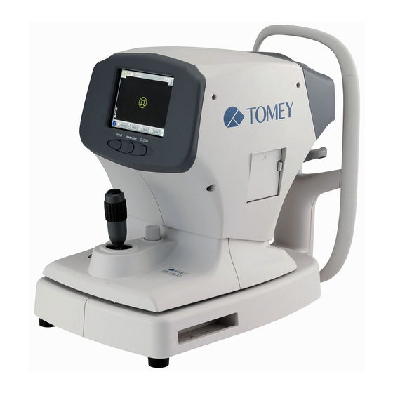
INSTRUCTION MANUAL
AUTO REFKERATOMETER
Read this manual thoroughly before using the
instrument to ensure proper and safe operation.
Contact Tomey Corporation or our local distributor
if you have any questions or you encounter any
problems during operation.
RC-800
Always follow the operation procedures
described in this manual.
Keep this manual in a readily
accessible location while operating the
instrument.
Contact our local distributor if you lose
this manual.
288A9090-00
Advertisement
Table of Contents

Related Manuals for Tomey RC-800


Summary of Contents for Tomey RC-800
- Page 1 AUTO REFKERATOMETER RC-800 Read this manual thoroughly before using the instrument to ensure proper and safe operation. Contact Tomey Corporation or our local distributor if you have any questions or you encounter any problems during operation. Always follow the operation procedures described in this manual.
- Page 3 To our customers This is a medical instrument used to measure the objective refraction and radius of corneal curvature. Although PD measurement, corneal diameter/pupil diameter measurement, and CL base curve diameter measurement features are loaded as optional functions, the validity of those measurements is not guaranteed.
- Page 4 This page is intentionally left blank.
- Page 5 Inappropriate wiring may damage the internal circuit. Never touch any of these terminals and the patient at the same time. Be sure to contact Tomey or our local distributor before using the external output terminal. When operating this instrument connected to other devices, only use...
- Page 6 Never mark or damage the caution labels on the instrument. Caution labels are provided on the side and at the bottom of the main unit (1 in each location). Contact Tomey or our local distributor when a label is damaged or becomes illegible.
-
Page 7: How To Read This Manual
ii How to read this manual Outline This manual is structured as follows. PRIOR TO USE Describes safety precautions important information to be understood before installing and using the instrument. NAMES AND FUNCTIONS Describes names and functions of each section of the instrument. -
Page 8: Symbols Used In This Manual
SYMBOLS USED IN THIS MANUAL Sentences accompanied with the symbols below indicate the following: This is a precaution that, if unheeded, will result in a hazardous situation where there is an imminent danger of serious injury or death. This is a precaution that, if unheeded, could result in a hazardous situation where there is a possibility of serious injury or death. -
Page 9: Table Of Contents
iii Contents Important Safety Information ..................i-1 How to read this manual ..................... ii-1 Outline ..........................ii-1 SYMBOLS USED IN THIS MANUAL ................ii-2 Contents ........................iii-1 PRIOR TO USE ......................1-1 1.1 Precautions for operation ..................1-1 1.2 Checking package contents ..................1-6 1.3 Glossary ........................ - Page 10 3.4.1 Printing procedures ..................3-21 3.4.2 Printing format ....................3-22 3.5 Showing and deleting data in memory ..............3-26 3.6 Data communication using TOMEY Link and DATA Transfer ......... 3-27 3.6.1 Entering patient information ................3-28 3.6.2 Sending examination data ................3-31 3.6.3 All clear of measurement data (preparation for measuring a new patient) ..
- Page 11 8.1.1 Refractive power measurement ................. 8-1 8.1.2 Corneal curvature measurement ............... 8-1 8.1.3 Pupillary distance measurement ................ 8-2 8.1.4 Corneal diameter and pupillary diameter measurement ........8-2 8.1.5 Observation range ..................... 8-2 8.1.6 Main unit ......................8-2 8.1.7 Power source ..................... 8-2 8.2 Environmental conditions ..................
- Page 12 This page is intentionally left blank. iii-4...
-
Page 13: Prior To Use
Conduct grounding work correctly. Otherwise you may get an electric shock. Do not connect a device with data transmission specifications that are not compatible. Fire or electric shock may occur. Contact Tomey... - Page 14 Corporation or our local distributor before using the instrument while connected to another device. Install the instrument in a location not subject to direct sunlight, high temperature and humidity, or air containing dust, salt, and/or sulfur. Otherwise, failure or malfunction may occur. Install the instrument in a leveled stable location free of vibration or mechanical impact.
- Page 15 There is a significant difference between the radii of corneal curvature of the left eye and the right eye. The degree of the calculated intraocular lenses is one that is less frequently used, or is out of the normal range. Note that if diopter is used as the measurement unit for the radius of corneal curvature, the measured value may differ depending on the cornea equivalent refractive index.
- Page 16 If any smoke, offensive odor, or abnormal sound occurs, turn off the instrument immediately, disconnect the power plug from the outlet, and contact our local distributor or Tomey Corporation. Precautions after operation Do not place any container with liquid in it on the instrument. Any liquid entering the instrument may cause electric shock or failure.
- Page 17 Otherwise, you may get an electric shock, resulting in death or serious injuries. Use the power cord and fuses provided with the instrument or specified by Tomey to ensure safety. Also, do not use the accessories provided with the instrument for other equipment. Conduct regular inspections of the instrument.
-
Page 18: Checking Package Contents
The instrument may be damaged. Main unit AUTO REFKERATOMETER RC-800 ..1 Power cord ..............1 Model eye ..............1 Fuse (2 fuses are installed in the main unit) ....4 Chin rest paper ............ -
Page 19: Glossary
: Shows the corneal diameter in the [DIA] mode for corneal diameter measurement/pupil diameter measurement. [DATA Transfer] : System to output the examination data created by TOMEY products as a file [IOL mode] : The mode used for eyes wearing IOL during refractometer... - Page 20 [TOMEY Link] : Digital medical record system to control the data measured with Tomey products [VD] : Vertex distance [mm] Represents the distance between the corneal vertex and the posterior surface of the lenses to be prescribed. When (VD=CL), vertex distance is calculated as 0 mm.
-
Page 21: Overview
1.4 Overview This is an objective refractive power measuring instrument used for measuring the spherical refractive degree, cylindrical refractive degree, and astigmatism axial angle of the patient's eyes. An ophthalmometer function for measuring the radius of corneal curvature is also provided. - Page 22 This page is intentionally left blank. 1-10...
-
Page 23: Names And Functions
2. NAMES AND FUNCTIONS 2.1 Physician's side (9) (10) (11) (12) (1) Measuring head (13) (14) (15) (16) Conducts measurement (2) Monitor / touch panel Displays the measurement screen and various setting screens. Touch the touch panel buttons shown on the LCD to make various settings and operate the instrument (see “2.3 Measurement screen”). - Page 24 (8) PRINT button Manually prints the measurement results. (9) TOMEY Link button Connects to TOMEY Link or other instruments. (10) CLEAR button Deletes the measurements. (11) Power lamp Stays lit when the instrument is turned on. (12) Chin rest button Pressing the UP “...
-
Page 25: Patient's Side
2.2 Patient's side (4) (5) (1) Measurement window The window from which the patient looks at the fixation target (2) Forehead pad (attachment section) The patient presses their forehead against this pad. (3) Chin rest (attachment section) The patient places their chin on this rest. (4) Power connector Connects a power cord. -
Page 26: Measurement Screen
2.3 Measurement screen (18) (13) (14) (17) (15) (16) (10) (11) (12) (1) Measurement mode display “RK”/”REF”/”KRT”/”DIA”/”CL” Measurement mode (Refkeratometer measurement “RK”/Refractometer measurement “REF”/Keratometer measurement “KRT”/Corneal diameter, pupil diameter measurement “DIA”/ Contact lens base curve measurement “CL”) is displayed. (2) Eye display button [R]/[L] Displays which side (left or right eye) the head is placed on in colors. - Page 27 (6) “Mode” button Switches the measurement mode. (7) “Temp” (temporary setting) button Sets the temporary measurement conditions only for one examination. (8) “Data” button Recalls the data saved in the memory. (9) Refractometer measurement value Current refractometer measurement value is displayed. S: Spherical refractive power C: Cylindrical refractive power A: Astigmatism axial angle...
-
Page 28: Operation Of The Joystick
(16) Auto Shot mark Displayed when Auto Shot is ON. (17) Focus indicator Displays the distance between the measuring head and the patient's eye. If there is a bar on the sides, move the head toward the patient. If there are bars above and below, move the head toward you and adjust the focus. -
Page 29: Symbols
2.5 Symbols Refer to instruction manual. Caution Power ON Power OFF Type B applied part Protective earthing Dangerous voltage... - Page 30 This page is intentionally left blank.
-
Page 31: Operation Procedures
3. OPERATION PROCEDURES 3.1 Safety precautions 3.1.1 Precautions for installing the instrument Install the instrument in a location free of water or chemicals. Any water or chemicals entering the instrument may cause an electric shock or failure. Do not install the instrument in a location where chemicals are stored or gases may occur. -
Page 32: Precautions For Connecting The Power Cord
3.1.2 Precautions for connecting the power cord Check that the frequency, voltage, and allowable current (or power consumption) of the power source are appropriate. Otherwise, fire or electric shock may occur. Connect the power plug to a grounded 3-pin outlet. Otherwise, a short circuit due to failure of the instrument may result in electric shock. -
Page 33: Checking The Printer Paper
3.1.5 Connecting optional components An external ID input device, personal computer, and TOMEY Link LAN adapter can be connected to the main unit using connectors. When TOMEY Link is used, measurement data can be output to a personal computer. - Page 34 Turn off the power switch of the instrument before changing connected devices. Otherwise, failure or malfunction may occur. <Connection to USB connector> (Fig.1) Check that the connector selection switch (1) located at the bottom on the right side when viewed from the physician’s side of the main unit is set to the left.
-
Page 35: Preparation Before Use
3.2 Preparation before use 3.2.1 Startup When restarting the instrument, turn the power off, wait for ten seconds or so, and turn it on again. Turn on the power switch (1). The power lamp lights and the measurement screen appears. When the power is turned on, the instrument starts in the (Fig.1) measurement mode selected when the power was last... -
Page 36: Selecting The Mode And Setting Measurement Conditions
3.2.2 Selecting the mode and setting measurement conditions The mode can be selected using the “Mode” button (1) on the touch panel. Touch the “Mode” button (1) to display the Mode Select screen (Fig. 2). Use the setting button (3) to select a mode. Touching the “Exit”... -
Page 37: Adjusting Patient Position
3.2.3 Adjusting patient position Be sure to press the CLEAR button on the right side under the LCD to delete the measurement data of the previous patient before starting measurement patient. measurement is started without deleting the previous data, the measurement data for the previous patient may be included. -
Page 38: Auto Shot
3.2.4 Auto Shot When moving the measuring head and/or chin rest of the instrument, pay attention to the position of the patient's face, hands, and fingers. The patient may be injured by the moving section of the instrument. Do not allow any person to place their hands or fingers in the clearance of the moving section of the main unit or the section immediately under the chin rest. - Page 39 Auto Shot function automatically performs measurement when the sight in the up/down/right/left /focus directions becomes optimum. If the Auto Shot function is turned on, the background of the letters [AS] on the lower right of the screen turns blue. Operate the joystick so the center-point (1) located in (Fig.1) the center of the cornea enters the target ring (2).
-
Page 40: Measurement
3.3 Measurement patient stop blinking during measurement. Auto Shot may not be able to make a measurement if the eyes are blinking too much, or if there are anomalies on the surface of the cornea, such as corneal disorders. In this case, perform a manual measurement. - Page 41 <Measurement procedures> 1) Change the measurement mode to “REF.” (See “3.2.2 Selecting the mode and setting measurement conditions.”) 2) Use the joystick to position the patient's eye on the screen. 3) Allow the target center-point to enter the target ring. When Auto Shot is ON, measurement starts automatically once optimum focus is achieved, and the specified number of measurements (three or five)
- Page 42 alignment is not performed; manual measurement, therefore, should only be performed when the patient's sight is too unstable. Eyelids and eyelashes are covering the minimum pupil size ring. Ask the patient to open their eyes wide or have the physician lightly hold the patient's upper eyelid with their fingers, and conduct measurement again.
-
Page 43: Measuring The Radius Of Corneal Curvature (Keratometry)
Optical accommodation is in progress The measurement may not be accurate when optical accommodation is in progress, such as immediately after removing corrective lenses, or just after performing tasks that require hard use of the eyes. Try again after a certain amount of time, or instruct the patient to look far away. - Page 44 <Measurement procedures> 1) Change the measurement mode to “KRT.” (See “3.2.2 Selecting the mode and setting measurement conditions.”) 2) Use the joystick to position the patient's eye on the screen. 3) Align the target center-point with the center of the target ring.
- Page 45 <When measurement is difficult> When measurement cannot be performed or an error is shown for the measurement result, the problems listed below have occurred. Conduct appropriate measures described below according to possible causes. Blinking or nystagmus Ask the patient to look into the lamp to steady their eye and start the measurement again.
-
Page 46: Measuring The Eye Refractive Power And Radius Of Corneal Curvature (Refkeratometer Measurement)
3.3.3 Measuring the eye refractive power and radius of corneal curvature (refkeratometer measurement) <Refkeratometer measurement screen> On the lower left of the monitor is the refractometer measurement value (1), and on the lower right is the keratometer measurement value (2). For details of refractometer measurement, see “3.3.1 Eye refractive power (refractometer) measurement mode,”... - Page 47 When specified number keratometric measurement values could not be obtained, the screen displays “KRT?” Touch the “Setup” button shown at the bottom screen without changing measurement mode, turn ON “Auto Shot” (4) on the Common Setup 1 screen, and perform measurement again.
-
Page 48: Corneal Diameter And Pupil Diameter Measurement
3.3.4 Corneal diameter and pupil diameter measurement This function enables you to acquire the image on the anterior eye segment, align the cursor to the pupil or to both sides of the cornea, and measure the distance between cursors to figure out the size of the pupil and cornea. - Page 49 5) Touch the cursor selection button (6) to switch the active cursor. 6) The distance between the cursors measuring the corneal diameter is shown in CORNEA (7), and the distance between the cursors measuring the pupil diameter is shown in PUPIL (8). 7) Touch the “OK”...
-
Page 50: Contact Lens Measurement
3.3.5 Contact lens measurement The function used when measuring the base curve of hard contact lenses. Make sure that the concave side of the contact lens holder does not have air bubbles. Be careful not to wet or stain the measurement surface. -
Page 51: Printout
3.4 Printout 3.4.1 Printing procedures Check that the paper roll is set in the built-in printer. (See “5.5.1 Printer paper.”) When Print for the built-in printer is turned off on the Output Setup screen, printing cannot be performed. Refer to “3.8.1 Setup” to turn on the Print setting for the built-in printer. -
Page 52: Printing Format
3.4.2 Printing format Contents to be printed can be selected. Set the Print Form settings on the Output Setup screen. See “3.8.1 Setup.” Printing item (* indicates initial setting upon delivery.) Item Descriptions Prints measurement values for right eye and left Enable * Left/right eye separately. - Page 53 All * Prints all the data in the memory. Representati Prints only the representative value. ve value Average Prints only the average value. Keratometer data value Representati Prints the representative value with an asterisk (*). ve value + AVG Prints the measured value and average value. Normal * Prints K1K2, AVG, CYL/AXIS.
- Page 54 <Example printout A> Printing all items (1) Patient's name field (2) ID (3) Measurement date and time (4) Exam No. (5) Measuring eye (6) Refractometer display (10) (7) Vertex distance (11) (8) Refractometer measurement value (9) Representative value (10) Confidence coefficient (12) (13) Displayed in 10 steps, from 0 to 9.
- Page 55 <Example printout B> When the following items are selected Left/right separation -> Disabled Refractometer data -> +Representative value Keratometer data -> +Representative value Keratometer data format -> K1K2 Residual astigmatism -> Disabled (1) Physician's name field (2) ID (3) Measurement date and time (4) Exam No.
-
Page 56: Showing And Deleting Data In Memory
3.5 Showing and deleting data in memory This function is used to recall various measurement values stored in the memory. Press the CLEAR button to delete all data stored in the memory. When the next measurement is conducted after printing the measurement data, the printed data is deleted from the memory. -
Page 57: Data Communication Using Tomey Link And Data Transfer
In addition, the patient ID can be entered via magnetic cards or barcodes when a card reader or barcode reader is connected to the LAN adapter (optional) or personal computer (for TOMEY Link) or to the personal computer (for DATA Transfer). -
Page 58: Entering Patient Information
When the data is sent to TOMEY Link without entering an ID number, TOMEY Link recognizes that all the received data belongs to the same 3-29 (Fig. - Page 59 (Fig. 2) displays the patient data input screen (Fig. 3). Patient’s Information 2) ID numbers entered by TOMEY Link or DATA Transfer can be loaded to the instrument on the Patient’s Info screen. 3) Touching the field of the item to be entered displays the keypad shown in Fig.
- Page 60 6) Touch the “OK” button (5) to define the entered patient information and return to the measurement screen. Touching the “Cancel” button (6) cancels what has been entered and returns you to the measurement screen. 3-30...
-
Page 61: Sending Examination Data
When the data is sent to TOMEY Link without entering an ID number, TOMEY Link recognizes that all the received data belongs to the same patient. - Page 62 sent, the message “Sending completed” appears and the previous screen appears. 4) When it is found that incorrect patient information was entered before sending the data, touch the “Cancel” button (4) to return to the measurement screen without validating change(s) to the patient information. 3-32...
-
Page 63: All Clear Of Measurement Data (Preparation For Measuring A New Patient)
3.6.3 All clear of measurement data (preparation for measuring a new patient) The deleted data cannot be restored. Carefully check the data before deleting it. Press the CLEAR button (1) under the touch panel (Fig. 1). The patient information (ID, number, name, and sex) and measured data are all deleted, the inspection number increases by 1, and the new measurement screen appears. -
Page 64: Data Communication Using Tomey Form
3.7 Data communication using TOMEY FORM TOMEY Form, one of the COM options, allows you to send the measurement data via RS-232C under the communication settings shown in Fig. 1. Touching the ID number display field (1) on the measurement screen (Fig. 2) displays the keypad shown in Fig. -
Page 65: Setting Measurement Conditions
3.8 Setting measurement conditions 3.8.1 Setup Set operation conditions on this screen. Any settings made here are effective unless directly changed. After changing the settings, be sure to touch the “Save & Exit” button to exit the screen. If the “Cancel”... - Page 66 a) Common 1 Items commonly applicable to various measurements are set on this screen. Auto Power Off 5 minutes: Enters Auto Power Off mode when the instrument is not operated for 5 minutes. 10 minutes: Enters Auto Power Off mode when the instrument is not operated for 10 minutes.
- Page 67 b) Common 2 Items commonly applicable to various measurements are set on this screen. Time Adjust Adj.: Sets the date and time. Touch the “Adj.” button (1) to display the Time Adjust screen (Fig. 2). The setting in each field (2) can be changed when touched.
- Page 68 c) REF Setup Sets the measurement conditions. Measurement time 3: Conducts measurement three times continuously when Auto Shot is ON. 5: Conducts measurement five times continuously when Auto Shot is ON. High Speed (high speed measurement) (Fig. 1) 3-36 Enables High-speed mode. OFF: Disables High-speed mode.
- Page 69 d) KRT Setup Sets the keratometer measurement conditions. Measurement time 1: Conducts measurement once when Auto Shot is 3: Conducts measurement three times continuously when Auto Shot is ON. Unit (Fig. 1) 3-38 D: Displays the keratometer value in diopters. Diopter Step Sets the display units for the measurement value of corneal refractive power.
- Page 70 (Fig. 3) Sets the format for external communication. Touch the “Select” button (5) to display the COM selection screen (Fig. 4). TOMEY Link: Connects to TOMEY Link / DATA Transfer to send/receive data. Phoropter: Connects to Ref Tester to transmit data.
- Page 71 It is recommended to enter the ID number to correctly match the measurement data with the patient. Touch the “TOMEY Link” button in the COM options to display the setup screen (Fig. 5). Touch the exit button (7) to return to the Output Setup screen (Fig. 1).
- Page 72 ID for measuring data with this instrument and for printing or sending the measured data, regardless of connection with TOMEY Link. ID Input: The priority is given to entry of the ID. The Patient’s Info screen appears when the...
-
Page 73: Temporary Setup
3.8.2 Temporary setup CL are used for reference when selecting trial lenses, before prescribing contact lenses. Prescription contact lenses should determined after performing fitting exams. Temporary disabling of Auto Fogging should only be used when adjustment intervention can be ignored. In all other cases, adjustment intervention is likely to be carried out during refractometer measurement. - Page 74 Auto Fogging Auto Fogging, applied alleviate adjustment intervention during refractometer measurement, can be disabled temporarily. Refraction measurement may not be carried out easily if the patient's eyes are moving frequently due to nystagmus or unstable sight. Should that be the case, disable the Auto Fogging temporarily to shorten the time required for refractometer measurement.
-
Page 75: Language Selection
3.9 Language selection RC-800 has Multilanguage function. You can select your favorite one from “English”, “Japanese”, “German”, “Chinese”, “Spanish”, “Spanish Latin America”, “Italian”, “Portuguese”, “French” and “Russian”. Press the Setup button (1) in the Touch Panel to change the screen to the Setup screen. Next, press the icon located in left bottom (2) to go Information screen. - Page 76 This page is intentionally left blank. 3-46...
-
Page 77: Technical Information
4. TECHNICAL INFORMATION Cornea equivalent refractive index used to calculate corneal refractive power Although corneal refractive index is originally n=1.376, this instrument uses the corneal conversion refractive index of n=1.3375, which is used in many keratometers. The total refractive index of the cornea is determined by the sum of the refractive powers of the front and rear sides. - Page 78 This page is intentionally left blank.
-
Page 79: Inspection And Maintenance
This warranty also shall NOT apply if the product has not been installed, operated or maintained in accordance with the INSTRUCTION MANUAL of Tomey Corporation (here in after called “Tomey” ). Neither seller nor Tomey shall be liable for any damages caused by purchaser's failure tofollow instruction for proper installation, use and maintenance of product. -
Page 80: Operation Life
5.2 Operation life This instrument is designed to have an operation life of 8 years when operated under the appropriate environment and adequately inspected and serviced. 5.3 Inspection When measuring the imitation eyes, check that there is no dust or stain on them. To make sure that the internal functions operate correctly and performance is maintained, use the imitation eyes to check the accuracy before using the instrument. -
Page 81: Routine Maintenance
5.4 Routine maintenance Hold the plug when disconnecting the power cord from the outlet to avoid placing excessive force on the cord. Pulling the cord may damage the inner core wires, resulting in electric shock or fire. Do not use organic solvents such as thinner, benzene, or acetone to clean the instrument. -
Page 82: Replacing Consumables
5.5 Replacing consumables 5.5.1 Printer paper Never touch the cutter in the printer. Also, never allow patients to touch the cutter. Touching this can cause injuries. Use the specified paper for the printer. Using other types of paper may cause printer failure. Do not start printing without paper set in the printer. -
Page 83: Fuses
Otherwise, you may get an electric shock, resulting in death or serious injuries. Use fuses specifically designed for the RC-800. When the instrument does not work correctly after fuses have been replaced, there may be other causes of the problem. Turn off the instrument immediately and contact our local distributor. -
Page 84: Chin Rest Paper
5.5.3 Chin rest paper Remove the two chin rest paper pins. Place new chin rest paper on the chin rest and secure the paper with the paper pins. (Fig.1) -
Page 85: Storing
5.6 Storing Install the instrument in a location free of water or chemicals. Any water or chemicals entering the instrument may cause an electric shock or failure. Do not store the instrument in a location where chemicals are stored or gases may occur. Spilt chemicals or vapor may enter the instrument and result in fire. -
Page 86: Disposal
5.7 Disposal Keep the box and packing materials for use when moving or transporting the instrument. Keep the packing materials and the box together. When disposing of the packing materials, sort them by type and dispose of them as directed by relevant laws and local rules and regulations. -
Page 87: Troubleshooting
6. TROUBLESHOOTING Check the following first when you encounter any problems. If the problem is not solved even after checking the applicable item listed below, contact our local distributor. Do not remove the cover of the instrument. You may be directly exposed to high voltage sections. - Page 88 Blown fuse Check that fuses are not blown. If blown, replace the fuse (refer to “5.3.2 Fuses”). When the new fuse is blown again, the instrument may be out of order. Contact local distributor request inspection and/or repair. The monitor is dark when the power switch is turned on. The auto power off function, which automatically turns off the screen when the instrument is not operated for the specified...
- Page 89 The error message “Printer error” is displayed. There is a problem with the printer. Contact our local distributor. Stable measurement results are not obtained. The measured value is inappropriate or greatly deviates from the previous value. The measurement window is dirty. Check that the measurement window is clean.
- Page 90 The error message “Refractometer error” is displayed. There are problems with the refractometer functions of the instrument. Contact our local distributor. The error message “Keratometer error” is displayed. There are problems with the keratometer functions of the instrument. Contact our local distributor. The error message “Chin rest error”...
-
Page 91: Consumables
The following consumable parts are available from our local distributor. Contact our local distributor to order them. Built-in printer paper Specify the paper type as “Built-in printer paper for RC-800.” Chin rest paper (100 sheets/set) Fuse Specify the fuse type as “Fuse for RC-800.”... - Page 92 This page is intentionally left blank.
-
Page 93: Specifications
8. SPECIFICATIONS 8.1 Specifications 8.1.1 Refractive power measurement Spherical refractive power (S) Measurement range: -25.00D to +22.00D (at VD=12.0mm) Display unit: 0.01D / 0.12D / 0.25D Cylindrical refractive power (C) Measurement range: 0D to ±10.00D (at VD=12.0mm) Display unit: 0.01D / 0.12D / 0.25D Astigmatism axial angle (A) Measurement range: 0°... -
Page 94: Pupillary Distance Measurement
8.1.3 Pupillary distance measurement Measurement range: 50 to 86mm Display unit: 8.1.4 Corneal diameter and pupillary diameter measurement Corneal diameter measurement Measurement range: 10.0 to 14.0mm Display unit: 0.1mm Pupillary diameter measurement Measurement range: 1.0 to 10.0mm Display unit: 0.1mm 8.1.5 Observation range Approx. -
Page 95: Environmental Conditions
8.2 Environmental conditions This instrument shall be used in the following environmental conditions. Installing place: indoors where the instrument is free from direct sunbeams. Temperature: +10 to +40°C Humidity: 30 to 75 % Atmospheric pressure: 800 to 1060 hPa Power modulation: Less than ±10% of nominal voltage Store and transport this instrument in the instrument's box under the following environmental conditions. -
Page 96: Declaration Of Conformity To Emc
Table 201 The RC-800 is intended for use in the electromagnetic environment specified below. The customer or the user of the RC-800 should assure that it is used in such an environment. Emissions test Compliance Electromagnetic environment - guidance... - Page 97 Table 202 The RC-800 is intended for use in the electromagnetic environment specified below. The customer or the user of the RC-800 should assure that it is used in such an environment. Immunity test IEC 60601 test Compliance level...
- Page 98 Guidance and manufacturer's declaration electromagnetic immunity Table 204 The RC-800 is intended for use in the electromagnetic environment specified below. The customer or the user of the RC-800 should assure that it is used in such an environment. IEC 60601 test Compliance Immunity test...
- Page 99 RC-800 Table 206 The RC-800 is intended for use in an electromagnetic environment in which radiated RF disturbances are controlled. The customer or the user of the RC-800 can help prevent electromagnetic interference by maintaining a minimum distance between portable and mobile RF communications equipment (transmitters) and the RC-800 as recommended below, according to the maximum output power of the communications equipment.
- Page 100 This page is intentionally left blank.
-
Page 101: Index
9. INDEX Eye display button .......... 2-4 Eye level mark ......... 2-1, 3-7 A ..............1-7 Adjustment ..........1-8, 3-43 Astigmatism axial ....1-7, 1-9, 2-5, 3-10, Focus indicator ........2-6, 3-9 3-38, 3-39, 8-1 Auto ............... 1-7 Auto Fogging ....... 1-8, 3-43, 3-44 High Speed ........... - Page 102 Temporary ............1-7 Radius of corneal curvature ....1-7, 1-9, Temporary setup .......... 3-43 3-13, 3-16, 3-17, 4-1 TOMEY Link .......... 1-8, 3-41 REF ............... 3-6 Touch panel ..........1-8, 2-1 Refractive power ....1-7, 2-5, 3-10, 3-16, 3-17, 3-38, 3-39, 4-1, 8-1 Reliability ..........
- Page 103 Fax: +81 52-561-4735 EC-Representative Tomey GmbH Am Weichselgarten 19a 91058 Erlangen GERMANY Tel: +49 9131-77710 Fax: +49 9131-777120 AUTHORIZED TOMEY SERVICE CENTERS Headquarters, Pacific Rim Tomey Corporation 2-11-33 Noritakeshinmachi Nishi-ku, Nagoya 451-0051 JAPAN Tel: +81 52-581-5327 Fax: +81 52-561-4735 Europe...
Need help?
Do you have a question about the RC-800 and is the answer not in the manual?
Questions and answers