Table of Contents
Advertisement
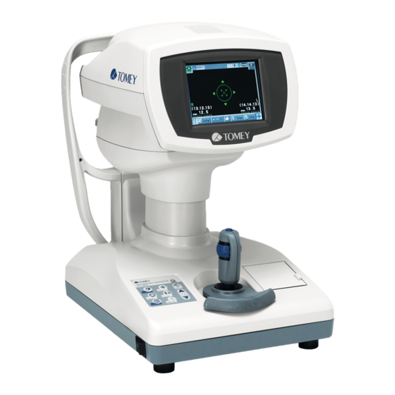
INSTRUCTION MANUAL
NON-CONTACT TONOMETER
Carefully read this instruction manual before
using this instrument to ensure correct and safe
operation.
If you have questions about operations, please
contact Tomey Corporation or our local distributor.
Always follow the operation procedures
described in this manual.
Keep this manual in a readily available
location while operating the instrument.
Contact our local distributor if you lose
this instruction manual.
FT-1000
401A9090-3
Advertisement
Table of Contents

Related Manuals for Tomey ViewLight FT-1000


Summary of Contents for Tomey ViewLight FT-1000
- Page 1 Carefully read this instruction manual before using this instrument to ensure correct and safe operation. If you have questions about operations, please contact Tomey Corporation or our local distributor. Always follow the operation procedures described in this manual. Keep this manual in a readily available location while operating the instrument.
- Page 3 i Important Safety Information Do not install this instrument in a location where explosives or inflammable substances are used or stored. Otherwise, fire or explosion may occur. Do not remove the cover of the instrument. You may be directly exposed to high voltage sections. Do not disassemble or modify the instrument.
- Page 4 Never damage or cause caution marks provided for the instrument to become illegible. Caution labels are provided on the sides, bottom, and physician's side of the instrument. If a label is damaged or becomes illegible, please contact Tomey Corporation or our local distributor. Caution label...
-
Page 5: How To Read This Manual
ii How to Read This Manual Outline This manual is structured as follows. 1. PRIOR TO USE Describes safety precautions and important information to be understood before installing and using the instrument. 2. N A M E S A N D F U N C T I O N S O F PA R T S A N D COMPONENTS Describes names and functions of each section of the instrument. -
Page 6: Symbols Used In This Manual
SYMBOLS USED IN THIS MANUAL The symbols below indicate the following: This is a precaution that, if unheeded, will result in a hazardous situation where there is an imminent danger of serious injury or death. This is a precaution that, if unheeded, could result in a hazardous situation where there is a possibility of serious injury or death. -
Page 7: Table Of Contents
iii Contents I Important Safety Information ..................ii How to Read This Manual .................... ii-1 Configuration ......................ii-1 SYMBOLS USED IN THIS MANUAL ..............ii-2 iii Contents ........................iii-1 1. PRIOR TO USE ......................1.1 Precautions for operation .................. 1.2 Checking of shipments ..................1.3 Glossary ...................... - Page 8 3.6.2 Receiving the patient data ................ 3-21 3.6.3 Sending the examination data ..............3-22 3.7 Settings ......................3-24 3.7.1 Initial setup (Setup) ................... 3-24 3.7.2 Temporary setup (Temporary) ..............3-30 4. TECHNICAL INFORMATION ..................4.1 Adjusting intraocular pressure according to cornea thickness ......4.2 Performance test result for the device ..............
-
Page 9: Prior To Use
1. PRIOR TO USE Read this manual thoroughly before using the instrument to ensure proper and safe operation. Always follow the operation procedures described in this manual. Check that there is no device that generates strong magnetic field near the instrument. The strong magnetic field may cause noise and affect measurement. - Page 10 When connecting a device to the instrument using the RS-232C connector, contact Tomey Corporation or our local distributor. – Ground the instrument appropriately. Otherwise you may get an electric shock. – Do not hold the measuring head, chin rest, forehead pad, or joystick when lifting the instrument.
- Page 11 – When moving the measuring head and/or chin rest of the instrument, pay attention to the position of the patient's face, hands, and fingers. The patient may be injured by the moving section of the instrument. – When supporting the patient’s face with a hand, pay the utmost attention to the position of the hand or fingers and carefully operate the instrument.
- Page 12 – Use the power cord and fuses provided with the instrument or specified by Tomey to ensure safety. Also, do not use the accessories provided with the instrument for other equipment.
- Page 13 1.2 Checking contents of package Open the package and check that the specified amount of the following items are included in the package and are not damaged. If any item is missing or damaged, contact our local distributor as soon as possible. ...
-
Page 14: Glossary
[TOMEY Link]: Digital medical record system to control the data measured with Tomey products [DATA Transfer]: System to output the measurement data from Tomey products to digital files [Auto Measurement mode]: Mode to automatically conduct alignment and measurement [Auto Shot]:... -
Page 15: Outline Of Operation
1.4 Outline of operation This instrument is designed to calculate the intraocular pressure. For more details regarding accuracy, precision, and clinical comparison of the IOP measurements to the Goldmann applanation tonometer please refer to Section 4.3 of the Instruction Manual. FT-1000 is an instrument used to measure the intraocular pressure of a patient's eye. - Page 16 This page is intentionally left blank. 1 -8...
-
Page 17: Names And Functions Of Parts And Components
2. NAMES AND FUNCTIONS OF PARTS AND COMPONENTS 2.1 Physician's side (14) (19) (17) (11) (15) (12) (18) (4) (5) (13) (16) (1) Measuring head (10) Section that conducts measurement. (2) Monitor / touch panel Displays the measurement screen and various setting screens. Touch the touch panel buttons shown on the LCD to make various settings and operate the instrument. - Page 18 Determines the stop position of the measuring head to prevent the nozzle from contacting the patient's eye. (16) "TOMEY Link" button Sends the measurement data to TOMEY Link or DATA Transfer. (17) "PACKING" button Pressing this button for 3 seconds moves the measuring head to the lowest position for packing (lower dead center).
-
Page 19: Patient's Side
2.2 Patient's side (1) Measurement window Blows air onto the patient's eye from the center nozzle. (2) Chin rest The patient places their chin on this rest. (3) Forehead pad The patient presses their forehead against this pad. (4) Power switch Press the [I] or [O] side to turn the instrument on or off respectively. -
Page 20: Measurement Screen
2.3 Measurement screen (4) (5) (6) (7) (27) (28) (21) (24) (23) (25) (22) (17) (17) (18) (18) (26) (19) (19) (20) (20) (15) (12) (28) (13) (14) (16) (9)(10) (11) (1) Eye display button [R]/[L] Displays the right or left eye on which the measuring head is positioned, using the corresponding color. - Page 21 (6) High intraocular pressure measurement mode [High] This mark appears when the instrument is in High Intraocular Pressure Measurement mode. The pressure can be measured up to 30 mmHg in Normal mode and from 25 - 60 mmHg in this mode. (7) Limiter This mark is shown in light blue when the limiter is activated;...
- Page 22 (20) Stored data The dot corresponding to the number of the stored data turns green, yellow, or red according to reliability. "Green" is regarded as the most reliable and "red" as the least reliable. (21) Target center-point Indicates the position of the cornea vertex. (22) Target ring Index reference used when aligning the patient's eye position for measurement.
-
Page 23: Operation Of The Joystick
2.4 Operation of the joystick There are two types of operations - rough operation for moving the measuring head into rough position and fine operation for finely adjusting the position of the measuring head. The measurement button is located on the top of the joystick. <Rough operation>... -
Page 24: Touch Alignment
2.5 Touch Alignment Touch Alignment is a function for alignment using the touch panel. Touch Alignment needs to be enabled before it can be used (refer to "3.7.1 Initial setup"). This is available in all measurement modes. Touch Alignment is used for rough positioning. Use the joystick for fine positioning. -
Page 25: Rs-232C Connector
Refer to the corresponding instruction manual for installation, settings, and operation of TOMEY Link and DATA Transfer. Special settings are required to communicate with TOMEY Link and DATA Transfer. Refer to "3.7.1 d) Output Setup" and make appropriate settings. 2- 9... - Page 26 The RS-232C connector is a terminal used to export measurement data to an external device. When connecting a computer running TOMEY Link or DATA Transfer, use the following cable and adapter. Connection cable: RS-232C cable (D-Sub 9 pin: Interlink or cross)
-
Page 27: Symbols Used For Marking
2.7 Symbols used for marking Refer to instruction manual. Caution “ON” (power) “OFF” (power) Type B applied part Grounding (earth) Dangerous voltage 2-11... - Page 28 This page is intentionally left blank. 2 -1 2...
-
Page 29: Operation Procedures
3. OPERATION PROCEDURES 3.1 Safety precautions 3.1.1 Precautions for installing the instrument Install the instrument in a location free of water or chemicals. Any water or chemicals entering the instrument may cause an electric shock or failure. Do not install the instrument in a place where chemicals are stored or gases may occur. -
Page 30: Precautions For Connecting The Power Cord
3.1.2 Precautions for connecting the power cord Connect the power plug to a grounded 3P-outlet. Otherwise, a short circuit due to failure of the instrument may result in an electric shock. Do not place any heavy object on the power cord or squash the power cord. -
Page 31: Preparation For Measurement
3.2 Preparation for measurement 3.2.1 Starting Immediately after starting the instrument, the measuring head moves and an air blow test is performed. Do not allow the patient to place their face on the chin rest until the air blow test is complete. Otherwise the patient may be injured. -
Page 32: Measurement
3.3 Measurement This instrument is designed to calculate the intraocular pressure. For more details regarding accuracy, precision, and clinical comparison of the IOP measurements to the Goldmann applanation tonometer please refer to Section 4.3 of the Instruction Manual. When the measured value is doubtful as described below, review the examination result by re- measurement with this instrument or using the Goldmann applanation tonometer. -
Page 33: Precautions
3.3.1 Precautions Do not use this instrument for eyes with weak corneas due to disease or surgery. Doing so may result in complications or damage to the cornea. What is the weak corneas? Example : Corneal ablation eye, corneal transplan- tation eye, Refraction correction eyes such as LASIK, Corneal transplantation eye, Vitreous body eye, Diffuse punctuate... -
Page 34: Nozzle Limiter Setting
1) Have the patient place their face on the chin rest (1). (3) (4) Adjust the chin rest height so that the height of the corner of the eye is aligned with eye level mark (2). – Touch the "CHIN REST UP" button (5) to raise the chin rest;... - Page 35 1) Check that the limiter mark (1) in the upper right of the screen indicates that the nozzle limiter is OFF. If ON, touch the "LIMITER" button to turn it OFF. ON: Light blue OFF: Flashing red 2) Touch the "AUTO" button (2) in the lower right of the (Fig.
-
Page 36: Alignment
3.3.4 Alignment When supporting the patient’s face with a hand, pay the utmost attention to the position of the hand or fingers and carefully operate the instrument. The hand or fingers may be caught between the head and forehead pad, resulting in injuries. ... - Page 37 2) Lightly touch the cornea center (1) on the screen. – The measuring head moves so the patient's eye is positioned in the center of the screen. When the target center-point (2) in the center of the cornea enters the alignment ring (3), focusing in the horizantial vertical directions automatically starts.
-
Page 38: Measuring Intraocular Pressure
1) Operate the joystick so the center of the cornea (1) enters the target ring (3). The target center-point (2) is displayed. 2) Move the joystick back and forth to move the measuring head so the focus indicator (4) on the screen becomes (Fig. - Page 39 A f t e r m e a s u r e m e n t i s c o m p l e t e , t h e n u m b e r o f measurements is incremented by one every time Auto Measurement is enabled by touching the "AUTO"...
- Page 40 The intraocular pressure data for 10 measurements per eye can be saved. When the number of measurements exceeds this limit, the oldest data will be deleted accordingly. <When measurement is difficult> When measurement cannot be conducted or an error occurs in the measurement result, check the following and take appropriate action.
-
Page 41: Popup Window For Selecting The Measurement Range
3.3.6 Popup window for selecting the measurement range <Measurement in Normal mode> When “OVER” is measured twice consecutively, the popup window for selecting the measurement range (Fig.1) appears. Select the measurement range. (Fig. 1) <Measurement in High IOP mode> When “UNDER” is measured twice consecutively, the popup window for selecting the measurement range (Fig.2) appears. -
Page 42: Printout
3.4 Printout 3.4.1 Printing procedure Check that the paper roll is set in the built-in printer (refer to "5.5.1 Printer paper"). When the next measurement is conducted after printing, the measured data is automatically deleted and the examination number increases by one. ... -
Page 43: Printing Format
3.4.2 Printing format The contents to be printed can be selected. Set the Print Form settings on the Output Setup screen. Refer to "3.7.1 Initial setup" for details. Printing item (* indicates initial settings upon delivery.) Item Descriptions Enable * Prints the date and time. - Page 44 14.2mmHg The reliability of the measurement is indicated (12) TOMEY Corp. FT‑1000 using three ranks: A, B, or C. "e" or "E" indicates unreliable data. In this case, the measured value is printed to the right of the reliability code.
-
Page 45: Viewing The Measurement Data
5) Touch the internal data printout button (7) to print the internal data useful for locating the cause of defective data. Report the details of the problem during measurement to our local distributor or Tomey Corporation using the printout of the internal data. 3-1 7... -
Page 46: Adjusting The Measurement Data
3.5.2 Adjusting the measurement data Adjust the measurement data stored in the memory according to the central corneal thickness (CCT). 1) Touch the central corneal thickness field (CCTR or CCTL) of the data to be adjusted (1). The keypad appears. Enter the measured central corneal thickness. 2) The intraocular pressure adjusted according to the central corneal thickness is shown in the "aIOP"... -
Page 47: Data Communication
In addition, all data sent to TOMEY Link without the ID is regarded as the information of one patient. Be extremely careful not to misidentify the data. - Page 48 1) When COM (external communication) on the Output Setup screen is ON, the Patient Information screen (Fig. 1) appears after the operations listed below. Enter the ID and/or patient's name as needed. • Immediately after starting the instrument • Immediately after touching the "CLEAR" button Cancel •...
- Page 49 ID via a barcode or electromagnetic card, connect the appropriate reading device to the computer with DATA Transfer installed. The patient data query function of TOMEY Link also allows you to display the entered ID and corresponding patient's name registered in TOMEY Link on the instrument.
- Page 50 In addition, all data sent to TOMEY Link without the ID is regarded as the information of one patient. Be extremely careful not to misidentify the data.
- Page 51 1) Touch the TOMEY Link button (1) after measurement to recall the Patient Information screen (Fig. 2). When Auto Print is ON, this screen appears automatically after printing is complete. Touching the "CLEAR" button (6) deletes the patient data and measurement data, and returns you to the Patient Information screen.
- Page 52 3.7 Settings 3.7.1 Initial setup (Setup) The operation conditions can be set here. Any settings made here are effective unless directly changed. After changing the settings, be sure to touch the "Save & Exit" button to exit the screen. If the "Cancel" button is touched, no changes are made to the settings and the conditions previously set are still effective.
- Page 53 a) Common 1 Set items related to operation conditions. (1) Auto Power Off Common1 5 min: E n t e r s A u t o P o w e r O ff m o d e w h e n t h e instrument is not operated for 5 minutes.
- Page 54 This instrument is equipped with an internal battery for the clock and backup. When the error message "Internal battery low" appears, contact your local distributor or Tomey Corporation. Do not attempt to replace the internal battery. If you need the correct time displayed but the battery has expired, set the time after turning on the instrument.
- Page 55 c) Tonometer Setup Set the measurement conditions. (1) Measurement Times Conducts measurement once when Auto Shot is ON. Conducts measurement three times continuously Tonometer when Auto Shot is ON. (2) Popup window for selecting the measurement range Enables the popup window for selecting the measurement range.
- Page 56 "3.4.2 Printing format" for details of each setting item. Touch the "Exit" button (8) to return to the previous screen (Fig. 1). (3) COM (Fig. 2) Enables communication with TOMEY Link or DATA Transfer to send or retrieve data. OFF: Disables communication with any external device.
- Page 57 e) Information Displays the product information. f ) Safety function Makes the settings for the safety functions. When the alarm for nearness is set to OFF, the physician may not notice that the nozzle moves too close to the patient and the nozzle makes contact with the patient, resulting in injuries.
- Page 58 3.7.2 Temporary setup (Temporary) Set conditions for a specific measurement only. The setting is canceled when the corresponding measurement is completed. Refer to "3.7.1 Initial setup" for settings for continuous operation conditions. Touch the "Temp" button. Set the following items and touch the "Exit" button (6). The changes are reflected in the settings and the screen returns to the measurement screen (Fig.
- Page 59 4. TECHNICAL INFORMATION 4.1 Adjusting intraocular pressure according to cornea thickness It is generally said that measurement of the intraocular pressure, typically by the Goldmann applanation tonometer, is largely affected by the cornea. The influence of the cornea can be adjusted to some extent by the measured central corneal thickness (CCT).
- Page 60 4.2 Performance test result for the device 4.2.1 Method The test was performed with three pressure-controlled model. The pressure was set every 10mmHg from the lower limit value to the upper limit in each model. (0,10,20,30, 40,50,60mmHg) The measurement was performed using the auto alignment function and the above- mentioned procedure was repeated 10 times in each model.
- Page 61 4.3 NON-CONTACT TONOMETER FT-1000 Clinical data (ISO8612:2001) The range from 0 - 60 mmHg was evaluated on the bench. Additionally, the range 7 mmHg - 34 mmHg was clinically evaluated against the Goldmann applanation tonometer Test method : Performed as described in ISO8612:2001 Annex A,B. Test period : 11 Mar.
- Page 62 This page is intentionally left blank. 4 -4...
- Page 63 INSPECTION MANUAL of Tomey Corporation (here in after called "Tomey"). Neither seller not Tomey shall be liable for any damages caused by purchaser's failure to follow instruction for proper installation, use and maintenance of product.
- Page 64 Otherwise the patient may be injured. If any problem occurs in the instrument, correct measurement may not be assured. Contact our local distributor or Tomey Corporation for necessary repairs as soon as possible. The instrument automatically performs an air blow test when started.
- Page 65 5.4 Routine maintenance Hold the plug when disconnecting the power cord from the outlet to avoid applying excessive force on the cord. Pulling the cord may damage inner core wires, resulting in electric shock or fire. Do not use organic solvents such as thinner, benzene, or acetone to clean the instrument.
- Page 66 5.4.2 Forehead pad Gently wipe the sections that patients directly touch, such as the forehead pad, with a soft cloth dampened with alcohol before starting measurement for a new patient. 5.4.3 Outer surface When the outer surface of the instrument becomes dirty, clean it with a dry, soft cloth.
- Page 67 5.5 Replacing consumables 5.5.1 Printer paper Do not touch, or allow patients to touch, the printer cutter. Touching the cutter may result in injuries. Use the specified paper for the printer. Using other types of paper may cause printer failure. ...
- Page 68 5.5.2 Fuses Disconnect the power cord from the outlet when replacing fuses. Otherwise you may get an electric shock, resulting in death or serious injuries. Use fuses specifically designed for the FT-1000. When the instrument does not work correctly after fuses are replaced, there may be other causes of the problem.
- Page 69 5.6 Storing Store the instrument in a location free of water or chemicals. Any water or chemicals entering the instrument may cause an electric shock or failure. Do not store the instrument in a place where chemicals are stored or gases may occur. Spilt chemicals or vapor may enter the instrument and ignite.
- Page 70 A lithium battery is used in the instrument. Handling of the lithium battery varies depending on governing bodies. Follow relevant laws and local rules and regulations, or contact our local distributor or Tomey Corporation. 5 -8...
- Page 71 6. Troubleshooting Check the following first when you find problems with the instrument. If the problem is not solved even after checking the applicable item listed below, contact our local distributor. Do not remove the cover of the instrument. Otherwise, you may be directly exposed to high voltage sections.
- Page 72 ● The monitor is dark when the power switch is turned Auto Power Off, which automatically turns off the display when the instrument is not operated for a specific time, is ON. Touch the LCD ● The data cannot be printed by the built-in printer. The printer has run out of paper.
- Page 73 ● The error message "Internal Error" is displayed. There are problems with the internal functions of the instrument. Stop using the instrument and contact our local distributor. ● The error message "Internal Battery Empty" is displayed. The internal battery has expired. Contact our local distributor and have the internal battery replaced.
- Page 74 Refer to the instruction manual of TOMEY Link and/or DATA Transfer for details. There may be an error in TOMEY Link and/or DATA Transfer. Check that there is no error in TOMEY Link or DATA Transfer (including the relay software).
- Page 75 7. Consumables Contact our local distributor to order any of the following consumables. ● Built-in printer paper Specify the paper type as "Built-in printer paper for FT-1000." ● Chin rest paper (100 sheets/set) ● Fuse Specify the fuse type as "Fuse for FT-1000." 7- 1...
- Page 76 This page is intentionally left blank. 7 -2...
- Page 77 8. Specifications 8.1 Specifications 8.1.1 Measuring IOP ● Measurement range : 0 - 60 mmHg (0 - 30 mmHg / 25 - 60 mmHg) ● Measurement : 1 mmHg (1 hPa) increments within the measurement range 8.1.2 Main unit ● Built-in printer : Thermal Printer ●...
- Page 78 8.2 Energy and other consumption Energy of visible light and infrared light Light for measuring intraocular pressure Light source Light emitting diode Wavelength 880 nm Output Alignment < 50 µW (Limit : 210 µW) Measurement < 100 µW (Limit : 3200 µW, t = 0.05 s) Fixation lamp Light source Light emitting diode (3-color chip)
- Page 79 8.3 Noise The instrument generates machine noise when: Turning power on Printing out data Moving the measuring section Moving the chin rest Measuring the data (loading the measurement data, etc.) Operating the main unit buttons and touch panel ...
- Page 80 8.5 Classification Protection against electrical shock: Class I ME equipment Applied parts: B applied parts (Forehead pad, Chin rest) IP Code: IP20 Mode of Operation: Continuous operation 8 -4...
- Page 81 The FT-1000 requires special attention for EMC and needs to be installed, serviced and used based on the following information. Do not use cables other than those provided or specified by Tomey Corporation. The person who connects additional equipment to the signal I/O ...
- Page 82 Cable list Name Specification Length Note AC Power Cord Unshielded 2.5m Accessories RS-232C cable Unshielded 1.8m Not accessories Essential performance Measure intraocular pressure and display measured value. <EMISSIONS> Compliance Test Standard HOME HEALTHCARE ENVIRONMENT Conducted Emissions CISPR 11 Group 1 Class B Radiated Emissions CISPR 11 Group 1 Class B...
- Page 83 Table 2 Test specifications for ENCLOSURE PORT IMMUNITY to RF wireless communications equipment Test Maximum IMMUNITY Band Distance frequency Service Modulation power TEST LEVEL (MHz) (MHz) (V / m) Pulse modulation 380 - 390 TETRA 400 18Hz GMRS 460, 430 - 470 5kHz deviation FRS 460 1kHz sine...
- Page 84 Table 3 Input a.c. power PORT IMMUNITY TEST LEVELS Test Standard HOME HEALTHCARE ENVIRONMENT Electrical fast transients IEC 61000-4-4 / bursts 100kHz repetition frequency Surges IEC 61000-4-5 0.5 kV 1 kV Line-to-line Surges IEC 61000-4-5 0.5 kV Line-to-ground Conducted disturbances IEC 61000-4-6 induced by RF fields 0.15MHz - 80MHz...
- Page 85 9. INDEX "1" 3-10 CCTR 3-18 1<=> 3 (number of measurements) button 2-5 Chin rest 2-3 1 <=> 3 button (select number of measurements) Chin rest height 2-5 Chin rest paper 7-1 "3" 3-10 COM 3-28 COM (external communication) 3-20 Common 1 3-24 "Air Paff Error"...
- Page 86 Measuring switch 2-1 Michelson G 4-1 Green 3-11 mIOP 1-6 green 2-6 Monitor 2-1 Hand rest 2-2 "NG" button 3-20 hand rest 2-7 "NO VALUE" 3-17 head retract button 2-8 Normal mode 2-5 High Intraocular Pressure Measurement mode 2-5 nozzle 2-3 High intraocular pressure measurement mode nozzle reaches a point 3-7 [High] 2-5...
- Page 87 Target ring 2-6 Temporary 1-6 Temporary setup 3-30 Time Adjust 3-26 Time setting 3-24 TOMEY Link 1-6, 2-2, 2-9, 3-19, 3-28 TOMEY Link button 3-23 Tonometer 3-24 Touch Alignment 1-6, 2-8, 3-8, 3-25 Touch Alignment function 3-25 Touch panel 1-6...
- Page 88 This page is intentionally left blank. 9 -4...
- Page 89 Tel: +81 52-581-5327 Fax: +81 52-561-4735 EC-Representative Tomey GmbH Wiesbadener Straße 21 90427 Nürnberg, Germany Tel: +49 911-9385462-0 Fax: +49 911-9385462-20 AUTHORIZED TOMEY SERVICE CENTERS Tomey Corporation 2-11-33 Noritakeshinmachi Nishi-ku, Nagoya 451-0051 JAPAN Tel: +81 52-581-5327 Fax: +81 52-561-4735 Europe Tomey GmbH Wiesbadener Straße 21...
Need help?
Do you have a question about the ViewLight FT-1000 and is the answer not in the manual?
Questions and answers