Table of Contents
Advertisement
Quick Links
INSTRUCTION MANUAL
Read this manual thoroughly before using the instrument to
ensure proper and safe operation.
Contact Tomey Corporation or our local distributor if you
have any questions or you find any problems during opera-
tion.
Always follow the operation procedures de-
scribed in this manual.
Keep this manual in a readily accessible place
while operating this instrument.
Contact our local distributor if you lose this
manual.ask your Tomey representative or local
distributor for a new copy.
Biometer
AL-100
714A9090-2A
Advertisement
Table of Contents

Related Manuals for Tomey AL-100


Summary of Contents for Tomey AL-100
- Page 1 AL-100 Read this manual thoroughly before using the instrument to ensure proper and safe operation. Contact Tomey Corporation or our local distributor if you have any questions or you find any problems during opera- tion. Always follow the operation procedures de- scribed in this manual.
- Page 2 IMPORTANT PRECAUTIONS DO NOT REMOVE THE OUTER COVER of the instrument. If you do, you may be subjected to direct high voltage. The immersion attachment is a disposable part. Do not reuse it. Otherwise, you may contract diseases.
-
Page 3: Consulting Of This Manual
CONSULTING OF THIS MANUAL Composition of this operator manual 1.PRIOR TO USE Explains precautions and confirmations prior to installing and operating this instrument. 2.NAMES AND FUNCTIONS OF THE COMPONENTS Explains the names and functions of the components of this instrument 3.OPERATING PROCEDURES Explains significant information necessary for installing and operating this instrument. -
Page 4: Symbols Used In This Manual
SYMBOLS USED IN THIS MANUAL The symbols used in this manual represent the following: This is a precaution that, if unheeded, will result in a hazardous situation where there is an imminent danger of serious injury or death. This is a precaution that, if unheeded, may cause a hazardous situation where there is the possibility of serious injury or death. -
Page 5: Table Of Contents
Symbols used in this manual ..................... 1-4 Outline of operation ......................1-5 2 NAMES AND FUNCTIONS OF THE COMPONENTS ..............2-1 Front and right side of AL-100 and biometry probe ............2-1 Back and left side of AL-100 ....................2-3 3 OPERATION PROCEDURES ....................... 3-1 Safety precautions ...................... - Page 6 ID / Patient’s name, sex / Physician’s name input ............. 3-13 Physician’s list entry ......................3-15 Setting items for measurement ................... 3-16 3.3.5 Actual measurement ......................3-23 Checking the performance ....................3-23 Preparation for measurement ..................... 3-23 Measurement ........................3-24 Retake ..........................
- Page 7 3.6.5 Momery card format ......................3-64 3.6.6 Data communication ......................3-65 PC communication ......................3-65 Sending data ........................3-67 Receiving data ........................3-69 Utilities ..........................3-71 3.7.1 Contents of utilities ......................3-71 3.7.2 Biometry /IOL power calculation utilities ................. 3-72 Time and date ........................
- Page 8 Acoustic output ......................... 4-14 4.4.1 MI (MECHANICAL INDEX) ..................4-14 4.4.2 TIS (SOFT TISSUE THERMAL INDEX) ................ 4-14 5 INSPECTION AND MAINTENANCE ................... 5-1 Warranty ..........................5-1 Fuses ..........................5-2 Routine maintenance ......................5-3 5.3.1 Maintenance of the probe ....................5-3 5.3.2 Cleaning and Disinfection of measurement probes (for Europe) ........
-
Page 9: Precautions For Use
1 PRIOR TO USE Precautions for use Make sure that this Instrument must be installed in a place without any intensive electromagnetic wave or the wave generating devices. An intensive electromagnetic field causes noises to interrupt the Instrument from func- tioning proper diagnosis and measurement. - Page 10 In case of a malfunction, do not attempt to repair the instrument yourself. Place a sign on the instrument indicating that it is malfunctioning and contact your Tomey representative. Do not technically modify this instrument. Please be informed that the instrument should be inspected regularly.
-
Page 11: Unpacking And Receiving Inspection
When unpacking the instrument, make sure that all of the compo- nents are present and that none of them are visibly damaged. If any items are missing or damaged, contact your Tomey represen- tative. Be sure to keep the box and the packing material for use if the instrument is moved to another location. -
Page 12: Symbols Used In This Manual
Symbols used in this manual The symbols used in this manual represent the following: :Contrast Volume [MEMORY CARD] :PC card slot :Main Switch ON :Main Switch OFF :Communication Cable Terminal :Maintenace port and Switch (Manufacturer’s use) :Fuses [BIO PROBE] :Biometry probe connector [FIX LIGHT] :Fixation Light connector with AL-1100 (Chin rest) [FOOT SWITCH]... -
Page 13: Outline Of Operation
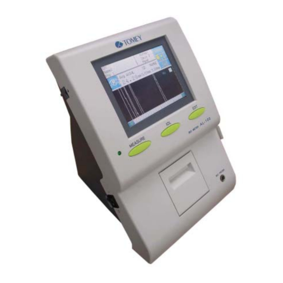
Outline of operation The AL-100 is an ultrasound instrument designed for measuring the axial length of the eye for medical ophthalmic use. Acoustic output is switched off after measurement. Ultrasound energy is emitted from the probe tip. The probe acts as both the transmitter and receiver of ultrasound en- ergy. - Page 14 This page is intentionally blank.
-
Page 15: Names And Functions Of The Components
2 NAMES AND FUNCTIONS OF THE COM- PONENTS Front and right side of AL-100 and biometry probe... - Page 16 (1) Display (touch panel) Measurement data and other information are displayed on the screen. The instrument is operated by touching the keys. (2) Probe holder When the probe is not in use, place them in the holder. (3) Terminal of Biometry Probe The Biometry probe is connected here.
-
Page 17: Back And Left Side Of Al-100
Back and left side of AL-100... - Page 18 (1) Communication Cable Terminal The communication cable is connected here. (2) Power supply terminal The power cord is connected here. (3) Fuse holders Fuses are in use in these holders. (4) Power switch Press the “ I ” side of the switch to turn on the power. Press the “ O ” side to turn it off. (5) Contrast adjuster Controls the contrast of the screen (6) Power cord with 3-prong plug...
-
Page 19: Operation Procedures
3 OPERATION PROCEDURES Safety precautions ALWAYS cleans the probe tip before taking a measurement on a human eye. NEVER use the probe if there is any visible damage to its tip. Such use may cause an incorrect maeasurement and/or damage to the cornea. This instrument is designed exclusively for ophthalmic use. -
Page 20: Preparation Before Use
Connecting the power cord Power cord should be plugged into the terminal with a proper direction. Plug the power cord connector (1) into the terminal (2) on the back of the AL-100. All of 3-Pin in the plug must be connected. -
Page 21: C) Connecting The Foot Switch
Plug the connector (1) for the foot switch to the terminal (2) labeled FOOT SW on the back of the AL-100. Line up the slot of the connector with the tab on the terminal. To source the connector, turn the locking ring (3) until you hear it click into place. -
Page 22: Connecting The Option Parts
3.2.2 Connecting the option parts a) Inserting and removing the memory card Before using memory card for the first time, set the bat- tery in accordance with the instruction Manual for Memory Card (located in the box that contains the catd). Follow the instructions for BN-HSR series. -
Page 23: B) Chin Rest Installation (Al-1100)
b) Chin rest installation (AL-1100) An optional chin rest with a fixation light is available for use when measuring axial length. “Installing the chin rest” (Figure 1) (Figure 2) Make sure that the slider moves. From the operator’s side, carefully insert the biometry probe into the slider until it locks into place. - Page 24 “Connecting the fixation lamp power plug” Insert the power plug (1) for the chinrest fixation lamp into the terminal (2) labeled “FIX LIGHT” on the back of the AL- 100.
-
Page 25: Measurement Procedures
Measurement procedures 3.3.1 Biometry mode setup a) Turning the power on and initial adjustments ALWAYS clean the probe tip before taking a measurement on a human eye. NEVER use the probe if there is any visible damage to its tip. Such use may cause an incorrect measurement and/or damage to the cornea. -
Page 26: B) Start Up Screen
Tilt the screen forward by pulling out the “legs” (3) on the bottom of the instrument, if desired. b) Start up screen The probe is automatically calibrated, when the screen is shown. The catalog screen (Ready to measure screen) is shown, when the calibration is completed without any problem. - Page 27 (2). Press OK to go to the catalog screen. The measurement cannot be done even on the catalog screen, if “Probe error!” is displayed. See Troubleshooting if “Probe error!” shows many times. Contact your TOMEY Representative, if the problem remains.
-
Page 28: Front Button
3.3.2 Front button 1) MEASURE The catalog screen (Ready to measure) screen is shown, when pushing this button. The settings with Index data input, selecting the eye to be measured, Contact/Immer- sion and selection of Measurement methods are also done with this button. 2) IOL The IOL calculation screen appears, when pushing this button. -
Page 29: Measurement
3.3.3 Measurement Press MEASURE button to go into measurement mode. a)Data review window / Measurement window Data Review Window Window will be switched from Data re- view to measurement automatically, when it is taking data. Measurement Window 3-11... -
Page 30: Settings Of The Measurement Conditions
3.3.4 Setting of the measurement conditions Press “New” key and delete data of both eyes, before tak- ing new patient. Otherwise two patients’f data may be mixed up and cause serious probelm. a) Deleting data measured for both eyes (Measuring preparation for new patient) Press the button (1) to measure new patient. -
Page 31: B) Setting The Eye To Be Measured
b) Setting the eye to be measured Touch Eye key to select the eye you wish to measure (right or left). Axial length data and IOL power calculation result of each eye are acquired with different data storage. Please make sure the display is showing right eye, when measuring right eye, and left eye for left. - Page 32 (Figure2) Touch the Index key (1) on the measurement window (Fig.1 )to display the Name/ID entry window. (fig.2) Touch the number keys and the alphabetic character keys (2) to enter the patient name, ID number and physician’s name. If the physician’s name is already registered in the physician list, it can be selected by pressing the corresponding number.
-
Page 33: D) Physician's List Entry
d) Physician’s list entry Physician’s name can be stored in advance as a list. (Figure1) Touch Entry key to reverse the color of “Entry” icon. [Figure1] Touch PhyList, which you wish to change and it reverses the color. Type the name with the alphabetic character keys. Touch the “Enter”... -
Page 34: E) Setting Items For Measurement
e) Setting items for measurement e-1) Select OD/OS, Eye type, gain, Hand/Manual/Chin and Contact/Immersion can be selected. (Figure 1) Touch Eye type/ Gain key(1) to go into its setting window. “Figure2” (Figure 2) Select the Key (2) for measured eye which suits the eye to be measured. - Page 35 (Figure 3) When (3) is again selected, the highlighted display is released and the screen is returned to that in (Fig. 2). Select the (6) key, the Mean Velocity (7) or Sectional Velocity (8) is selected. If the EXIT key (4) is selected, the screen will be returned to that shown in (Fig.
- Page 36 [Setting the eye type and converted velocity] The AL-100 can be set to measure the following tyoes of eyes: Normal Select when the lens nucleus of the patient’s eye is rather soft, e.g., incipient cataract. Average velocity Average axial length velocity (Avg) : 1500 ~ 1600 m/s...
- Page 37 [ACD] and [LENS] are not displayed with Aphakic, and [LENS] is not displayed with Pseudophakic. Posterier lens waveform might not be recognized, due to mul- tiple echo with Dense Cataract mode. Measured data is displayed. Measured data may not be displayed. Measured data is not displayed.
- Page 38 e-3) Setting of the Contact / Immersion Contact / Immersion mode can be changed with touching “Contact” or “Immersion”. (Figure 1) Select Contact with contact mode and Immersion with immersion mode. Selected key should be highlighted. [How to apply biometry probe for Contact mode] The tip of the probe should be applied to the center of the cornea verticaly.
- Page 39 [Measurement of axial length with immersion mode] Measurement without using immersion attachment (cap) Top of the biometry probe can be immersed in the water. In case of using corneal protective gel, care must be taken not to put excessive amount of the agent, which may otherwise influence measurement data.
- Page 40 Setting of the measurement mode The Hand, chin measurement (automatic measurement) or the manual measurement can be selected. (Figure 1) Push 1,2 or 3 to select the measurement mode. Select key is shown as reverse highlighted. 3-22...
-
Page 41: Actual Measurement
It cannot be used for determining the precision of the instrument or for calibration of the instrment. Check the performance of the AL-100 by using the biometry test piece(found in the box containing the biometry probe). Select the following settings:... -
Page 42: C) Measurement
c) Measurement There are two automatic modes, hand-held and chin rest, and one manual mode. Hand (Hand-held) (Figure 1) Touch “New” key(1) to measure new patient’s eye. Apply biometery probe perpendicular to the cornea. The measurement window will be automatically shown, when certain waveform conditions are satisfied. - Page 43 (Figure 2) When a satisfactory measurement is taken, the instrument makes a “beep” sound. The instrument acquires the data automatically, when the data becomes stable. The instrument makes a “beep” sound, when a data is acquired. The instrument shows the waveform, average axial length and maximum(as L) / minimum(as S) measurement data.
- Page 44 Chin (Chin measurement) Select “Chin” for taking measurement using the Chin Rest. The operation and display of the Measure, Setting screen and the Measure screen are same as those done for Hand (hand measurement). (See Figs. 1 and 2.) 1) Measurement is performed by using the Chin Rest. 2) Assemble the Biometry Probe in accordance with “3.3.1 c) Assembling of the Biometry Probe”.
-
Page 45: D) Retake
d) Retake To delete all data currently displayed for either the right or the left eye, press the Retake key (1) until you hear a beep. Note: This deletes currently acquired data from the instrument memory; it does not delete data stored on the memory card. -
Page 46: Acceptable Waveforms
(Figure 2) The waveform to the right of this cursor(2) is taken as the retinal.(Fig2) 3.3.6 Acceptable waveforms a) Contact mode In the automatic measurement modes, waveforms are evaluated and acquired only if the following criteria are met: 1) The following crests rise above the level cursor: Normal: The spikes of the back and front of the lens and of the retina. -
Page 47: B) Immersin Mode
The following items are used for checking to see if ultra- sound can correctly catch the axial length and, therefore, reasonable waveforms are obtainable, provided that these items are not good conditions for taking-in of measurement data. The retinal echoes rise high.: implies that the probe is applied perpendicular to the cornea. -
Page 48: Edit
3.3.7 EDIT Press EDIT button on the front, and show EDIT window. 3-30... -
Page 49: A) Edit Screen
a) EDIT Screen The waveforms for each eye of the current patient mea- surements can be retrieved and reviewed at any time dur- ing the measuring process. “Displayng a waveform” (Figure 1) The waveform will be shown as shrunk wave on “2”. Press up and down cursor keys to switch to the waveform, you desire. - Page 50 [Deleting individual measurements] (Figure1) Touch the up and down arrow keys (1) to move to the measurement you wish to delete. Touch “Delete” key (2) to delete the data. “Delete” key will change into “Recall” after delete and press the “Recall”...
-
Page 51: Caliper Function
3.3.8 Caliper function The value that is measured, and displayed by the caliper function might be different from the result of a measure- ment because of the rough estimate value. Measurements by the caliper function are the reference values and it is not reflected in the IOL calculation. It is a function to operate the location of measurement of the cornea, the front side of LENS, the rear side of LENS, and the retina, and to measure the distance between each... - Page 52 (Figure 1) It switches to the caliper screen pushing Calip key (1) (Calip key to the Echo screen). (Figure 2) The green, active caliper line is moved pushing caliper line movement key (2). It is displayed in the distance (Distance the under) after it moves. The active caliper line changes if Fix key (3) is pushed.
-
Page 53: Iol Calculation
IOL calculation 3.4.1 IOL power calculation Press “IOL” button to show IOL calculation window. 3-35... -
Page 54: Calculation
3.4.2 Calculation The calculation result with the UD-6000 might be dif- ferent from that with the AL-100, due to the difference of internal valid numbers. When imaginary number is created, the calculation re- sult will be displayed as an “ERROR”. -
Page 55: B) Data Entry For Iol Calculation
(Figure 2) Select the formula by touching the number on the left side (2) of desired formula. Selected formula is shown as highlighted. Only one formula can be selected with AL- 100. Touch “Exit” key (3) to go back to IOL calculation (Fig.1). - Page 56 Prepare to enter axial length / ACD by touching the Axial key (2) / ACD key (1). The databox will be reverse highlighted. Touch the number keys (3) to enter the axial length value.(ACD key is shown only when it is used by a formula) [Acceptable range] AXIAL...
-
Page 57: C) Constants (Aconst, Sf, Acd)
[D-Ref] Desired postoperative refraction (Figure 3) Prepare to enter the desired postoperative refraction by touching the D-Ref key(1). The databox will be reverse highlighted. Touch the number keys (2) to enter the data. The acceptable range is -30.0 ~ + 10.0 D. Complete the data entry by touching D-Ref key(1). - Page 58 Select the Lens Constant key (1) in the screen of (Fig. 1), so the key will be highlighted to display the screen of (Fig. 2). (Figure 2) Enter the lens constant with the Number Enter key (2) in the screen (Fig. 2). If the IOL registration has been made, enter the data from the lens data (3) displayed in the screen (Fig.
-
Page 59: D) Iol Power Entry
d) IOL power entry IOL Data can be stored up to 10 lenses. (Figure 1) Touch the “Entry” key (1) to show IOL Entry Window(Fig2). (Figure 2) Touch up and down cursor(3) to select the position to enter data. Enter Company name(Company), Model No(Model No), A constant (Aconst) and Lens constants (Aconst, SF, ACD-Const, a0, a1 and a2). -
Page 60: E) P/C Value (Personal Corresponding Value)
e) P/C value (Personal Corresponding Value) After the IOL has been implanted and the postoperative refraction has been determined, the lens constants (per- sonal A-const, and corresponding value) can be calculated as follows. (Figure 1) Touch P/C Val key(1) on IOL calculation(Fig 1) to display the P/C value calculation screen(Fig 2). - Page 61 (Figure 3) The selected databox will be reverse highlighted.(Fig 3) <AXIAL> Axial length <ACD> Anterier Chamber Depth <K1 / K2> Corneal Refractive Power / Corneal Raduis <Post Ref> Postoperative refractive power [Acceptable range] -30.0 ~ +10.0D <Imp. dpt> Refractive power of implanted IOL [Acceptable range] -10.0 ~ +80.0D <Aconst>...
-
Page 62: F) Assistant Function
f) Assistant function Imp-IOL Entry Enter the implanted IOL model name. This model name is saved in the internal memory or the Memory card. Press the IOL front button provided in the front of the Main Unit to display the IOL Calculation screen (Fig. (Figure 1) Touch the Imp-IOL key (1) in the screen (Fig. -
Page 63: Printout
Printout 3.5.1 Printout procedure After biometry measurement, IOL calculation or pachymetry measurement, touch the Print key(1) to initiate printing. a) Data review window b) Echo window c) IOL calculation window d) P/C Val window 3-45... - Page 64 e) EDIT window Average data will be printed, when touch print key with- out specifyng data by select key(2) on EDIT Window. (Figure 1) f) Communication screen after transmitting data The screen(1) will be shown after transmitting data. See [3.6.6 b)] (Figure 1) 3-46...
-
Page 65: Sample Printout
3.5.2 Sample printout a) Sample biometry printout Standard mode (with Extended Export) (1) Time/Date (2) Model name; version (3) Clinic ID/NAME (4) Clinic Address (5) Physician’s name (6) Patient ID number (7) Patient name (8) Patient’s sex (9) Eye (Right/Left) (10) Measurement mode (11) Mean velocity / Sectional velocity (12) Eye type... - Page 66 Standard mode (without Extended Export) (1) Time/Date (2) Model name; version (3) Name of physician (4) ID number (5) Name of patient (6) Sex of patient (7) Eye to be measured (8) Measurement mode (9) Mean velocity / Sectional velocity (10) Eye type (11) Contact / Immersion (12) Average axial length velocity...
- Page 67 Simple mode (1) ID number (2) Eye to be measured (3) Measurement mode (4) Mean velocity / Sectional velocity (5) Eye type (6) Contact / Immersion (7) Average axial length velocity (8) Lens velocity (9) ACD velocity (10) Gain (11) Average axial length (12) Standard deviation of axial length data (13) Difference between minimum and maximum axial length...
-
Page 68: B) Sample Iol Power Calculation Printout Following Biomtery (Spk/T)
b) Sample IOL power calculation printout following biometry (SRK/T) Standard mode (with Extended Export) (1) Time/Date (2) Model name; version (3) Clinic ID/NAME (4) Clinic Address (5) Physician’s name (6) Patient ID number (7) Patient name (8) Patient’s sex (9) Eye (Right/Left) (10) Axial length (11) ACD (12) Corneal refractive power or Corneal Radius... - Page 69 Standard mode (without Extended Export) (1) Time/Date (2) Model name; version (3) Physician’s name (4) Patient ID number (5) Patient name (6) Patient’s sex (7) Eye (Right/Left) (8) Axial length (9) ACD (10) Corneal refractive power or Corneal Radius (11) Desired postoperative refraction (12) IOL calculation formula (13) Lens A/Lens B (14) Lens constants...
- Page 70 Simple mode (1) Time/Date (2) Model name; version (3) Physician’s name (4) Patient ID number (5) Patient name (6) Patient’s sex (7) Eye (Right/Left) (8) Axial length (9) ACD (10) Corneal refractive power or Corneal Radius (11) Desired postoperative refraction (12) IOL calculation formula (13) Lens A/Lens B (14) Lens constants...
-
Page 71: C) Sample Printout Using P/C (Personal Corresponding) Surgeon Factor Value
c) Sample printout using P/C(Personal Corresponding) surgeon factor values Standard mode (1) Time/Date (2) Model name; version (3) Physician’s name (4) Patient ID number (5) Patient name (6) Patient’s sex (7) Eye (Right/Left) (8) Axial length (9) Anterier chamber depth (ACD) (10) Keratometry values (11) Postoperative refraction (12) Implanted IOL power... -
Page 72: D) Sample Data Communication Printout
d) Sample data communication printout (1) Time/Date (2) Model name; version (3) Physician’s name (4) Patient ID number (5) Patient name (6) Patient’s sex (7) Eye (Right/Left) (8) Eye type (9) Average axial length velocity (10) Lens velocity (11) ACD velocity (12) Average axial length (13) ACD (14) Lens thickness... -
Page 73: Data Save / Load / Delete
Data save / load / delete Data saving, loading and deleting will be done on IOL calculation and EDIT screens. 3.6.1 Data save Measurement data and calculation result can be stored on the internal memory or Memory card. Patient ID number will be required to save data. The memory card must be formatted before its initial use. - Page 74 Touch Save key (1) to show dialog window to select “Internal” or “Card”. (Figure 2) “Save data on internal memory” Touch Internal key (2) The saving will be completed, when you hear short beep and the display return to the EDIT window. Less than 6 data can be stored with the internal memory.
-
Page 75: B) Data Save On The Iol Calculation Window
b) Data save on the IOL calculation window Select the IOL front button to display the IOL Calculation Window. (Figure 1) Select the Save key (1) in the screen of (Fig. 1), to display the screen of (Fig. 2). Then, select “Internal” or “Card”... -
Page 76: Data Loading
“Save data on internal memory” Touch Internal key (2) The saving will be completed, when you hear short beep and the display return to the IOL window. Less than 6 data can be stored with the internal memory. (The number, which can be stored onto the internal memory varies, depending on the size of the data) * Biometry data, on the internal memory, will NOT be automatically deleted with this process. - Page 77 (Figure 2) “Loading from the internal memory” Touch Internal key (2). (Fig 2) Desired data can be selected with up and down cursor (5) on Loading window (Fig 3). Touch Select key (6) to select the data. The color of INDEX will be changed into “green” after loading.
- Page 78 “To cancel data loading” Touch Cancel key (4) to make short beep and cancel. Figure 3 Figure 4 Figure 5 3-60...
-
Page 79: Sort
3.6.3 Sort Saved data can be sorted as desired. Press EDIT button to show EDIT window. (Fig 1) (Figure 1) Touch Load key (1) to show the display on Figure 1. (Figure 2) Touch Card key (4) to show LOAD DATA display (Fig Touch Sort key (6) on the display (Fig 3) to show Sort Condition screen.(Fig 4) 3-61... - Page 80 (Figure 3) (Figure 4) 3-62...
-
Page 81: Deleting
3.6.4 Deleting Only data, saved by AL-100, can be deleted. Once the data is deleted, it will not be restored. Please pay special attention not to delete important data. Touch the Load key on EDIT window, to go to LOAD Window(the internal memory or the Memory card) in which the memory to be deleted is preserved.(Fig1) -
Page 82: Momery Card Format
3.6.5 Memory card format The memory card can be formatted with AL-100. The memory card must contain battery inside. Read the operation manual of the battery and follow the instruc- tion. The memory card must be formatted before its initial use. -
Page 83: Data Communication
IEC601-1 system standard. If indoubt, contact the Tomey technical service department, or your local Tomey representative. Connect the communication cable (3) to the adapter and secure the connection by tightening the screws. - Page 84 “Pin positions of the RS-232C connection terminals” 9 pins D-sub Pin # Signal Note: Pin# 4 and 6 are connected inside the instrument. So as pin# 7 and 8. 3-66...
-
Page 85: B) Sending Data
b) Sending data The Instrument is capable of sending data from the IOL Calculation screen and the EDIT screen to any external communication equipment. “IOL calculation screen” “EDIT screen” 1) Select the IOL front button to 1) Select the EDIT front button to display the IOL Calculation screen. - Page 86 (Figure 3) Check the displayed data and select the OK key (3) to send the data. Next select the down key(4) to display the data of axial length. If you want to cancel sending data, select the Cancel key (5). When sending data is completed, the screen of (Fig.
-
Page 87: C) Receiving Data
c) Receiving data Since data receiving cannot be made if there is any data left in the screen, display the Measure, Wait screen of (Fig. 1) and select the New key (1). (Figure 1) For changing the screen for data communications, display the IOL Calculation screen or the EDIT screen and select the COM key (2). - Page 88 (Figure 3) Select the Receive key (3) in the screen of (Fig. 3) to display the Data Receiving screen of (Fig. 4). (Figure 4) When the personal computer is ready for sending data to the Instrument, select the OK key (4) to start receiving data by Instrument.
-
Page 89: Utilities
Utilities Press EDIT button to show EDIT window. (Figure 1) Touch Utility key(1) to show Utility window.(Fig 1) 3.7.1 Contents of utilities Exit Time and Date Return to EDIT window. Enter current date and time. Print Mode Select print mode. Extended Export Sound Set Opens the Extended... -
Page 90: Biometry/Iol Power Calculation Utilities
3.7.2 Biometry/IOL power calculation utilities a) Time and Date To set the date and time: (Figure 1) Touch the Time and Date key (1) on the biometry Utility screen(Fig 1) to display Time and Date screen (Fig 2). (Figure 2) Touch each item key (2) to prepare to enter information for that item. -
Page 91: B) Sound Setup
b) Sound setup To adjust the sound: (Figure 1) Touch Sound Set key (1) on the biometry Utility screen (Fig 1) to display the Sound Adjustment window (Fig 2) 3-73... -
Page 92: C) Print Mode Setup
c) Print mode setup To set the printout options. (Figure 1) Touch Print Mode Key (1) to display Print Mode screen(Fig 2). Standard: Standard Printing Contents Simple: Simple Printing Contents (Figure 2) Two Print modes can be set for Measurement (2) and IOL (3). -
Page 93: D) Fix Light On/Off
d) Fix Light ON/OFF To turn ON/OFF the fixation light on biometry probe. Touch FIX LIGHT Key (1) to turn it ON/OFF (Fig 1). 3-75... -
Page 94: E) Extended Export Setting (Extended Export)
e) Extended Export setting (Extended Export) Set whether to output the information related to the clinic and measurement techniques. Press the Extended Export key (1) to open the Extended Export setting screen (Fig. 2). (Figure 1) When the Enable key (2) is activated, the following information is output when printing or sending the data. -
Page 95: Memory Card (Option)
If data on the memory card are edited using a computer, the card no longer can be used with the AL-100. It will be necessary to reformat the card. The PC memory card used with the AL-100 is an SRAM type card. -
Page 96: Memory Card Battery
Battery life The Memory Card consume its battery even when the memory card is not used with AL-100. The life of the bat- tery varies as a function of the memory capacity, as indi- cated below. -
Page 97: Reading The Memory Card On Windows Pc
3.8.3 Reading the memory card on Windows PC a) Rewriting the Windows PC system configuration file ® <Windows 95/98> ® “Windows 98 Second Edition” loading is to be performed from 1), while for other than that, loading is to be from Open the PC card “PC”... - Page 98 <Windows Me> ® There are some cases that, even if this method is given, the information saved in the Memory Card cannot be read. In such a case, consult the Manufacturer or your local repre- sentative. Open the Explorer to move such information files to the Drivers\Storage\Flash folder of Windows* Me CD-ROM.
- Page 99 Click the [Next] button (1) and proceed in the window of (Fig. 4). Select [Display known driver of this device and select its list.], next click the [Next] button (3), and proceed in the next Window of (Fig. 5). Select “Memory technology driver” (4) and click the [Next] button (5), to proceed in the next Window of (Fig.
-
Page 100: Taking Out The Memory Card From Pc
3.8.4 Taking out the memory card from PC Windows 95/98/Me ® Figs show the cases of Windows ® Take out the Memory Card from the personal com puter in the following procedures, which may other wise cause the personal computer to malfunction. Click the [Start] button(1), next point the [Setting], and then click (2), so the control panel will be displayed. - Page 101 <Windows 2000> ® Display the control panel in the same manner as <In (Figure 1) case of Windows 95/98> and next double-click the <Add and Delete Hardware>(Fig. 1), so the starting window for “Add and Delete Hardware Wizard” will be displayed. (Fig. 2) Click the [Next] button (1), so the window for (Figure 2) selecting the operation related to hardware will be...
-
Page 102: Shut Down
Shut down Please shut down the main power, when the unit is not used. Please do not shut down, while the unit is in the following situation: 1, Loading / Saving data onto either Memory Card (Option) or internal memory. 2, The unit is receiving / sending data between external devices. -
Page 103: Technical Reference
4 TECHNICAL REFERENCE 4.1 IOL calculation formulae 4.1.1 SRK II a. Emmetropic IOL power (D) = A1 - 0.9K - 2.5L emme b. Ametropic IOL power (D) - REF CR ament emme c. Desired postoperative refraction (D) = (P - P) / CR emme Where: L <... - Page 104 d. Personal A-constant A = P + AREF RF + 2.5L + 0.9K - COR Where: Power of IOL implant (D) AREF: Postoperative refraction <equivalent to the spherical index (D) = S + C/2 Cylindrical index (D) Spherical index (D) Refractive factor if P >16, then RF = 1.25 if P...
-
Page 105: Srk/T
4.1.2 SRK/T a. Emmetropic IOL power (D) 1000na X emmme (L1 - C1) Y b. Ametropic IOL power (D) 1000na {X - 0.001REF (V X + L1 r)} ame t (L1 - C1) {Y - 0.001REF (V Y + C1 r)} c. -
Page 106: Holladay
4.1.3 Holladay a. IOL power (D) 1000na {X - 0.001REF (V X + L2 r) (L2 - C2 - SF) [Y - 0.001REF {V Y+ r (C2 + SF) b. Desired postoperative refraction (D) 1000na X - P Q Y emme na (V X + L2 r) - 0.001P Q {V Y + r (C2 + SF)} Where:... - Page 107 c. Personal SF SF = { -BQ - - 4AQ CQ} / (2AQ) - C2 Where: AQ = (nc - 0.001AREF {V (nc - 1) - r} BQ = 0.001AREF {L2 V (nc - 1) - r ( L2 - V na)} - {L2(nc - 1) + na r} CQ1 = 0.001AREF [V {na r - L2 (nc - 1)} + L2 r] CQ2 = 1000na {na r - L2 (nc - 1) - CQ1} / P...
-
Page 108: Haigis Standard / Haigis Optimized
4.1.4 Haigis standard / Haigis optimized a. IOL power (D) 1000na L - d 1000 Where: z = DC + REF V 1000 d = a0 + a1 ACD + a2 L (ACD = 0) d = (a0 - 0.241 a1) + (a2 + 0.139 a1)L (ACD = 0) a0 = 0.62467A - 72.434 ..... - Page 109 c. Personal A-constant d - a1 ACD - a2 L + 72.434 (ACD = 0) 0.62467 d - L(a2 + 0.139 a1) + 0.241 a1 + 72.434 0.62467 (ACD = 0) Where: P (L*z+1000na) - P (L z + 1000na) - 4P z (1000L na z + 1000L na P - 1000 2P*z AREF...
-
Page 110: Showa (Modified Srk Formula For Japanese)
4.1.5 Showa (Modified SRK formula for Japanese) a. Emmetropic IOL power (D) < L < L < b. Desired postoperative refraction by spectacle (D) < L < L < c. Personal A-Constant < L < L < Axial length (mm) Average refractive power (D) = (K1 + K2) / 2 REF: Desired postoperative refractive power (D) A - constant... -
Page 111: Hoffer Q
4.1.6 Hoffer Q a. Emmetropic IOL power (D) 1336 1.336 L - C - 0.05 1.336 C + 0.05 K + R 1000 Where: 1 - 0.012 Rx b. Desired postoperative refraction by spectacle (D) Rx = 1 - 0.012 Ri Where: 1.336 1.336... -
Page 112: Shammas-Pl
4.1.7 Shammas-PL This formula is for POST LASIK. a. Implanted IOL power (D) for emmentropization 1336 emme L - 0.1(L - 23) - (C + 0.05) 1.0125 C + 0.05 1336 b. Implanted IOL power (D) for ametropia 1336 amet L - 0.1(L - 23) - (C + 0.05) 1.0125 C + 0.05... - Page 113 d. Personal A-Constant 1336 . a 1336 . a 1336 - 0.05 + 64.4 Lc a + 0.5835 1336 1336 1.0125 Kc + AREFc AREFc:Refractive power of the eye at corneal refractive surface 1000 1000 - VD AREF AREF: Eye refractive power after surgery (D) 4-11...
-
Page 114: 4.2 Axial Length Calculation With Biometry
4.2 Axial length calculation with biometry 4.2.1 Normal Axial length is calculated using the following formula: Where: Axial length Average ultrasound velocity Time 4.2.2 Dense Cataract Axial length is calculated using the same formula as for the normal lens. 4.2.3 Aphakic Axial length is calculated using the same formula as for the normal lens. -
Page 115: 4.3 Version Information
4.3 Version information (Figure 1) Start up screen will be shown after turning on the unit. The software version (1) is displayed to confirm. 4-13... -
Page 116: 4.4 Acoustic Output
4.4 Acoustic output 4.4.1 MI (MECHANICAL INDEX) MI is a parameter to show mechanical bio-effects of ultra- sound. Examples of mechanical effects are motion (or streaming) around compressible gas bubbles as ultrasound pressure waves pass through tissues, and energy released in the collapse, via cavitation, of transient gas bubbles. -
Page 117: Inspection And Maintenance
This warranty also shall NOT apply if the product has not been installed, operated or main- tained in accordance with the INSTRUCTION MANUAL of Tomey Corporation (here in after called "Tomey"). Neither seller not Tomey shall be liable for any damages caused by purchaser's failure to follow instruction for proper installation, use and maintenance of product. -
Page 118: Fuses
Fuses Unplug the power cord when replacing 1) Turn the AL-100 off and unplug the power cord from the power outlet. 2) Rotate the fuse holders counter clockwise approximately 90 degrees using a coin or a screwdriver, and the holders will pop out. -
Page 119: Routine Maintenance
Routine maintenance 5.3.1 Maintenance of the probe When disconnecting the probes, be sure to hold the plug, not the cable, otherwise the cable will be damaged. Make sure that there are no crack, chip and chap of the eye contacting part of the probe, no looseness of the con- nector, no damage of the cable. -
Page 120: Cleaning And Disinfection Of Measurement Probes (For Europe)
5.3.2 Cleaning and Disinfection of measurement probes (for Europe) [Specific Section for European continent] Following the legal requirements and regulation in the country. Refer to the instruction manual of concerned test-fluid for detail. a) Cleaning Holding and pulling the cord may damage the inner core wires. - Page 121 Biometer PERFEKTAN TB (4% solution) ® One clinical tested cleaning product would be: PERFEKTAN ® (4% concentrations and an exposure times of 30 min) Antimicrobial Properties Perfektan TB is: ® b a c t e r i c i d a l ( i n c l . M R S A = m u l t i r e s i s t a n t Staphylococcus aureus) tuberculocidal fungicidal (C.
-
Page 122: Maintenance Of The Main Unit
5.3.3 Maintenance of the main unit Do not use organic solvents for cleaning the AL-100 as they may cause damage to the surface. When removing the power cord, grasp the plug, not the cord and do not apply undue force. -
Page 123: Printer Paper
Printer paper Replace the paper when red lines appear on both sides of the paper. When opening the printer cover, pay special attention to the paper cutter on the cover, not to cut your finger or hand. 1) Open printer cover (1). 2) Remove the used roll of paper. -
Page 124: Storage
Storage Do not store this instrument in a location where it might be exposed to water or chemicals. Avoid excessive atmospheric pressure, high temparature, excessive humidity, poor ventilation, direct sunlight, dust, salt or sulfer in the air. Do not store this instrument near chemical substances or in a location where gas may be generated. -
Page 125: Packing Materials
Packing materials Keep the carton and packing materials for future use. If you discard the packing materials, be sure to comply with local ordinances and regulations for disposal. This instrument contains the board with lithium-ion bat- tery inside the body. If you discard the instrument, be sure to complay with local ordinances or regulations for disposal. - Page 126 This page is intentionally blank. 5-10...
-
Page 127: Troubleshooting
6 TROUBLESHOOTING Before self-judging a trouble as a malfunction or failure, check the following items. If you cannot solve your trouble or problem by the following countermeasures, consult your local representative. Do not remove the enclosure of this Instrument, or you may otherwise be exposed with high voltage. - Page 128 Nothing is displayed in the monitor screen. The Auto Power Off Function (which auto- Cause1 matically turns the screen off if no opera- tion is given for 15 minutes) is in operation. Touch the monitor screen. Solution The switch for maintenance provided on Cause 2 the rear side is off the center position.
- Page 129 tion of the touch panel is shifted many times while in operation, consult your lo- cal representative. The time display is not working The loading data is being displayed. Cause1 While any loading data is being displayed, Solution the date “and time of its measurement made is displayed.
- Page 130 In process of setting the Immersion Solution mode, use the Immersion attachment by means of the procedures specified in "3.6.5 a) Using of the Biometry Probe in the Contact Mode/Immersion Mode" or give measurement by placing super sounds. When directly applying the Probe to the cornea, select the Contact mode.
- Page 131 Set for Manual measurement. (See Solution "3.6.3 e) Setting of Measurement Method.") Measurement data are not stable or proper. The Probe is not connected correctly. Cause1 Connect the Probe correctly until it is se- Solution curely locked, by specified procedures mentioned in "3.2.1 b) Connecting of the Biometry Probe".) The cornea is applied with an undue pres-...
- Page 132 give the settings of the Immersion Mode and the Contact Mode and take measure- ments in the procedures prescribed in “3.3.4 e-3”. Handling of the Biometry Probe in the Contact Mode and the Im- mersion Mode." Measurement is given by directly applying Cause 7 the Probe to the cornea, without using super sounds in the Immersion Mode.
- Page 133 The monitor sounds for Biometry does not stop, or mea- surement values are taken at the time when measure- ment is not being taken. The tip of the Biometry Probe is wetted Cause1 with water. Remove the water from the tip of the Solution Probe.
- Page 134 Fixation Light is not ON. It might be turned OFF from Fix Light set- Cause1 ting in Utilities. Go to Utilities, and press “Fix Light” to Solution turn it ON again.(See 3.7.2d) <Data saving> Data cannot be saved in the internal memory. An ID number has not been inputted for Cause1 data to be saved.
- Page 135 The Memory Card has no sufficient space. Cause 4 ("Memory Full!!" is displayed.) Replace the Memory Card in trouble Solution with the new Memory Card, or delete un- necessary data before saving. Deleting of data must be done with this Instru- ment.
- Page 136 puter, a) Rewriting of Config. Sys file of Windows personal computer provided with the PC card slot. No device driver of the Memory Card ex- Cause 3 ists. If the personal computer provided with Solution the Memory Card slot is installed with the Windows, "CSMAPPER.
-
Page 137: Spare Parts And Option Parts
7 SPARE PARTS AND OPTION PARTS The following spare parts and option parts are available from your local representative or distributor of Tomey Corporation. Option parts Memory Cards (512Kbyte, 1Mbyte, 2Mbyte) Specify a “Memory Card for AL-100”. Chin Rest AL-1100... -
Page 138: Spare Parts
Spare parts Printer paper roll for built-in Printer Specify a “Printer Paper Roll for Built-in Printer for AL-100”. Immersion attachment Specify “Immersion Attachment for AL-100”. -
Page 139: Specifications
8 SPECIFICATIONS Specifications 8.1.1 Biometry / IOL calculation Measurement range Axial length: 15 - 40 mm Inspection results Anterior chamber depth : 1.8 - 7mm Lens thickness: 2 - 6mm Instrument accuracy Measuring accuracy: ± 0.1mm Measurement resolution: 0.01mm Converted sound velocity set when shipped Normal Average axial length sound velocity: 1,550m/s Crystalline lens sound velocity:... -
Page 140: Main Unit
IOL calculations SRK ll formula SRK/T formula HOLLADAY formula HAIGIS standard formula HAIGIS optimized formula Showa (Modified SRK formula for Japanese) Hoffer Q formula Shammas-PL formula Biometry Probe Type: Solid type Fixation lamp: Built in the Probe (red LED) Oscillator frequency: 10MHz 5.3mm φ... -
Page 141: Energy And Other Consumptions
Energy and other consumptions 8.2.1 Influences of ultrasound energy to human body Since this Instrument is exclusively designed for ophthalmic applications only, do not use it for any purposes other than for its designed purpose. This Instrument is designed as the super sound diagnosis equipment specialized for ophthalmic applications. - Page 142 MI : the Mechanical index Ispta3 : the derated spatial-peak temporal-average intensity. Isppa3 : the derated spatial-peak pulse-average intensity. pr.3 : the deratad peak rarefactional pressure. Wo : the ultrasonic power fc : the center frequency Zsp : the axial distance at which the reported parameter is measured.
- Page 143 ACOUSTIC ATTENUATiON COEFFICIENT Aaprt : -12dB OUTPUT BEAM AREA Deq : EQUlVALENT APERTURE DIAMETER deq : EQUIVALENT BEAM DIAMETER fawf : ACOUSTIC WORKING FREQUENCY Ipa : PULSE-AVERAGE INTENSITY Ipa, a : ATTENUATED PULSE-AVERAGE INTENSITY Ipi : PULSE-1NTENSTY INTEGRAL Ipi, a : ATTENUATED PULSE-INTENSTY INTEGRAL MI : MECHANICAL INDEX...
-
Page 144: 8.3 Noise
8.3 Noise This instrument makes mechanical noises at the following operations. When starting printout When touching the key buttons When taking measurements (such as when taking measured data) 8.4 Environment conditions Use this unit under the environment conditions as followings. Place : Indoor without sunshine Temperature :... -
Page 145: 8.5 Declaration Of Conformity To Emc
Table 201 The AL-100 is intended for use in the electromagnetic environment specified below. The customer or the user of the AL-100 should assure that it is used in such an environment. Emissions test Compliance Electromagnetic environment - guidance... - Page 146 Table 202 The AL-100 is intended for use in the electromagnetic environment specified below. The customer or the user of the AL-100 should assure that it is used in such an environment. Immunity test IEC 60601 Compliance level...
- Page 147 Guidance and manufacturer's declaration - electromagnetic immunity Table 204 The AL-100 is intended for use in the electromagnetic environment specified below. The customer or the user of the AL-100 should assure that it is used in such an environment. Immunity test IEC 60601 Compliance...
- Page 148 AL-100 Table 206 The AL-100 is intended for use in an electromagnetic environment in which radiated RF disturbances are controlled. The customer or the user of the AL-100 can help prevent electromagnetic interference by maintaining a minimum distance between portable and mobile RF communications equipment (transmitters) and the AL-100 as recommended below, according to the maximum output power of the communications equipment.
- Page 149 Fax: +81 52-561-4735 EC-Representative Tomey GmbH Am Weichselgarten 19a 91058 Erlangen GERMANY Tel: +49 9131-77710 Fax: +49 9131-777120 AUTHORIZED TOMEY SERVICE CENTERS Headquarters, Pacific Rim Tomey Corporation 2-11-33 Noritakeshinmachi Nishi-ku, Nagoya 451-0051 JAPAN Tel: +81 52-581-5327 Fax: +81 52-561-4735 Europe...
- Page 150 0120...
Need help?
Do you have a question about the AL-100 and is the answer not in the manual?
Questions and answers